JP5131003B2 - Resin film manufacturing apparatus and method - Google Patents
Resin film manufacturing apparatus and method Download PDFInfo
- Publication number
- JP5131003B2 JP5131003B2 JP2008099135A JP2008099135A JP5131003B2 JP 5131003 B2 JP5131003 B2 JP 5131003B2 JP 2008099135 A JP2008099135 A JP 2008099135A JP 2008099135 A JP2008099135 A JP 2008099135A JP 5131003 B2 JP5131003 B2 JP 5131003B2
- Authority
- JP
- Japan
- Prior art keywords
- resin film
- base material
- stretching
- holder
- cooling
- Prior art date
- Legal status (The legal status is an assumption and is not a legal conclusion. Google has not performed a legal analysis and makes no representation as to the accuracy of the status listed.)
- Expired - Fee Related
Links
Images
Landscapes
- Shaping By String And By Release Of Stress In Plastics And The Like (AREA)
Description
本発明は、樹脂フィルムの製造装置に関し、特には、螺旋構造を有する高分子を含む樹脂フィルム母材を延伸させることによって螺旋構造を有する高分子が一方向に配向された樹脂フィルムを製造するための樹脂フィルムの製造装置及び製造方法に関する。 The present invention relates to an apparatus for producing a resin film, and in particular, to produce a resin film in which a polymer having a helical structure is oriented in one direction by stretching a resin film base material containing the polymer having a helical structure. The present invention relates to a resin film manufacturing apparatus and manufacturing method.
従来、例えば特許文献1などにおいて、種々の樹脂フィルムの延伸装置が提案されている。特許文献1では、オーブン内の側部に設けられたプレナムボックス内において、熱風循環用ファンとエア吹き出しノズルとの間に熱風流速均一化用スクリーンを取り付けることで、フィルムへ吹き出す熱風の、フィルムへの吹き出し速度をフィルムの走行方向において均一化させようとしている。
ところで、従来、ポリ乳酸などの螺旋構造を有する高分子を含む母材を延伸して配向させることにより、圧電性を有する樹脂フィルムを作製が可能であることが知られている。ここで、高い圧電性を有する樹脂フィルムを得るためには、高分子の配向度を高めることが重要である。 By the way, it has been conventionally known that a piezoelectric resin film can be produced by stretching and orienting a base material containing a polymer having a helical structure such as polylactic acid. Here, in order to obtain a resin film having high piezoelectricity, it is important to increase the degree of orientation of the polymer.
例えば、特許文献1に開示された延伸装置では、熱風流速均一化用スクリーンによって、延伸時においてフィルムに吹き付けられる熱風の吹き出し速度が均一化されているため、この延伸装置を用いてフィルム母材を延伸させることで、延伸直後における配向度を高くすることが可能となる。しかしながら、特許文献1では、延伸後のフィルムの冷却については特に言及されていない。一般的には、延伸後のフィルムは空冷されるが、空冷では、冷却速度が遅くなり、冷却工程において、一方向に配向した高分子が元の配向状態に戻ろうとする。従って、得られるフィルムの配向度が低くなってしまう。また、部分的に結晶化が進み、光の透過率、機械的強度、圧電性にムラが生じることもある。
For example, in the stretching apparatus disclosed in
また、冷風を延伸後の樹脂フィルム母材に吹き付ける方法も考えられる。しかしながら、この方法では、冷却速度が幾分速くなるとはいえ、−20℃〜−50℃などの低温に至るには非常に時間がかかる。また、冷却ムラが生じるおそれもある。従って、樹脂フィルム母材を空冷したのでは、やはり、配向度が高い樹脂フィルムを得ることが困難である。 Moreover, the method of spraying cold air on the resin film base material after extending | stretching can also be considered. However, this method takes a very long time to reach a low temperature such as −20 ° C. to −50 ° C., although the cooling rate is somewhat faster. In addition, there is a risk of uneven cooling. Therefore, if the resin film base material is air-cooled, it is still difficult to obtain a resin film having a high degree of orientation.
本発明は、かかる点に鑑みてなされたものであり、その目的は、配向度が高く分子状態が安定した樹脂フィルムを容易に作成可能な樹脂フィルムの製造装置を提供することにある。 This invention is made | formed in view of this point, The objective is to provide the manufacturing apparatus of the resin film which can produce easily the resin film with the high degree of orientation and the stable molecular state.
本発明に係る樹脂フィルムの製造装置は、加熱槽と、冷却槽と、レールと、延伸ユニットとを備える。加熱槽は、加熱部を有する。加熱槽は、加熱部によって加熱される。冷却槽には、冷却液が溜められている。レールは、加熱槽から冷却槽に至る。延伸ユニットは、レール上に加熱槽と冷却槽との間を移動可能に配置されている。延伸ユニットは、樹脂フィルムを延伸させる。 The apparatus for producing a resin film according to the present invention includes a heating tank, a cooling tank, a rail, and a stretching unit. The heating tank has a heating unit. The heating tank is heated by the heating unit. A cooling liquid is stored in the cooling tank. The rail extends from the heating tank to the cooling tank. The stretching unit is disposed on the rail so as to be movable between the heating tank and the cooling tank. The stretching unit stretches the resin film.
本発明のある特定の局面において、延伸ユニットは、樹脂フィルムの一方端が固定されるベースホルダと、樹脂フィルムの他方端が固定される移動ホルダと、移動ホルダとベースホルダとを相対変位させる変位部とを有している。その場合、本発明に係る樹脂フィルムの製造装置は、変位部を駆動させる駆動部をさらに備え、駆動部と変位部とは着脱可能に接続されていてもよい。 In a specific aspect of the present invention, the stretching unit includes a base holder to which one end of the resin film is fixed, a moving holder to which the other end of the resin film is fixed, and a displacement that relatively displaces the moving holder and the base holder. Part. In that case, the resin film manufacturing apparatus according to the present invention may further include a drive unit that drives the displacement unit, and the drive unit and the displacement unit may be detachably connected.
本発明の他の特定の局面において、延伸ユニットは、レールに対して着脱可能である。 In another specific aspect of the present invention, the extending unit is detachable from the rail.
本発明に係る樹脂フィルムの製造方法は、樹脂フィルムの製造方法であって、加熱された樹脂フィルム母材を延伸させる延伸工程と、前記延伸された樹脂フィルム母材全体を冷却液が溜められた冷却槽内に挿入して冷却させることにより樹脂フィルムを得る冷却工程とを備える。樹脂フィルム母材全体とは、延伸された樹脂フィルムの母材全体を冷却液に挿入するもので、連続的に樹脂フィルムの一部を延伸し、一部を冷却するものとは異なる。 The method for producing a resin film according to the present invention is a method for producing a resin film, in which a heating step is performed to stretch a heated resin film base material, and a cooling liquid is stored in the entire stretched resin film base material. And a cooling step of obtaining a resin film by being inserted into a cooling tank and being cooled. The entire resin film base material is one in which the entire base material of the stretched resin film is inserted into the cooling liquid, and is different from one in which a part of the resin film is continuously stretched and partly cooled.
本発明によれば、延伸後の樹脂フィルムが冷却液の中に挿入されるため、延伸後の樹脂フィルムを迅速且つムラなく低温に冷却させることができるので、配向度が高く分子状態が安定した樹脂フィルムを得ることができる。 According to the present invention, since the stretched resin film is inserted into the cooling liquid, the stretched resin film can be quickly and uniformly cooled to a low temperature, so the degree of orientation is high and the molecular state is stable. A resin film can be obtained.
以下、本発明を実施した好ましい形態の一例について、図1に示す製造装置1を例に挙げて説明する。但し、図1に示す製造装置1は、単なる例である。本発明は、製造装置1に何ら限定されない。
Hereinafter, an example of a preferable embodiment in which the present invention is implemented will be described using the
(製造装置1の構成)
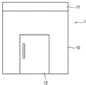
図1は、製造装置1の正面図である。図2は、正面から視た際の製造装置1の部分断面図である。製造装置1は、樹脂フィルム母材を延伸させて樹脂フィルムを製造するための装置である。製造装置1が延伸対象とする樹脂フィルム母材は特に限定されない。製造装置1が延伸対象とする樹脂フィルム母材は、特に限定されず、例えば、ポリ乳酸などの螺旋構造を有する高分子からなるもののような圧電性を有する樹脂フィルム母材であってもよい。
(Configuration of manufacturing apparatus 1)
FIG. 1 is a front view of the
図1及び図2に示すように、製造装置1は、製造装置本体10と、開閉可能なカバー11と、開閉可能な扉12とを備えている。カバー11は、図2にも示すように、製造装置本体10の上に配置されている。扉12は、製造装置本体10の正面に開閉可能に取り付けられている。この扉12を開けることによって、図2に示す制御装置13の操作が可能となる。
As shown in FIGS. 1 and 2, the
図2に示すように、製造装置本体10の内部には、加熱槽14と、冷却槽15と、制御室16とが区画形成されている。加熱槽14は、製造装置本体10の上部に形成されている。制御室16は、加熱槽14の下方に形成されている。冷却槽15は、加熱槽14の下方であって、制御室16の側方に形成されている。なお、加熱槽14と、冷却槽15と、制御室16とは、区画壁17aと、開閉可能な蓋17bとによって相互に区画されている。具体的には、制御室16と、加熱槽14及び冷却槽15とは、区画壁17aによって相互に区画されている。加熱槽14と冷却槽15とは、蓋17bによって区画されている。蓋17bが開けられると、加熱槽14と冷却槽15とは相互に連通する。
As shown in FIG. 2, a
加熱槽14には、加熱部としてのヒーター18と、加熱槽14内の温度を均一化するためのファン9とが配置されている。ヒーター18とファン9とは、制御室16に配置された制御装置13に接続されている。また、制御装置13には、加熱槽14内に配置された図示しない温度検出部が接続されている。制御装置13は、この温度検出部からの出力に基づいてヒーター18とファン9とを制御することによって、加熱槽14内の雰囲気温度を所望の温度に保持する。
The
なお、ファン9及びヒーター18の設置個数は特に限定されない。図2に示すように、ファン9及びヒーター18を各1個配置してもよいし、それぞれ複数配置してもよい。
In addition, the installation number of the
なお、温度検出部は、得に限定されず、例えば温度計により構成されていてもよい。 In addition, a temperature detection part is not limited to profit, For example, you may be comprised with the thermometer.
加熱槽14の温度は、延伸させる樹脂フィルム母材の特性などに応じて適宜設定することができる。通常、加熱槽14の温度は、延伸させる樹脂フィルム母材のガラス転移温度(Tg)よりも高い温度に設定される。樹脂フィルム母材がポリ乳酸製の場合は、例えば60〜100℃程度に設定される。
The temperature of the
製造装置1には、駆動部19が配置されている。駆動部19は、制御室16内に配置された駆動源としてのモーター20と、動力伝達部としてのギアボックス21とを備えている。モーター20は、駆動力を発生させる。ギアボックス21は、モーター20に接続されている。ギアボックス21は、出力軸22を備えている。ギアボックス21は、モーター20からの駆動力を変速して出力軸22から出力する。
A
出力軸22には、延伸ユニット30が着脱可能に接続される。延伸ユニット30は、加熱槽14において、樹脂フィルム母材を延伸させるためのものである。
The stretching
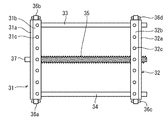
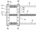
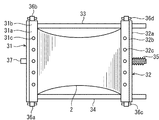
図3及び図4に示すように、延伸ユニット30は、ベースホルダ31と、移動ホルダ32と、ガイド33,34と、ねじ35と、ジョイント37と、車輪部36a〜36dとを備えている。なお、本実施形態において、ねじ35とジョイント37とは、ベースホルダ31と移動ホルダ32とを相対的に変位させる変位部を構成している。
As shown in FIGS. 3 and 4, the stretching
ベースホルダ31には、図2に示す樹脂フィルム母材2の一方端が固定される。ベースホルダ31は、ホルダ本体31aと、プレート31bと、接合部材としての複数のねじ31cとを備えている。プレート31bは、ホルダ本体31aの上面に、複数のねじ31cによって固定される。この複数のねじ31cをゆるめた状態で、樹脂フィルム母材2の一方端を挟み、ねじ31cを締めることによって、ベースホルダ31に樹脂フィルム母材2の一方端を挟持させることができる。
One end of the resin
移動ホルダ32は、ベースホルダ31と略並行に配置されている。移動ホルダ32には、樹脂フィルム母材2の他方端が固定される。移動ホルダ32は、ホルダ本体32aと、プレート32bと、接合部材としての複数のねじ32cとを備えている。プレート32bは、ホルダ本体32aの上面に、複数のねじ32cによって固定される。この複数のねじ32cをゆるめた状態で、樹脂フィルム母材2の他方端を挟み、ねじ32cを締めることによって、移動ホルダ32に樹脂フィルム母材2の他方端を挟持させることができる。
The moving
なお、ベースホルダ31と移動ホルダ32とは、樹脂フィルム母材2を挟持可能なものであれば特に限定されない。ベースホルダ31と移動ホルダ32とは、例えばクランプ機構を有するものや、空圧や油圧を利用した着脱機構を有するものであってもよい。
The
ベースホルダ31と移動ホルダ32との間には、ねじ35が配置されている。ねじ35は、ベースホルダ31及び移動ホルダ32の延びる方向と直交する方向に延びるように配置されている。すなわち、ねじ35は、樹脂フィルム母材2の延伸方向に延びるように配置されている。ねじ35の一方の端部は、ベースホルダ31に回転可能に設けられたジョイント37に接続されている。ねじ35は、このジョイント37と共に回転する。ジョイント37は、図2に示す駆動部19の出力軸22に対して着脱可能に接続される。
A
移動ホルダ32には、ねじ35のねじ山が螺合する図示しないねじ孔が形成されている。ねじ35は、このねじ孔に挿入されている。このため、ジョイント37と共にねじ35が第1の方向に回転すると、移動ホルダ32は、ベースホルダ31から離れる方向に、ガイド33,34に沿ってベースホルダ31に対して相対的に変位する。一方、ジョイント37と共にねじ35が第1の方向とは逆の第2の方向に回転すると、移動ホルダ32は、ベースホルダ31に近づく方向に、ガイド33,34に沿ってベースホルダ31に対して相対的に変位する。
The moving
図3に示すように、ベースホルダ31と移動ホルダ32との両端部のそれぞれには、車輪部36a〜36dが取り付けられている。図4に示すように、車輪部36a〜36dのそれぞれは、可動部38と、複数の車輪39aを有する車輪ユニット39とを備えている。車輪ユニット39は、可動部38によってベースホルダ31または移動ホルダ32に接続されている。可動部38は、ホルダ31,32に対して回転可能に取り付けられている。
As shown in FIG. 3,
図2に示すように、車輪部36a〜36dは、レール40に着脱可能に取り付けられている。レール40は、加熱槽14から冷却槽15に至っている。詳細には、レール40は、後述する冷却液15aの内部にまで至っている。延伸ユニット30は、このレール40上を加熱槽14と冷却槽15との間を変位可能となっている。
As shown in FIG. 2, the
冷却槽15には、冷却液15aが満たされている。ここで、冷却液15aの種類は特に限定されない。冷却液15aの種類は、樹脂フィルムの性質に応じて適宜選択することができる。冷却液15aは、例えば水であってもよいし、水に不凍液などを加えたものであってもよい。さらに、冷却液15aは、水以外の液体であってもよい。例えば、冷却液15aは、オイル、エタノール、イソプロピルアルコールなどであってもよい。
The
冷却槽15には、冷却装置41が配置されている。冷却装置41は、通常、冷却液15a内に配置されている。この冷却装置41によって、冷却液15aの冷却が行われる。なお、冷却液15aの冷却温度は、特に限定されない。冷却液15aの冷却温度は、樹脂フィルムの性質などに応じて適宜設定することができる。一般的には、冷却液15aの冷却温度は低い方が好ましく、例えば、0〜−20度程度に設定される。
A cooling
(樹脂フィルムの製造工程)
以下、主として図2及び図5を参照しながら樹脂フィルムの延伸工程について説明する。
(Production process of resin film)
Hereinafter, the stretching process of the resin film will be described mainly with reference to FIGS. 2 and 5.
まず、延伸ユニット30に樹脂フィルム母材2が設置される。具体的には、樹脂フィルム母材2の一方端をベースホルダ31に挟持させると共に、他方端を移動ホルダ32に挟持させる。
First, the resin
そして、樹脂フィルム母材2が設置された延伸ユニット30を加熱槽14内に配置し、延伸ユニット30のジョイント37と、駆動部19の出力軸22とを接続させる。
And the extending | stretching
その状態で、ヒーター18及びファン9を駆動させ、加熱槽14を樹脂フィルム母材2の延伸に適した温度にまで加温する。例えば、樹脂フィルム母材2がポリ乳酸により形成されている場合は、加熱槽14を60〜180℃程度に加温する。
In this state, the
加熱槽14を所定の温度にまで加温した後、延伸工程が行われる。延伸工程では、駆動部19を駆動させることによって、ベースホルダ31に対して移動ホルダ32を相対的に変位させ、樹脂フィルム母材2を延伸させる。ここで、樹脂フィルム母材2の延伸倍率は特に限定されない。樹脂フィルム母材2の延伸倍率は、樹脂フィルム母材2の性質に応じて適宜設定することができる。樹脂フィルム母材2がポリ乳酸製である場合は、延伸倍率は、例えば2〜4倍程度に設定することができる。
After heating the
延伸工程の完了後、冷却工程が行われる。冷却工程は、延伸工程において、延伸されたフィルム母材毎に行われる。具体的には、延伸工程が完了すると、自動または手動で、蓋17bが開けられると共に、出力軸22からジョイント37が切り離される。これによって、図5に示すように、延伸された樹脂フィルム母材2が搭載された延伸ユニット30が加熱槽14から冷却槽15へとレール40上を移動する。その結果、延伸された樹脂フィルム母材2は延伸ユニット30と共に冷却液15a内に挿入されることとなる。ここで、冷却液15aは、冷却装置41によって予め所定の温度にまで冷却されている。このため、延伸された樹脂フィルム母材2は、冷却液15a内に挿入されることによって、均一に急冷される。
A cooling process is performed after completion | finish of an extending | stretching process. The cooling step is performed for each stretched film base material in the stretching step. Specifically, when the stretching process is completed, the
このように、樹脂フィルム母材2毎に、延伸工程と、冷却工程とを繰り返すことにより、複数の樹脂フィルムを作製することができる。
Thus, a plurality of resin films can be produced by repeating the stretching process and the cooling process for each resin
なお、レール40は、図2に示すように、途中部において屈曲されているが、車輪部36a〜36dには、回転可能にホルダ31,32に取り付けられた可動部38が設けられているため、延伸ユニット30は、屈曲したレール40に沿って変位することができる。
As shown in FIG. 2, the
また、延伸ユニット30の移動は、手動により行ってもよい。また、延伸ユニット30にモーターなどを配置して、延伸ユニット30を自走させてもよい。
Further, the stretching
以上説明したように、本実施形態によれば、延伸後の樹脂フィルム母材2は、冷却液15a内に挿入される。このため、例えば樹脂フィルム母材を空冷させるときなどと比較して、急速に冷却させることができる。従って、配向度の高い樹脂フィルムの製造が可能となる。
As described above, according to the present embodiment, the stretched resin
また、樹脂フィルム母材を空冷させる場合と比較して、樹脂フィルム母材を均一に冷却させることも可能となる。従って、品質上、ムラの少ない樹脂フィルムの製造が可能となる。例えば、樹脂フィルム母材がポリ乳酸を含み、圧電性を有するものである場合、圧電性のムラが少ない樹脂フィルムの製造が可能となる。 Moreover, compared with the case where the resin film base material is air-cooled, the resin film base material can be cooled uniformly. Accordingly, it is possible to manufacture a resin film with less unevenness in quality. For example, when the resin film base material contains polylactic acid and has piezoelectricity, it is possible to manufacture a resin film with little piezoelectric nonuniformity.
ところで、通常、延伸後の樹脂フィルム母材を冷却させる場合、作業者が、樹脂フィルム母材をホルダから外して、またはホルダごと、別の場所に配置された冷却槽まで移動させる必要がある。それに対して、本実施形態によれば、延伸ユニット30がレール40上を移動することにより延伸された樹脂フィルム母材2が冷却液15a内に挿入される。従って、作業者にかかる負荷を少なくすることができる。
By the way, normally, when cooling the resin film base material after extending | stretching, it is necessary for an operator to remove the resin film base material from a holder, or to move to the cooling tank arrange | positioned in another place with the holder. On the other hand, according to the present embodiment, the resin
なお、本実施形態の製造装置1は、樹脂フィルムの大量生産にももちろん用いられるものであるが、少量の樹脂フィルムの製造に特に好適である。
In addition, although the
(変形例)
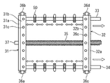
図6及び図7は、本変形例における延伸ユニット30の平面図である。図6及び図7に示すように、複数のネッキング抑制用の固定具50を設けてもよい。複数の固定部50は、ガイド33,34のそれぞれにねじ35の延びる方向に変位可能に設けられている。詳細には、図7に示すように、複数の固定具50は、移動ホルダ32の移動に伴って、隣接する固定具50の間隔が広がるように設けられている。
(Modification)
6 and 7 are plan views of the stretching
本変形例の場合、延伸ユニット30のベースホルダ31と移動ホルダ32とに樹脂フィルム母材2を固定すると共に、樹脂フィルム母材2の両側部を複数の固定具50によって固定する。その後、移動ホルダ32をベースホルダ31に対して相対的に変位させる。
In the case of this modification, the resin
例えば、上記実施形態のように、固定具50を設けていない場合は、図9に示すように、樹脂フィルム母材2を延伸させることによって、延伸方向における略中央部の幅が狭くなる。いわゆるネッキングが発生する。従って、樹脂フィルムの延伸方向の端部と中央部とで配向度にばらつきが生じる。
For example, when the
それに対して、本変形例では、固定具50が設けられているため、図8に示すように、延伸方向における略中央部の幅が狭くなることが抑制される。すなわち、ネッキングの発生を抑制することができる。その結果、得られる樹脂フィルムの配向度のばらつきを抑制することができる。
On the other hand, in this modification, since the
なお、固定具50は、ガイド33,34に対して延伸方向に変位可能であってもよい。
The
1…製造装置
9…ファン
10…製造装置本体
11…カバー
12…扉
13…制御装置
14…加熱槽
15…冷却槽
15a…冷却液
16…制御室
17a…区画壁
17b…蓋
18…ヒーター
19…駆動部
20…モーター
21…ギアボックス
22…出力軸
30…延伸ユニット
31…ベースホルダ
31a…ホルダ本体
31b…プレート
32…移動ホルダ
32a…ホルダ本体
32b…プレート
33,34…ガイド
36a〜36d…車輪部
37…ジョイント
38…可動部
39…車輪ユニット
39a…車輪
40…レール
41…冷却装置
50…固定具
DESCRIPTION OF
Claims (4)
樹脂フィルム母材を延伸可能な温度にまで加熱するための加熱槽と、
冷却液が溜められた冷却槽と、
前記加熱槽内から前記冷却槽に至るレールと、
前記レール上に前記加熱槽と前記冷却槽との間を移動可能に配置され、前記加熱された樹脂フィルム母材を延伸させる延伸ユニットとを備える樹脂フィルムの製造装置。 An apparatus for producing a resin film,
A heating tank for heating the resin film base material to a temperature at which it can be stretched;
A cooling tank in which a coolant is stored;
A rail from the heating tank to the cooling tank;
An apparatus for producing a resin film, comprising: a stretching unit which is arranged on the rail so as to be movable between the heating tank and the cooling tank and stretches the heated resin film base material.
前記変位部を駆動させる駆動部をさらに備え、
前記駆動部と前記変位部とは着脱可能に接続される、請求項1に記載の樹脂フィルムの製造装置。 The stretching unit includes a base holder to which one end of a resin film is fixed, a moving holder to which the other end of the resin film is fixed, and a displacement portion that relatively displaces the moving holder and the base holder. ,
A drive unit for driving the displacement unit;
The said drive part and the said displacement part are manufacturing apparatuses of the resin film of Claim 1 connected so that attachment or detachment is possible.
加熱された樹脂フィルム母材を延伸させる延伸工程と、
前記延伸された樹脂フィルム母材全体を冷却液が溜められた冷却槽内に挿入して冷却させることにより樹脂フィルムを得る冷却工程と
を備える樹脂フィルムの製造方法。 A method for producing a resin film, comprising:
A stretching step of stretching the heated resin film base material;
The stretching process for the preparation of dendritic fat film Ru and a cooling step to obtain a resin film by the entire resin film base material was inserted into the coolant pooled in cooling bath to cool.
Priority Applications (1)
| Application Number | Priority Date | Filing Date | Title |
|---|---|---|---|
| JP2008099135A JP5131003B2 (en) | 2008-04-07 | 2008-04-07 | Resin film manufacturing apparatus and method |
Applications Claiming Priority (1)
| Application Number | Priority Date | Filing Date | Title |
|---|---|---|---|
| JP2008099135A JP5131003B2 (en) | 2008-04-07 | 2008-04-07 | Resin film manufacturing apparatus and method |
Publications (2)
| Publication Number | Publication Date |
|---|---|
| JP2009248445A JP2009248445A (en) | 2009-10-29 |
| JP5131003B2 true JP5131003B2 (en) | 2013-01-30 |
Family
ID=41309579
Family Applications (1)
| Application Number | Title | Priority Date | Filing Date |
|---|---|---|---|
| JP2008099135A Expired - Fee Related JP5131003B2 (en) | 2008-04-07 | 2008-04-07 | Resin film manufacturing apparatus and method |
Country Status (1)
| Country | Link |
|---|---|
| JP (1) | JP5131003B2 (en) |
Families Citing this family (3)
| Publication number | Priority date | Publication date | Assignee | Title |
|---|---|---|---|---|
| WO2015001956A1 (en) * | 2013-07-04 | 2015-01-08 | 三井化学株式会社 | Film and polymeric piezoelectric material |
| KR101721636B1 (en) * | 2016-07-21 | 2017-03-30 | 주식회사 지엔티엔에스 | High Temperature Single-Axis Precise Control Stretching Machine for Film |
| KR101678871B1 (en) * | 2016-08-24 | 2016-12-06 | 이승원 | Device for leather stretching to separating distance of bar |
Family Cites Families (11)
| Publication number | Priority date | Publication date | Assignee | Title |
|---|---|---|---|---|
| US3579718A (en) * | 1968-10-17 | 1971-05-25 | Sierracin Corp | Apparatus for stretching sheet material |
| EP0022278B1 (en) * | 1979-04-11 | 1984-02-08 | Agfa-Gevaert N.V. | Method and apparatus for longitudinally stretching a substantially amorphous polyethylene terephthalate film |
| JPS55158936A (en) * | 1979-05-26 | 1980-12-10 | Tousoku Seimitsu Kogyo Kk | Chuck system for biaxial stretching device |
| JPS5644627A (en) * | 1979-09-18 | 1981-04-23 | Mitsubishi Plastics Ind Ltd | Molding of plastic sheet |
| JPS5695639A (en) * | 1979-12-28 | 1981-08-03 | Toshio Kunugi | Manufacture of superreinforced uniaxially oriented film |
| JPS5991032A (en) * | 1982-11-16 | 1984-05-25 | Japan Synthetic Rubber Co Ltd | Manufacture of high-molecular piezoelectric film |
| JPS6132169A (en) * | 1984-07-23 | 1986-02-14 | Ricoh Co Ltd | Word extracting system |
| JPS61114836A (en) * | 1984-11-09 | 1986-06-02 | Teijin Ltd | Biaxialorientation tester |
| JP2000006236A (en) * | 1998-06-29 | 2000-01-11 | Mitsubishi Chemicals Corp | Thermoplastic resin stretched pipe with socket |
| JP2001214013A (en) * | 1999-11-24 | 2001-08-07 | Yupo Corp | Resin drawn film and method for producing the same |
| JP2004017367A (en) * | 2002-06-13 | 2004-01-22 | Sumitomo Chem Co Ltd | Biaxial stretching mechanism, biaxial stretching testing machine and biaxial stretching machine having the biaxial stretching mechanism |
-
2008
- 2008-04-07 JP JP2008099135A patent/JP5131003B2/en not_active Expired - Fee Related
Also Published As
| Publication number | Publication date |
|---|---|
| JP2009248445A (en) | 2009-10-29 |
Similar Documents
| Publication | Publication Date | Title |
|---|---|---|
| JP5131003B2 (en) | Resin film manufacturing apparatus and method | |
| US7602469B2 (en) | Cooling apparatus and method for manufacturing liquid crystal display device using the same | |
| JP2019524485A (en) | Control device for forming and / or processing resin foil and resin foil molding control method | |
| WO2007052708A1 (en) | Process for producing glass bar | |
| CN206387749U (en) | A kind of heat aging test chamber | |
| JP2012528068A (en) | Laser scoring of glass at high temperatures | |
| US7524182B2 (en) | Blowing mechanism | |
| JPH10194770A (en) | Wire drawing furnace for optical fiber | |
| US20040055337A1 (en) | Apparatus and process for air-cooling and tempering a glass sheet | |
| WO2015161525A1 (en) | Method and device for manufacturing curved liquid crystal display | |
| KR100945912B1 (en) | Device for heat treatment of semiconductor device | |
| JPS5936851B2 (en) | Manufacturing method of polyester film | |
| JP7513410B2 (en) | Method for manufacturing retardation film | |
| CN101052594A (en) | Method and apparatus for heating sheets of glass | |
| US4687615A (en) | Method of producing biaxially oriented tubular polyetheretherketone films | |
| CN215218382U (en) | Film tensile testing machine | |
| CN221497090U (en) | Transverse stretching machine for BOPP film production | |
| JP2004160819A (en) | Manufacturing method for optical film | |
| KR100750460B1 (en) | Aluminum alloy pipe | |
| CN101050485A (en) | Method and equipment for plasticity heat treatment to recover composite boards of explosive welding | |
| KR102064511B1 (en) | Shutter apparatus and substrate treatment apparatus comprising the same | |
| CN215095596U (en) | Improvement device of film thickness homogeneity | |
| KR101828436B1 (en) | Mold cooling apparatus using a plurality of the cooling pipe | |
| CN221112942U (en) | Polyimide film heat treatment wind channel | |
| CN204417554U (en) | Allow iron plate capotasto thermal treatment unit |
Legal Events
| Date | Code | Title | Description |
|---|---|---|---|
| A621 | Written request for application examination |
Free format text: JAPANESE INTERMEDIATE CODE: A621 Effective date: 20110317 |
|
| A977 | Report on retrieval |
Free format text: JAPANESE INTERMEDIATE CODE: A971007 Effective date: 20120718 |
|
| A131 | Notification of reasons for refusal |
Free format text: JAPANESE INTERMEDIATE CODE: A131 Effective date: 20120724 |
|
| A521 | Request for written amendment filed |
Free format text: JAPANESE INTERMEDIATE CODE: A523 Effective date: 20120911 |
|
| TRDD | Decision of grant or rejection written | ||
| A01 | Written decision to grant a patent or to grant a registration (utility model) |
Free format text: JAPANESE INTERMEDIATE CODE: A01 Effective date: 20121009 |
|
| A01 | Written decision to grant a patent or to grant a registration (utility model) |
Free format text: JAPANESE INTERMEDIATE CODE: A01 |
|
| A61 | First payment of annual fees (during grant procedure) |
Free format text: JAPANESE INTERMEDIATE CODE: A61 Effective date: 20121022 |
|
| FPAY | Renewal fee payment (event date is renewal date of database) |
Free format text: PAYMENT UNTIL: 20151116 Year of fee payment: 3 |
|
| R150 | Certificate of patent or registration of utility model |
Free format text: JAPANESE INTERMEDIATE CODE: R150 Ref document number: 5131003 Country of ref document: JP Free format text: JAPANESE INTERMEDIATE CODE: R150 |
|
| LAPS | Cancellation because of no payment of annual fees |
