JP4821397B2 - Air-cooled absorption refrigeration equipment absorber - Google Patents
Air-cooled absorption refrigeration equipment absorber Download PDFInfo
- Publication number
- JP4821397B2 JP4821397B2 JP2006084428A JP2006084428A JP4821397B2 JP 4821397 B2 JP4821397 B2 JP 4821397B2 JP 2006084428 A JP2006084428 A JP 2006084428A JP 2006084428 A JP2006084428 A JP 2006084428A JP 4821397 B2 JP4821397 B2 JP 4821397B2
- Authority
- JP
- Japan
- Prior art keywords
- absorber
- air
- absorption
- cooled
- solution
- Prior art date
- Legal status (The legal status is an assumption and is not a legal conclusion. Google has not performed a legal analysis and makes no representation as to the accuracy of the status listed.)
- Expired - Fee Related
Links
Images
Classifications
-
- Y—GENERAL TAGGING OF NEW TECHNOLOGICAL DEVELOPMENTS; GENERAL TAGGING OF CROSS-SECTIONAL TECHNOLOGIES SPANNING OVER SEVERAL SECTIONS OF THE IPC; TECHNICAL SUBJECTS COVERED BY FORMER USPC CROSS-REFERENCE ART COLLECTIONS [XRACs] AND DIGESTS
- Y02—TECHNOLOGIES OR APPLICATIONS FOR MITIGATION OR ADAPTATION AGAINST CLIMATE CHANGE
- Y02A—TECHNOLOGIES FOR ADAPTATION TO CLIMATE CHANGE
- Y02A30/00—Adapting or protecting infrastructure or their operation
- Y02A30/27—Relating to heating, ventilation or air conditioning [HVAC] technologies
-
- Y—GENERAL TAGGING OF NEW TECHNOLOGICAL DEVELOPMENTS; GENERAL TAGGING OF CROSS-SECTIONAL TECHNOLOGIES SPANNING OVER SEVERAL SECTIONS OF THE IPC; TECHNICAL SUBJECTS COVERED BY FORMER USPC CROSS-REFERENCE ART COLLECTIONS [XRACs] AND DIGESTS
- Y02—TECHNOLOGIES OR APPLICATIONS FOR MITIGATION OR ADAPTATION AGAINST CLIMATE CHANGE
- Y02B—CLIMATE CHANGE MITIGATION TECHNOLOGIES RELATED TO BUILDINGS, e.g. HOUSING, HOUSE APPLIANCES OR RELATED END-USER APPLICATIONS
- Y02B30/00—Energy efficient heating, ventilation or air conditioning [HVAC]
- Y02B30/62—Absorption based systems
Landscapes
- Sorption Type Refrigeration Machines (AREA)
Description
本願発明は、間接空冷方式を採用した空冷吸収式冷凍装置の吸収器の構造に関するものである。 The present invention relates to the structure of an absorber of an air-cooled absorption refrigeration apparatus employing an indirect air-cooling method.
従来の一般的な空冷吸収式冷凍装置の吸収器は、例えば図7に示すように、吸収器30を、多数の伝熱フィン9,9・・・を備えた複数本の伝熱管3a,3a・・・(溶液流入口3c,3c・・・)と、吸収溶液分配トレイ11とから構成し、溶液循環路13に設けた冷媒循環ポンプPを介して吸収器30の伝熱管3a,3a・・・内の冷媒通路3b,3b・・・に吸収溶液を流し、同溶液通路3b,3b・・・部分で蒸発器側からの冷媒蒸気を吸収させながら、吸収溶液を伝熱管3a,3a外周のファンFの冷却風により冷却される空冷フィン9,9・・・で冷却する直接空冷方式であり、吸収器30では、冷媒蒸気の吸収と吸収溶液の冷却とを同時に行うための気液界面の拡大が重要であるため、小型化への制約が大きい。
For example, as shown in FIG. 7, an absorber of a conventional general air-cooled absorption refrigeration apparatus includes an
例えば、吸収溶液分配トレイ11を含めた上下吸収器ヘッダー部分でのスペース、蒸気圧損考慮のための大口径管の使用、冷媒蒸気の流速制限に起因して蒸発器との連絡管が太くなる等である。 For example, the space in the upper and lower absorber headers including the absorbent solution distribution tray 11, the use of a large-diameter pipe for considering vapor pressure loss, the connection pipe with the evaporator becoming thick due to the restriction of the flow rate of the refrigerant vapor, etc. It is.
また、コスト的にも、溶接による接続箇所があるため、小型機では割高となる。 Moreover, since there exists the connection location by welding also in terms of cost, it becomes expensive in a small machine.
これに対して、例えば図8に示すように、溶液ポンプPにより溶液循環路12を介して筒状の吸収器30内に流入する吸収溶液を伝熱管15a,15a・・・、伝熱フィン17,17・・・、上下ヘッダ16b,16a、ファンF等よりなる空冷式の冷却器15にて過冷却することによって、吸収器30内では単に冷媒蒸気のみを吸収させ、吸収熱は同過冷却された吸収溶液の顕熱で取り去るだけの間接(溶液分離冷却)空冷方式があり、同方式では、冷却手段が不要となるだけ吸収器30部分が小型化されるので、小型の空冷吸収器では有利である。
On the other hand, for example, as shown in FIG. 8, the absorption solution flowing into the
そこで、従来例の中には、そのような特徴を活用し、吸収溶液噴霧方式(図8の符号14参照)による冷媒蒸気の吸収方法を採用した空冷吸収式冷凍装置の吸収器がある(特許文献1参照)。
Therefore, in the conventional example, there is an absorber of an air-cooled absorption refrigeration apparatus that utilizes such a feature and adopts an absorption solution spray method (see
しかし、同噴霧方式では吸収液噴霧ノズル14の目詰まりや、溶液ポンプの吐出ヘッド増大による消費電力の増加等の問題がある。
However, the spray system has problems such as clogging of the absorbing
本願発明は、このような問題を解決するためになされたもので、吸収器の冷却方式を、上記吸収器に流入する吸収溶液を空冷冷却器にて過冷却した溶液の顕熱で取り去るだけの間接空冷方式とする一方、吸収器の吸収部に液膜流下式のプレート構造を採用するとともに、その上部にプレートに吸収溶液を均等に分配するための吸収溶液分配トレイを設け、当該プレートの両面に上記過冷却後の吸収溶液を液膜状態で流すことによって、冷媒蒸気の吸収を促進させるようにした高効率かつ小型、低コストの空冷吸収器を提供することを目的とするものである。 The present invention has been made to solve such problems, and the cooling method of the absorber is simply removed by the sensible heat of the solution supercooled by the air-cooled cooler. While adopting an indirect air cooling system, a liquid film flow-down plate structure is adopted for the absorption part of the absorber, and an absorption solution distribution tray for evenly distributing the absorption solution to the plate is provided on the upper part, and both surfaces of the plate are Another object of the present invention is to provide a high-efficiency, small, and low-cost air-cooled absorber that promotes absorption of refrigerant vapor by flowing the supercooled absorption solution in a liquid film state.
本願発明は、同目的を達成するために、次のような課題解決手段を備えて構成されている。 In order to achieve the same object, the present invention is configured with the following problem solving means.
(1) 第1の課題解決手段
この発明の第1の課題解決手段は、吸収器に入る吸収溶液を空冷冷却器にて過冷却し、蒸発器と一体で本体ケーシング内に収められた吸収器内で、蒸発器で蒸発させた冷媒蒸気を単に吸収させるだけで、吸収時に発生する吸収熱を過冷却された吸収溶液の顕熱で間接的に冷却する間接空冷方式を採用した吸収器を備えた空冷吸収式冷凍装置において、前記蒸発器および前記吸収器の各々上部に、冷媒および吸収溶液を均等に分配するための冷媒分配トレイおよび吸収溶液分配トレイを各々設けるとともに、前記蒸発器を、内部に被冷却体通路を形成したプレート熱交換器として、表面に冷媒を流下させて蒸発させることで内部の被冷却流体を冷却するように構成する一方、前記吸収器を、1枚の平面プレートの両面を溶液が液膜状態で流下するように構成したことを特徴としている。
(1) First Problem Solving Means The first problem solving means of the present invention is an absorber in which an absorption solution entering an absorber is supercooled by an air-cooled cooler, and is stored in a main body casing integrally with an evaporator. It has an absorber that employs an indirect air cooling system that simply absorbs the refrigerant vapor evaporated in the evaporator and indirectly cools the absorption heat generated during absorption with the sensible heat of the supercooled absorption solution. In the air-cooled absorption refrigeration apparatus, a refrigerant distribution tray and an absorption solution distribution tray for evenly distributing the refrigerant and the absorption solution are respectively provided on the evaporator and the absorber, and the evaporator A plate heat exchanger having a body passage to be cooled is configured to cool a fluid to be cooled by allowing a refrigerant to flow down on the surface and evaporating it, while the absorber is formed on one flat plate . Both The solution is characterized by being configured so as to flow down in a liquid film state.
このような構成によれば、吸収器を伝熱管ではなく1枚の平面プレートよりなるプレート部材で構成していることから、蒸発器との一体化も可能となり、小型化、低コスト化が可能となる。 According to such a configuration, the absorber because it is constituted by the plate member made of a single planar plate rather than the heat transfer tube, it becomes possible integration of the evaporator, downsizing, cost reduction can be It becomes.
また、同1枚の平面プレートの両面を吸収溶液が液膜状態で流下する液膜流下構造を採用しているから、従来例のような吸収溶液噴霧ノズルを使用するものと異なって、目詰まりや、溶液ポンプの吐出ヘッドの増大等がなく、消費電力も少ない。 Further, different from that absorbed solution on both sides of the same one plane plates because they employ a liquid film flowing down structure flows down in a liquid film state, using the absorption solution spray nozzle as in the prior art, clogging In addition, there is no increase in the discharge head of the solution pump, and power consumption is low.
また、吸収器の上部に、吸収溶液を均等に分配するための吸収溶液分配トレイを設けるとともに、前記蒸発器を、内部に被冷却体通路を形成したプレート熱交換器として、表面に冷媒を流下させて蒸発させることで内部の被冷却流体を冷却するように構成して、フラットなプレート面に均一に吸収溶液が流されるようにしているため、より均一な液膜化による吸収効率向上、冷却部不要による可及的な小型化を図ることができる。 In addition , an absorbent solution distribution tray for evenly distributing the absorbent solution is provided at the upper part of the absorber, and the evaporator is used as a plate heat exchanger in which a passage to be cooled is formed. Since the liquid to be cooled is cooled by evaporating the liquid, the absorption solution is made to flow uniformly on the flat plate surface. The size can be reduced as much as possible by eliminating the need for parts.
さらに、吸収溶液冷却用の空冷冷却器には、汎用の伝熱管や熱交換器が使用できるため、大きくコストが低下する。 Furthermore, since a general-purpose heat transfer tube or heat exchanger can be used for the air-cooled cooler for cooling the absorbing solution, the cost is greatly reduced.
(2) 第2の課題解決手段
この発明の第2の課題解決手段は、上記第1の課題解決手段の構成において、平面プレート部は、コルゲーションタイプの平面プレートよりなっている。
(2) Second Problem Solving Means According to a second problem solving means of the present invention, in the configuration of the first problem solving means, the flat plate portion is a corrugated flat plate.
このような構成によれば、平面プレートとして効果的に液膜化が図られることはもちろん、液膜部の面積拡大により、より有効に吸収性能を向上させることができる。 According to such a configuration, a liquid film can be effectively formed as a flat plate, and the absorption performance can be improved more effectively by expanding the area of the liquid film portion.
(3) 第3の課題解決手段
この発明の第3の課題解決手段は、上記第1又は第2の課題解決手段の構成において、平面プレートのプレート部の表面に、液膜拡散手段を設けて構成されている。
(3) Third Problem Solving Means According to a third problem solving means of the present invention, in the configuration of the first or second problem solving means, a liquid film diffusing means is provided on the surface of the plate portion of the flat plate. It is configured.
このような構成によれば、プレート部表面の液膜を有効に拡散させ、下部側への流下を可及的に均一することができる。その結果、より有効に吸収性能を向上させることができる。 According to such a configuration, the liquid film on the surface of the plate portion can be effectively diffused, and the flow down to the lower side can be made as uniform as possible. As a result, the absorption performance can be improved more effectively.
この液膜拡散手段としては、例えばプレート部の表面にディンプルや凹凸の溝を付けたり、さらに金網等を取り付けることなどが考えられる。 As the liquid film diffusing means, for example, it is conceivable to add dimples or concave and convex grooves on the surface of the plate portion, or to attach a wire mesh or the like.
(4) 第4の課題解決手段
この発明の第4の課題解決手段は、上記第2の課題解決手段の構成において、コルゲーションタイプの平面プレートのプレート部には、多数の穴が設けられている。
(4) Fourth Problem Solving Means According to a fourth problem solving means of the present invention, in the configuration of the second problem solving means, a plate portion of a corrugation type flat plate is provided with a number of holes. .
このような構成によれば、平面部での吸収液の液膜化と多数の穴を介した液滴化とが可能となり、それらの両方で冷媒蒸気の吸収性能を一層大きく向上させることができる。 According to such a configuration, it is possible to form a liquid film of the absorbing liquid on the flat portion and to form droplets through a large number of holes, and both of them can further improve the absorption performance of the refrigerant vapor. .
この場合、穴あきプレートとしては、例えばパンチングプレートやエキスパンドメタルなどの採用が可能であり、そのようにすると、容易に加工製作することができる。 In this case, for example, a punching plate or an expanded metal can be used as the perforated plate, and by doing so, it can be easily processed and manufactured.
以上の結果、本願発明によると、冷媒蒸気吸収性能の高い吸収器を低コスト、かつコンパクトに提供することが可能となるという効果がある。 As a result, according to the present invention, there is an effect that it is possible to provide a high absorber of refrigerant vapor absorption performance low cost and compact.
また、1枚の平面プレートの両面を吸収溶液が液膜状態で流下する液膜流下構造を採用しているから、従来例のような吸収溶液噴霧ノズルを使用するものと異なって、目詰まりや、溶液ポンプの吐出ヘッドの増大等がなく、消費電力も少ないという効果もある。In addition, since the liquid film flow structure in which the absorbing solution flows down in a liquid film state on both surfaces of one flat plate is used, unlike the case of using the absorbing solution spray nozzle as in the conventional example, clogging and There is also an effect that there is no increase in the discharge head of the solution pump and the power consumption is small.
また、吸収器の上部に、吸収溶液を均等に分配するための吸収溶液分配トレイを設けるとともに、前記蒸発器を、内部に被冷却体通路を形成したプレート熱交換器として、表面に冷媒を流下させて蒸発させることで内部の被冷却流体を冷却するように構成して、フラットなプレート面に均一に吸収溶液が流されるようにしているため、より均一な液膜化による吸収効率向上、冷却部不要による可及的な小型化を図ることができるという効果もある。 In addition, an absorbent solution distribution tray for evenly distributing the absorbent solution is provided at the upper part of the absorber, and the evaporator is used as a plate heat exchanger in which a passage to be cooled is formed. Since the liquid to be cooled is cooled by evaporating the liquid, the absorption solution is made to flow uniformly on the flat plate surface. There is also an effect that it is possible to reduce the size as much as possible because no part is required .
さらに、吸収溶液冷却用の空冷冷却器には、汎用の伝熱管や熱交換器が使用できるため、大きくコストが低下するという効果もある。Furthermore, since a general-purpose heat transfer tube or heat exchanger can be used for the air-cooled cooler for cooling the absorbing solution, there is an effect that the cost is greatly reduced.
(最良の実施の形態1)
図1〜図3は、本願発明の最良の実施の形態1に係る空冷吸収式冷凍装置の吸収器の構成を示している。
(Best Embodiment 1)
1 to 3 show the configuration of an absorber of an air-cooled absorption refrigeration apparatus according to the
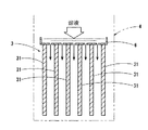
先ず図1は、同吸収器3に対して蒸発器2を箱型の本体ケーシング4内に一体化した吸収器および蒸発器ユニット1部分の構成を箱型の本体ケーシング4の一部を切り欠いて示している。
First, FIG. 1 shows a configuration of an absorber and an
この実施の形態の場合、吸収器3に入るLiBr吸収溶液を図示しない空冷冷却器(図8参照)にて過冷却し、蒸発器2と一体で本体ケーシング1内に収められた吸収器3内で、蒸発器2で蒸発させた冷媒蒸気を単に吸収させるだけで、吸収時に発生する吸収熱を過冷却された吸収溶液の顕熱で間接的に冷却する間接(溶液分離冷却)空冷方式が採用されている。
In the case of this embodiment, the LiBr absorption solution entering the
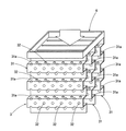
そして、蒸発器2、吸収器3の各々上部には、図2、図3に示すように、冷媒、吸収溶液を均等に分配するための冷媒分配トレイ5、吸収溶液分配トレイ6を各々設け、蒸発器2は内部に被冷却体通路21aを形成した菱形構造のプレート熱交換器21,21・・・とし、表面に冷媒を液膜で流下させて蒸発させることで内部の被冷却流体(冷水等)を冷却するようになっている一方、吸収器3は単一の平面プレート31,31・・・の両面を溶液が液膜状態で垂直に流下することで、冷媒蒸気の吸収をより効果的に促進させるようになっている。
Then, as shown in FIGS. 2 and 3, a
なお、図1中の7は希溶液の出口、8aは冷水の入り口、8bは冷水の出口を示している。 In FIG. 1, 7 is an outlet for dilute solution, 8a is an inlet for cold water, and 8b is an outlet for cold water.
このような構成によれば、吸収器3の吸収部を伝熱管ではなくプレート部材で構成することができるようになり、蒸発器2との一体化も可能となり、小型化、低コスト化が可能となる。
According to such a configuration, the absorption part of the
また、従来例のような吸収溶液噴霧ノズル(図8中の14参照)を使用するものと異なって、目詰まりや、溶液ポンプの吐出ヘッドの増大等がなく、消費電力も少ない。 Further, unlike the case of using an absorbing solution spray nozzle (see 14 in FIG. 8) as in the conventional example, there is no clogging, an increase in the discharge head of the solution pump, and the power consumption is small.
また、吸収溶液冷却用の空冷冷却器は、汎用の伝熱管や熱交換器が使用できるため(図8の構成参照)、大きくコストが低下する。 In addition, since the air-cooled cooler for cooling the absorbing solution can use a general-purpose heat transfer tube or heat exchanger (see the configuration in FIG. 8), the cost is greatly reduced.
また、吸収器3の吸収部はフラットな平面プレート31,31・・・よりなっている。
Moreover, the absorption part of the
このような構成によると、液膜化による吸収効率向上、冷却部不要による可及的な小型化を図ることができる。 According to such a configuration, it is possible to improve the absorption efficiency by forming a liquid film and to reduce the size as much as possible without the need for a cooling unit.
それらの結果、冷媒蒸気吸収性能の高い吸収器を低コスト、かつコンパクトに提供することが可能となる。 As a result, it is possible to provide an absorber having high refrigerant vapor absorption performance at a low cost and in a compact manner.
(変形例1)
なお、以上のように構成した場合において、上記フラットな平面プレート31,31・・・の表面には、液膜を有効に拡散させ、その下部への流下状態をできるだけ均一化にするように、例えばディンプルや凹凸の溝を付けたり、さらに金網等を取り付けることもできる。
(Modification 1)
In the case of the above configuration, the liquid film is effectively diffused on the surfaces of the flat
(最良の実施の形態2)
次に図4および図5は、本願発明の最良の実施の形態2に係る空冷吸収式冷凍装置の吸収器の構造を示している。
(Best Mode 2)
Next, FIGS. 4 and 5 show the structure of the absorber of the air-cooled absorption refrigeration apparatus according to the second preferred embodiment of the present invention.
この実施の形態は、上記最良の実施の形態1の構成における吸収器3の各平面プレート31,31・・・を、例えば図4に示すような上下方向に所定の長さのコルゲーション構造に曲成するとともに、その表面31a,31a・・・に多数の穴32,32・・・を設け、平面部を上方側から下方側に流下する液膜化された吸収溶液をさらに多数の穴32,32・・・を介して効果的に液滴化させながら順次上段から下段に流下させるようにしたことを特徴とするものである。
In this embodiment, the
このような構成によると、液膜形成のためのプレート部の面積が大きく拡大され、液膜面積が大きく拡大されるとともに、それらの広い範囲で上段側から下段側への液滴化が生じ、それらの両方の作用で冷媒蒸気の吸収性能が一段と大きく向上する。 According to such a configuration, the area of the plate portion for liquid film formation is greatly enlarged, the liquid film area is greatly enlarged, and droplet formation from the upper stage side to the lower stage occurs in those wide ranges, Both of these effects greatly improve the refrigerant vapor absorption performance.
(変形例1)
なお、以上のように構成した場合においても、上記多数の穴32,32・・・を有するコルゲーション構造の平面プレート31,31・・・の表面に、液膜を拡散させ、その下部への流下状態をできるだけ均一化にするように、例えばディンプルや凹凸の溝を付けたり、さらに金網等を取り付けることができる。
(Modification 1)
Even when configured as described above, the liquid film is diffused on the surface of the
(変形例2)
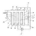
また、以上のように、吸収器3の平面プレート31,31・・・を、多数の穴32,32・・・を備えたコルゲーション構造のものに形成した場合において、例えば図6に示すように、上記吸収器3と蒸発器4は横方向に並設して一体化することもできる。
(Modification 2)
Further, as described above, when the
このような構成によっても、上記図4のものと全く同様の作用効果を実現することができる。 Even with such a configuration, it is possible to achieve the same effect as that of FIG.
1は蒸発器および吸収器ユニット、2は蒸発器、3は吸収器、4は本体ケーシング、5は冷媒分配トレイ、6は吸収溶液分配トレイ、21は蒸発器用プレート式熱交換器、21aは被冷却体通路、31は吸収器用平面プレートである。
1 is an evaporator and absorber unit, 2 is an evaporator, 3 is an absorber, 4 is a main body casing, 5 is a refrigerant distribution tray, 6 is an absorbent solution distribution tray, 21 is a plate heat exchanger for an evaporator, and 21a is a cover. The cooling
Claims (4)
Priority Applications (1)
| Application Number | Priority Date | Filing Date | Title |
|---|---|---|---|
| JP2006084428A JP4821397B2 (en) | 2006-03-27 | 2006-03-27 | Air-cooled absorption refrigeration equipment absorber |
Applications Claiming Priority (1)
| Application Number | Priority Date | Filing Date | Title |
|---|---|---|---|
| JP2006084428A JP4821397B2 (en) | 2006-03-27 | 2006-03-27 | Air-cooled absorption refrigeration equipment absorber |
Publications (2)
| Publication Number | Publication Date |
|---|---|
| JP2007255860A JP2007255860A (en) | 2007-10-04 |
| JP4821397B2 true JP4821397B2 (en) | 2011-11-24 |
Family
ID=38630278
Family Applications (1)
| Application Number | Title | Priority Date | Filing Date |
|---|---|---|---|
| JP2006084428A Expired - Fee Related JP4821397B2 (en) | 2006-03-27 | 2006-03-27 | Air-cooled absorption refrigeration equipment absorber |
Country Status (1)
| Country | Link |
|---|---|
| JP (1) | JP4821397B2 (en) |
Families Citing this family (3)
| Publication number | Priority date | Publication date | Assignee | Title |
|---|---|---|---|---|
| JP2007278570A (en) * | 2006-04-05 | 2007-10-25 | Daikin Ind Ltd | Air-cooled absorption type refrigerating device |
| US10677501B2 (en) | 2015-09-24 | 2020-06-09 | University Of Florida Research Foundation, Incorporated | Component and efficient plate and frame absorber |
| JP7029807B2 (en) * | 2016-01-28 | 2022-03-04 | クール4シー エーピーエス | Absorption refrigeration and air conditioning equipment |
Family Cites Families (6)
| Publication number | Priority date | Publication date | Assignee | Title |
|---|---|---|---|---|
| JP2514252Y2 (en) * | 1990-10-29 | 1996-10-16 | 東洋ラジエーター株式会社 | Absorption refrigerator absorber |
| JP3475003B2 (en) * | 1996-04-05 | 2003-12-08 | 大阪瓦斯株式会社 | Plate evaporator for absorption refrigerator |
| JPH10122702A (en) * | 1996-10-15 | 1998-05-15 | Daikin Ind Ltd | Air cooled absorption-refrigerator |
| JPH11248292A (en) * | 1998-02-27 | 1999-09-14 | Daikin Ind Ltd | Absorption refrigerating device |
| JP3997594B2 (en) * | 1998-03-10 | 2007-10-24 | ダイキン工業株式会社 | Air-cooled absorber |
| JP2000283662A (en) * | 1999-03-31 | 2000-10-13 | Tokyo Gas Co Ltd | Falling liquid film type heat exchanger |
-
2006
- 2006-03-27 JP JP2006084428A patent/JP4821397B2/en not_active Expired - Fee Related
Also Published As
| Publication number | Publication date |
|---|---|
| JP2007255860A (en) | 2007-10-04 |
Similar Documents
| Publication | Publication Date | Title |
|---|---|---|
| JP5868088B2 (en) | Cooling unit for vehicle air conditioner | |
| JP2007271197A (en) | Absorption type refrigerating device | |
| ES2929231T3 (en) | Heat exchanger | |
| JP2013061136A5 (en) | ||
| JP2008111624A (en) | Heat exchanger | |
| JP4821397B2 (en) | Air-cooled absorption refrigeration equipment absorber | |
| JP4826314B2 (en) | Evaporation / absorption unit for absorption refrigerator | |
| JP2004077039A (en) | Evaporation type condenser | |
| JP2008202824A (en) | Absorption type refrigerating device | |
| JP2008202881A (en) | Cooling block body and cooling device | |
| JP4881820B2 (en) | Absorption refrigerator | |
| JP5217264B2 (en) | Waste heat driven absorption refrigeration system | |
| KR100924564B1 (en) | Liquid drain apparatus of condenser for in-door-unit | |
| JP4879125B2 (en) | Absorption refrigerator | |
| JP2012229897A (en) | Heat exchanger and air conditioner equipped with the heat exchanger | |
| KR20080022324A (en) | A heat exchanger having double row | |
| KR20070102172A (en) | Heat exchanger having condenser and oil cooler installed therein | |
| JP2007278570A (en) | Air-cooled absorption type refrigerating device | |
| JP2006200852A (en) | Absorber in absorption type refrigerator | |
| JP3229824U (en) | A heat exchanger and a cooling device equipped with the heat exchanger | |
| CN212538376U (en) | Dual-purpose heat exchanger with air cooling and evaporation cooling functions | |
| JP5036360B2 (en) | Absorption refrigerator | |
| JP4720558B2 (en) | Absorption refrigerator generator | |
| JP2010255918A (en) | Air heat exchanger | |
| KR20080019953A (en) | Double low heat exchanger |
Legal Events
| Date | Code | Title | Description |
|---|---|---|---|
| A621 | Written request for application examination |
Free format text: JAPANESE INTERMEDIATE CODE: A621 Effective date: 20081218 |
|
| A977 | Report on retrieval |
Free format text: JAPANESE INTERMEDIATE CODE: A971007 Effective date: 20100414 |
|
| A131 | Notification of reasons for refusal |
Free format text: JAPANESE INTERMEDIATE CODE: A131 Effective date: 20100427 |
|
| A521 | Written amendment |
Free format text: JAPANESE INTERMEDIATE CODE: A523 Effective date: 20100618 |
|
| A131 | Notification of reasons for refusal |
Free format text: JAPANESE INTERMEDIATE CODE: A131 Effective date: 20101124 |
|
| A521 | Written amendment |
Free format text: JAPANESE INTERMEDIATE CODE: A523 Effective date: 20110111 |
|
| TRDD | Decision of grant or rejection written | ||
| A01 | Written decision to grant a patent or to grant a registration (utility model) |
Free format text: JAPANESE INTERMEDIATE CODE: A01 Effective date: 20110809 |
|
| A01 | Written decision to grant a patent or to grant a registration (utility model) |
Free format text: JAPANESE INTERMEDIATE CODE: A01 |
|
| A61 | First payment of annual fees (during grant procedure) |
Free format text: JAPANESE INTERMEDIATE CODE: A61 Effective date: 20110822 |
|
| FPAY | Renewal fee payment (event date is renewal date of database) |
Free format text: PAYMENT UNTIL: 20140916 Year of fee payment: 3 |
|
| LAPS | Cancellation because of no payment of annual fees |


