JP4580833B2 - Substrate processing system and trap apparatus - Google Patents
Substrate processing system and trap apparatus Download PDFInfo
- Publication number
- JP4580833B2 JP4580833B2 JP2005210713A JP2005210713A JP4580833B2 JP 4580833 B2 JP4580833 B2 JP 4580833B2 JP 2005210713 A JP2005210713 A JP 2005210713A JP 2005210713 A JP2005210713 A JP 2005210713A JP 4580833 B2 JP4580833 B2 JP 4580833B2
- Authority
- JP
- Japan
- Prior art keywords
- gas
- processing chamber
- trap
- substrate processing
- atmosphere
- Prior art date
- Legal status (The legal status is an assumption and is not a legal conclusion. Google has not performed a legal analysis and makes no representation as to the accuracy of the status listed.)
- Active
Links
- 238000012545 processing Methods 0.000 title claims description 97
- 239000000758 substrate Substances 0.000 title claims description 60
- 238000004891 communication Methods 0.000 claims description 19
- 238000010438 heat treatment Methods 0.000 claims description 6
- 239000007789 gas Substances 0.000 description 143
- 238000006243 chemical reaction Methods 0.000 description 41
- 235000012431 wafers Nutrition 0.000 description 36
- 238000011144 upstream manufacturing Methods 0.000 description 15
- 238000000034 method Methods 0.000 description 11
- 230000015572 biosynthetic process Effects 0.000 description 10
- 238000012423 maintenance Methods 0.000 description 8
- 229910052581 Si3N4 Inorganic materials 0.000 description 6
- 238000010586 diagram Methods 0.000 description 6
- 230000005284 excitation Effects 0.000 description 6
- HQVNEWCFYHHQES-UHFFFAOYSA-N silicon nitride Chemical compound N12[Si]34N5[Si]62N3[Si]51N64 HQVNEWCFYHHQES-UHFFFAOYSA-N 0.000 description 6
- 239000010453 quartz Substances 0.000 description 5
- VYPSYNLAJGMNEJ-UHFFFAOYSA-N silicon dioxide Inorganic materials O=[Si]=O VYPSYNLAJGMNEJ-UHFFFAOYSA-N 0.000 description 5
- QGZKDVFQNNGYKY-UHFFFAOYSA-N Ammonia Chemical compound N QGZKDVFQNNGYKY-UHFFFAOYSA-N 0.000 description 4
- 239000011261 inert gas Substances 0.000 description 4
- 238000004088 simulation Methods 0.000 description 4
- 238000012546 transfer Methods 0.000 description 4
- MROCJMGDEKINLD-UHFFFAOYSA-N dichlorosilane Chemical compound Cl[SiH2]Cl MROCJMGDEKINLD-UHFFFAOYSA-N 0.000 description 3
- 230000000694 effects Effects 0.000 description 3
- 230000007717 exclusion Effects 0.000 description 3
- IJGRMHOSHXDMSA-UHFFFAOYSA-N Atomic nitrogen Chemical compound N#N IJGRMHOSHXDMSA-UHFFFAOYSA-N 0.000 description 2
- 229910021529 ammonia Inorganic materials 0.000 description 2
- 230000003028 elevating effect Effects 0.000 description 2
- 238000000746 purification Methods 0.000 description 2
- 239000007787 solid Substances 0.000 description 2
- 238000006557 surface reaction Methods 0.000 description 2
- 238000003466 welding Methods 0.000 description 2
- 230000004913 activation Effects 0.000 description 1
- QVGXLLKOCUKJST-UHFFFAOYSA-N atomic oxygen Chemical compound [O] QVGXLLKOCUKJST-UHFFFAOYSA-N 0.000 description 1
- 238000005229 chemical vapour deposition Methods 0.000 description 1
- 230000009849 deactivation Effects 0.000 description 1
- 238000007599 discharging Methods 0.000 description 1
- 239000006185 dispersion Substances 0.000 description 1
- 239000012530 fluid Substances 0.000 description 1
- 238000010348 incorporation Methods 0.000 description 1
- 238000003780 insertion Methods 0.000 description 1
- 230000037431 insertion Effects 0.000 description 1
- 150000004767 nitrides Chemical class 0.000 description 1
- 229910052757 nitrogen Inorganic materials 0.000 description 1
- 230000003647 oxidation Effects 0.000 description 1
- 238000007254 oxidation reaction Methods 0.000 description 1
- 239000001301 oxygen Substances 0.000 description 1
- 229910052760 oxygen Inorganic materials 0.000 description 1
- 239000002245 particle Substances 0.000 description 1
- 230000000149 penetrating effect Effects 0.000 description 1
- 230000001681 protective effect Effects 0.000 description 1
- 238000010926 purge Methods 0.000 description 1
- 239000002994 raw material Substances 0.000 description 1
- 239000012495 reaction gas Substances 0.000 description 1
- 230000000717 retained effect Effects 0.000 description 1
- 238000000926 separation method Methods 0.000 description 1
- 238000001179 sorption measurement Methods 0.000 description 1
- 239000000126 substance Substances 0.000 description 1
- 239000012808 vapor phase Substances 0.000 description 1
Images
Landscapes
- Chemical Vapour Deposition (AREA)
Description
本発明は基板処理装置及び排気ガスとしての基板処理済みガスから残留成分を除去する基板処理装置のトラップ装置に関するものである。 The present invention relates to a substrate processing apparatus and a trap apparatus for a substrate processing apparatus that removes residual components from a substrate processed gas as an exhaust gas.
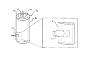
図7は、従来の基板処理室に接続されたトラップ装置の解説図である。
このトラップ装置TRは、未反応成分や残留成分等の回収成分を捕獲するフィルタ壁aと、このフィルタ壁aを収容するトラップ本体(ケーシング)bと、トラップ本体bに基板処理室内雰囲気を導入するインレット部cと、フィルタ壁aによって浄化した後の浄化ガスを排出させるアウトレット部dとを備えている。
前記フィルタ壁aは、渦巻き状に形成されていてトラップ本体b内で渦巻き状のガス経路部eを形成しており、インレット部cの出口は、ガス経路部eの上流部に連通し、アウトレット部dの導入口(図示せず)は、ガス経路部eの下流部に連通している。
また、前記ガス経路部eには、流れを遮断するための邪魔板(図示せず)が一周毎に配置されていて、この邪魔板による流れの堰きとめにより、基板処理室内雰囲気がフィルタ壁aを通過するようになっている。
前記トラップ装置TRを、基板処理装置(図示せず)のガス排気管(図示せず)に取付け、基板処理装置のガス排気管からインレット部cを通じてトラップ本体b内に基板処理室内雰囲気を導入すると、基板処理室内雰囲気は、フィルタ壁aに沿ってガス経路部e内を旋回する。そして邪魔板により一周ごとの堰きとめにより、フィルタ壁aを通過して下流部に到達する。
このように、従来のトラップ装置では、基板処理室内雰囲気がフィルタ壁aを複数回通過させることによって、基板処理室内雰囲気中の未反応成分、残留成分等の回収成分を捕集して浄化するので、清浄化されたガスがアウトレット部dから排出される。
フィルタ壁aに付着した未反応成分及び残留成分、すなわち、固形分は、所定のメンテナンス周期毎に、回収される。
FIG. 7 is an explanatory diagram of a trap apparatus connected to a conventional substrate processing chamber.
This trap device T R is introduced and the filter walls a capturing the recovered components such as unreacted components and residual components, and the trap body (casing) b for accommodating the filter wall a, a substrate processing chamber atmosphere trap body b And an outlet portion d for discharging the purified gas after being purified by the filter wall a.
The filter wall a is formed in a spiral shape and forms a spiral gas path portion e in the trap body b, and an outlet of the inlet portion c communicates with an upstream portion of the gas path portion e. An inlet (not shown) of the part d communicates with the downstream part of the gas path part e.
Further, a baffle plate (not shown) for interrupting the flow is disposed in the gas path portion e every round, and the flow of the baffle plate prevents the flow of the substrate processing chamber from the filter wall a. Is supposed to pass through.
The trap device T R, attached to a gas exhaust pipe of a substrate processing apparatus (not shown) (not shown), the substrate is treated room atmosphere through the gas exhaust pipe of the substrate processing apparatus in the trap body b through the inlet section c Then, the atmosphere in the substrate processing chamber turns in the gas path part e along the filter wall a. And it passes through the filter wall a and reaches a downstream part by damming every round by a baffle plate.
Thus, in the conventional trap apparatus, the substrate processing chamber atmosphere passes through the filter wall a a plurality of times, thereby collecting and purifying recovered components such as unreacted components and residual components in the substrate processing chamber atmosphere. The cleaned gas is discharged from the outlet part d.
Unreacted components and residual components adhering to the filter wall a, that is, solid components are collected at every predetermined maintenance cycle.
このように、従来のトラップ装置は、未反応成分、残留成分を層状の固体分としてフィルタ壁に捕獲し、所定のメンテナンス周期毎に回収するが、メンテナンス周期に到達する前に、インレット部の出口に局部的な詰りが発生してしまう場合があり、早期にメンテナンスを実施せざるを得ないことがある。
そこで、従来のトラップ装置のインレット部及びトラップ本体部内の構造と、インレット部及びトラップ本体部内での基板処理室内雰囲気の流れを検討する。
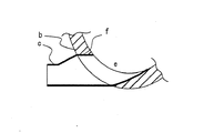
図8は従来のトラップ装置のインレット部の軸方向に沿った断面図であり、トラップ本体を破断して示した一部破断断面図である。
インレット部cとトラップ本体b内のガス経路部eとは、トラップ本体bの厚み方向に沿った直線的な連絡路fを通じて互いに連通しているが、インレット部cのトラップ本体取付部の少なくとも一がラッパ状となっていて基板処理室内雰囲気が連絡路fの内面に衝突するようになっている。
図9は、前記トラップ装置TRのインレット部c側の流れをシミュレーションによって解析した解析図である。
この図9に示すように、前記トラップ装置TRにおいては、基板処理室内雰囲気が連絡路fの内面に衝突し、連絡路f内に大きな乱れRが発生することが認められる。
従って、従来のトラップ装置においては、連絡路fの内面に基板処理室内雰囲気が衝突することによって未反応成分、残留成分が分離され、分離された未反応成分、残留成分が連絡路内の乱れ中Rに取り込まれた状態で連絡路fの内面やフィルタ壁aと衝突を繰り返すうちに付着・成長を繰り返し、詰りを発生させていたものと推定される。
そこで、トラップ部及び連絡路での基板処理室内雰囲気の流れをスムーズにするために解決すべき技術的課題が生じるのであり、本発明はこの課題を解決することを目的とする。
In this way, the conventional trap device captures unreacted components and residual components as layered solids on the filter wall and collects them every predetermined maintenance cycle, but before reaching the maintenance cycle, the outlet of the inlet section In some cases, local clogging may occur, and maintenance may have to be performed at an early stage.
Therefore, the structure in the inlet part and the trap body part of the conventional trap apparatus and the flow of the atmosphere in the substrate processing chamber in the inlet part and the trap body part are examined.
FIG. 8 is a cross-sectional view taken along the axial direction of the inlet portion of the conventional trap apparatus, and is a partially cut-away cross-sectional view showing the trap body in a broken state.
The inlet part c and the gas path part e in the trap body b communicate with each other through a linear communication path f along the thickness direction of the trap body b, but at least one of the trap body attachment parts of the inlet part c. Has a trumpet shape so that the atmosphere in the substrate processing chamber collides with the inner surface of the communication path f.
Figure 9 is an analysis diagram analyzed by simulation flow inlet portion c side of the trap device T R.
As shown in FIG. 9, in the trap device T R impinges on the inner surface of the substrate processing chamber atmosphere communicating passage f, a large disturbance R is observed to occur in the communication path f.
Therefore, in the conventional trap apparatus, the unreacted component and the remaining component are separated when the atmosphere in the substrate processing chamber collides with the inner surface of the communication path f, and the separated unreacted component and the remaining component are disturbed in the communication path. It is presumed that clogging occurred due to repeated adhesion and growth while repeatedly colliding with the inner surface of the communication path f and the filter wall a while being taken into R.
Therefore, a technical problem to be solved in order to make the flow of the atmosphere in the substrate processing chamber in the trap portion and the communication path smooth, and the present invention aims to solve this problem.
第1の手段は、基板を処理する基板処理室と、前記基板を加熱する加熱手段と、前記基板処理室に所望のガスを供給する供給系と、前記基板処理室内雰囲気を排気する排気系と、前記処理室から排気されたガスを固化して捕獲する、前記排気系に設けられたトラップ装置であって、トラップ本体と、前記トラップ本体に接続されるインレット部を含む前記トラップ装置と、を備え、前記トラップ本体は、その内部に曲率的なガス経路部を含み、前記インレット部の少なくとも一部が前記ガス経路部に基板処理室内雰囲気を滑らかに案内する曲管にて形成される基板処理システムを提供するものである。
このようにすると、トラップ本体内のガス経路部に基板処理室内雰囲気がスムーズに流れるので、乱れに起因した詰りが防止される。
The first means includes a substrate processing chamber for processing the substrate, a heating means for heating the substrate, a supply system for supplying a desired gas to the substrate processing chamber, and an exhaust system for exhausting the atmosphere in the substrate processing chamber. A trap device provided in the exhaust system for solidifying and capturing the gas exhausted from the processing chamber, the trap body including the trap body and an inlet portion connected to the trap body. The trap body includes a curved gas path portion therein, and at least a part of the inlet portion is formed by a curved pipe that smoothly guides the atmosphere in the substrate processing chamber to the gas path portion. A system is provided.
In this way, the atmosphere in the substrate processing chamber flows smoothly to the gas path portion in the trap body, so that clogging due to disturbance is prevented.
また、第2の手段は、基板処理室に連通する排気系から排気されたガスを固化して捕獲するトラップ装置であって、トラップ本体と、前記トラップ本体に接続されるインレット部を含む前記トラップ装置と、を備え、前記トラップ本体は、その内部に曲率的なガス経路部を含み、前記トラップ本体は、その内部に曲率的なガス経路部を含み、前記インレット部の少なくとも一部が前記ガス経路部に基板処理室内雰囲気を滑らかに案内する曲管にて形成される基板処理システムのトラップ装置を提供するものである。
このようにすると、第1の手段と同様に、トラップ本体内のガス経路部に基板処理室内雰囲気がスムーズに流れるので、乱れに起因した詰りが防止される。
The second means is a trap device that solidifies and traps gas exhausted from an exhaust system communicating with the substrate processing chamber, and includes the trap body and the trap portion including the inlet portion connected to the trap body. The trap body includes a curved gas path portion therein, the trap body includes a curved gas path portion therein, and at least a part of the inlet portion includes the gas. The present invention provides a trap apparatus for a substrate processing system, which is formed by a curved pipe that smoothly guides an atmosphere in a substrate processing chamber to a path portion.
In this way, as in the first means, the atmosphere in the substrate processing chamber flows smoothly through the gas path in the trap body, so that clogging due to turbulence is prevented.
なお、第1の手段及び第2の手段において、好ましくは、インレット部の曲管を、前記ガス経路部の延長線に沿わせて形成すると流れがよりスムーズなものとなる。 In the first means and the second means, preferably, if the bent pipe of the inlet portion is formed along the extension line of the gas path portion, the flow becomes smoother.
以上、要するに、本発明によれば、基板処理室内雰囲気を乱れなく又よどみなくスムーズに流すことができるのでトラップ装置の詰りを防止することができ、所定のメンテナンス周期でメンテナンスを実施することができるという優れた効果を発揮する。 As described above, according to the present invention, the atmosphere in the substrate processing chamber can be smoothly and smoothly flowed, so that the trap apparatus can be prevented from being clogged, and maintenance can be performed at a predetermined maintenance cycle. Exhibits an excellent effect.
まず、本発明の実施の形態にて行った、ウエハ等の基板へのプロセス処理例としてCVD法の中の1つであるALD法を用いた成膜処理について、簡単に説明する。 First, a film forming process using an ALD method, which is one of the CVD methods, will be briefly described as an example of a process processing on a substrate such as a wafer performed in the embodiment of the present invention.
ALD法は、ある成膜条件(温度、時間等)の下で、成膜に用いる2種類(またはそれ以上)の原料となるガスを1種類ずつ交互に基板上に供給し、1原子層単位で吸着させ、表面反応を利用して成膜を行う手法である。 In the ALD method, under one film formation condition (temperature, time, etc.), two kinds (or more) of raw material gases used for film formation are alternately supplied onto the substrate one by one, and one atomic layer unit. In this method, the film is adsorbed by using a surface reaction to form a film.
即ち、利用する化学反応には、例えばSiN(窒化珪素)膜形成の場合、ALD法では、DCS(SiH2Cl2、ジクロルシラン)とNH3(アンモニア)を用いる。これらの反応ガスは、300〜600℃の低温で高品質の成膜が可能となる。また、ガス供給は、複数種類の反応性ガスを1種類ずつ交互に供給する。そして、膜厚制御は、反応性ガス供給のサイクル数で制御する。(例えば、成膜速度が1Å/サイクルとすると、20Åの膜を形成する場合、処理を20サイクル行う。) That is, for the chemical reaction used, for example, in the case of forming a SiN (silicon nitride) film, DCS (SiH 2 Cl 2 , dichlorosilane) and NH 3 (ammonia) are used in the ALD method. These reaction gases enable high-quality film formation at a low temperature of 300 to 600 ° C. Further, the gas supply alternately supplies a plurality of types of reactive gases one by one. And film thickness control is controlled by the cycle number of reactive gas supply. (For example, assuming that the film formation rate is 1 mm / cycle, the process is performed 20 cycles when a film of 20 mm is formed.)
以下に本発明にかかる処理装置の1実施の形態を説明する。 An embodiment of a processing apparatus according to the present invention will be described below.
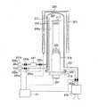
図1は本実施の形態にかかる縦型の基板処理炉の概略構成図であり、処理炉部分を縦断面で示す。図2は本実施の形態にかかる縦型の基板処理炉の概略構成図であり、処理炉部分を横断面で示す。
加熱手段であるヒータ207の内側に、基板であるウエハ200を処理する反応容器として反応管203が設けられ、この反応管203の下端開口は蓋体であるシールキャップ219により気密部材であるOリング220を介して気密に閉塞され、少なくとも、このヒータ207、反応管203、及びシールキャップ219により基板処理室である処理室201を形成している。シールキャップ219には石英キャップ218を介して基板保持手段であるボート217が立設され、前記石英キャップ218はボート217を保持する保持体となっている。そして、ボート217は処理室201に挿入される。ボート217にはバッチ処理される複数のウエハ200が水平姿勢で管軸方向に多段に積載される。前記ヒータ207は処理室201に挿入されたウエハ200を所定の温度に加熱する。
FIG. 1 is a schematic configuration diagram of a vertical substrate processing furnace according to the present embodiment, and shows a processing furnace part in a longitudinal section. FIG. 2 is a schematic configuration diagram of a vertical substrate processing furnace according to the present embodiment, and shows the processing furnace part in a cross section.
A
そして、処理室201へは複数種類、ここでは2種類のガスを供給するガス供給系としての2本のガス供給管232a、232bが設けられる。ここでは第1のガス供給管232aからは流量制御手段である第1のマスフローコントローラ241a及び開閉弁である第1のバルブ243aを介し、更に後述する処理室201内に形成されたバッファ室237を介して処理室201に反応ガスが供給され、第2のガス供給管232bからは流量制御手段である第2のマスフローコントローラ241b、開閉弁である第2のバルブ243b、ガス溜め247、及び開閉弁である第3のバルブ243cを介し、更に後述するガス供給部249を介して処理室201に反応ガスが供給されている。
The
処理室201はガスを排気するガス排気系としてのガス排気管231により第4のバルブ243dを介して排気手段である真空ポンプ246に接続され、真空排気されるようになっている。尚、この第4のバルブ243dは弁を開閉して処理室201の真空排気・真空排気停止ができ、更に弁開度を調節して圧力調整可能になっている開閉弁である。トラップ装置100(後述する)は、このガス排気管231の途中に設けられる。
The
処理室201を構成している反応管203の内壁とウエハ200との間における円弧状の空間には、反応管203の下部より上部の内壁にウエハ200の積載方向に沿って、ガス分散空間であるバッファ室237が設けられており、そのバッファ室237のウエハ200と隣接する壁の端部にはガスを供給する供給孔である第1のガス供給孔248aが設けられている。この第1のガス供給孔248aは反応管203の中心へ向けて開口している。この第1のガス供給孔248aは、下部から上部にわたってそれぞれ同一の開口面積を有し、更に同じ開口ピッチで設けられている。
The arc-shaped space between the inner wall of the
そしてバッファ室237の第1のガス供給孔248aが設けられた端部と反対側の端部には、ノズル233が、やはり反応管203の下部より上部にわたりウエハ200の積載方向に沿って配設されている。そしてノズル233には複数のガスを供給する供給孔である第2のガス供給孔248bが設けられている。この第2のガス供給孔248bの開口面積は、バッファ室237と処理室201の差圧が小さい場合には、上流側から下流側まで同一の開口面積で同一の開口ピッチとすると良いが、差圧が大きい場合には上流側から下流側に向かって開口面積を大きくするか、開口ピッチを小さくすると良い。
At the end of the
本実施の形態において、第2のガス供給孔248bの開口面積や開口ピッチを上流側から下流にかけて調節することで、まず、第2の各ガス供給孔248bよりガスの流速の差はあるが、流量はほぼ同量であるガスを噴出させる。そしてこの各第2のガス供給孔248bから噴出するガスをバッファ室237に噴出させて一旦導入し、前記ガスの流速差の均一化を行うこととした。
In the present embodiment, by adjusting the opening area and the opening pitch of the second gas supply holes 248b from the upstream side to the downstream side, first, there is a difference in gas flow velocity from each of the second
すなわち、バッファ室237において、各第2のガス供給孔248bより噴出したガスはバッファ室237で各ガスの粒子速度が緩和された後、第1のガス供給孔248aより処理室201に噴出する。この間に、各第2のガス供給孔248bより噴出したガスは、各第1のガス供給孔248aより噴出する際には、均一な流量と流速とを有するガスとすることができた。
That is, in the
さらに、バッファ室237に、細長い構造を有する第1の電極である第1の棒状電極269及び第2の電極である第2の棒状電極270が上部より下部にわたって電極を保護する保護管である電極保護管275に保護されて配設され、この第1の棒状電極269又は第2の棒状電極270のいずれか一方は整合器272を介して高周波電源273に接続され、他方は基準電位であるアースに接続されている。この結果、第1の棒状電極269及び第2の棒状電極270間のプラズマ生成領域224にプラズマが生成される。
Further, in the
前記電極保護管275は、第1の棒状電極269及び第2の棒状電極270のそれぞれをバッファ室237の雰囲気と隔離した状態でバッファ室237に挿入できる構造となっている。ここで、電極保護管275の内部は外気(大気)と同一雰囲気であると、電極保護管275にそれぞれ挿入された第1の棒状電極269及び第2の棒状電極270はヒータ207の加熱で酸化されてしまう。そこで、電極保護管275の内部は窒素などの不活性ガスを充填あるいはパージし、酸素濃度を充分低く抑えて第1の棒状電極269又は第2の棒状電極270の酸化を防止するための不活性ガスパージ機構が設けられる。
The
さらに、第1のガス供給孔248aの位置より、反応管203の内周を120°程度回った内壁に、ガス供給部249が設けられている。このガス供給部249は、ALD法による成膜においてウエハ200へ、複数種類のガスを1種類ずつ交互に供給する際に、バッファ室237とガス供給種を分担する供給部である。
Further, a
このガス供給部249もバッファ室237と同様にウエハ200と隣接する位置に同一ピッチでガスを供給する供給孔である第3のガス供給孔248cを有し、下部では第2のガス供給管232bが接続されている。
Similarly to the
第3のガス供給孔248cの開口面積はバッファ室237と処理室201との差圧が小さい場合には、上流側から下流側まで同一の開口面積で同一の開口ピッチとすると良いが、差圧が大きい場合には上流側から下流側に向かって開口面積を大きくするか開口ピッチを小さくすると良い。
When the differential pressure between the
反応管203内の中央部には複数枚のウエハ200を多段に同一間隔で載置するボート217が設けられており、このボート217は図中省略のボートエレベータ機構(図示せず)により反応管203に出入りできるようになっている。また処理の均一性を向上する為にボート217を回転するための回転手段であるボート回転機構267が設けてあり、ボート回転機構267を回転することにより、石英キャップ218に保持されたボート217を回転するようになっている。
A
制御手段であるコントローラ121は、第1、第2のマスフローコントローラ241a、241b、第1〜第4のバルブ243a、243b、243c、243d、ヒータ207、真空ポンプ246、ボート回転機構267、図中省略のボート昇降機構、高周波電源273、整合器272に接続されており、第1、第2のマスフローコントローラ241a、241bの流量調整、第1〜第3のバルブ243a、243b、243cの開閉動作、第4のバルブ243dの開閉及び圧力調整動作、ヒータ207の温度調節、真空ポンプ246の起動・停止、ボート回転機構267の回転速度調節、ボート昇降機構の昇降動作制御、高周波電源273の電力供給制御、整合器272によるインピーダンス制御が行われる。
The
次にALD法による成膜例について、DCS及びNH3ガスを用いてSiN膜を成膜する例で説明する。 Next, an example of film formation by the ALD method will be described using an example of forming an SiN film using DCS and NH 3 gas.
まず成膜しようとするウエハ200をボート217に装填し、処理室201に搬入する。搬入後、次の3つのステップを順次実行する。
First, a
[ステップ1]
ステップ1では、プラズマ励起の必要なNH3ガスと、プラズマ励起の必要のないDCSガスとを併行して流す。まず第1のガス供給管232aに設けた第1のバルブ243a、及びガス排気管231に設けた第4のバルブ243dを共に開けて、第1のガス供給管232aから第1のマスフローコントローラ241aにより流量調整されたNH3ガスをノズル233の第2のガス供給孔248bからバッファ室237へ噴出し、第1の棒状電極269及び第2の棒状電極270間に高周波電源273から整合器272を介して高周波電力を印加してNH3をプラズマ:励起し、活性種として処理室201に供給しながらガス排気管231から排気する。NH3ガスをプラズマ励起することにより活性種として流すときは、第4のバルブ243dを適正に調整して処理室201内圧力を10〜100Paとする。第1のマスフローコントローラ241aで制御するNH3の供給流量は1000〜10000sccmである。NH3をプラズマ励起することにより得られた活性種にウエハ200を晒す時間は2〜120秒間である。このときのヒータ207の温度はウエハ200が300〜600℃になるよう設定してある。NH3は反応温度が高いため、上記ウエハ温度では反応しないので、プラズマ励起することにより活性種としてから流すようにしており、このためウエハ温度は設定した低い温度範囲のままで行える。
[Step 1]
In Step 1, NH 3 gas that requires plasma excitation and DCS gas that does not require plasma excitation are caused to flow in parallel. First, the
このNH3をプラズマ励起することにより活性種として供給しているとき、第2のガス供給管232bの上流側の第2のバルブ243bを開け、下流側の第3のバルブ243cを閉めて、DCSも流すようにする。これにより第2、第3のバルブ243b、243c間に設けたガス溜め247にDCSを溜める。このとき、処理室201内に流しているガスはNH3をプラズマ励起することにより得られた活性種であり、DCSは存在しない。したがって、NH3は気相反応を起こすことはなく、プラズマにより励起され活性種となったNH3はウエハ200上の下地膜と表面反応する。
When this NH 3 is supplied as an active species by plasma excitation, the
[ステップ2]
ステップ2では、第1のガス供給管232aの第1のバルブ243aを閉めて、NH3の供給を止めるが、引続きガス溜め247へ供給を継続する。ガス溜め247に所定圧、所定量のDCSが溜まったら上流側の第2のバルブ243bも閉めて、ガス溜め247にDCSを閉じ込めておく。また、ガス排気管231の第4のバルブ243dは開いたままにし真空ポンプ246により、処理室201を20Pa以下に排気し、残留NH3を処理室201から排除する。また、この時にはN2等の不活性ガスを処理室201に供給すると、更に残留NH3を排除する効果が高まる。ガス溜め247内には、圧力が20000Pa以上になるようにDCSを溜める。また、ガス溜め247と処理室201との間のコンダクタンスが1.5×10⁻³m3/s以上になるように装置を構成する。また、反応管203の容積とこれに対する必要なガス溜め247の容積との比として考えると、反応管203の容積が100l(リットル)の場合においては、100〜300ccであることが好ましく、容積比としてはガス溜め247は反応室容積の1/1000〜3/1000倍とすることが好ましい。
[Step 2]
In Step 2, the
[ステップ3]
ステップ3では、処理室201の排気が終わったらガス排気管231の第4のバルブ243dを閉じて排気を止める。第2のガス供給管232bの下流側の第3のバルブ243cを開く。これによりガス溜め247に溜められたDCSが処理室201に一気に供給される。このときガス排気管231の第4のバルブ243dが閉じられているので、処理室201内の圧力は急激に上昇して約931Pa(7Torr)まで昇圧される。DCSを供給するための時間は2〜4秒設定し、その後上昇した圧力雰囲気中に晒す時間を2〜4秒に設定し、合計6秒とした。このときのウエハ温度はNH3の供給時と同じく、300〜600℃である。DCSの供給により、下地膜上のNH3とDCSとが表面反応して、ウエハ200上にSiN膜が成膜される。成膜後、第3のバルブ243cを閉じ、第4のバルブ243dを開けて処理室201を真空排気し、残留するDCSの成膜に寄与した後のガスを排除する。また、この時にはN2等の不活性ガスを処理室201に供給すると、更に残留するDCSの成膜に寄与した後のガスを処理室201から排除する効果が高まる。また第2のバルブ243bを開いてガス溜め247へのDCSの供給を開始する。
[Step 3]
In step 3, when the exhaust of the
上記ステップ1〜3を1サイクルとし、このサイクルを複数回繰り返すことによりウエハ200上に所定膜厚のSiN膜を成膜する。
Steps 1 to 3 are defined as one cycle, and a SiN film having a predetermined thickness is formed on the
ALD装置では、ガスは下地膜表面に吸着する。このガスの吸着量は、ガスの圧力、及びガスの暴露時間に比例する。よって、希望する一定量のガスを、短時間で吸着させるためには、ガスの圧力を短時間で大きくする必要がある。この点で、本実施の形態では、第4のバルブ243dを閉めたうえで、ガス溜め247内に溜めたDCSを瞬間的に供給しているので、処理室201内のDCSの圧力を急激に上げることができ、希望する一定量のガスを瞬間的に吸着させることができる。
In the ALD apparatus, the gas is adsorbed on the surface of the base film. The amount of gas adsorption is proportional to the gas pressure and the gas exposure time. Therefore, in order to adsorb a desired amount of gas in a short time, it is necessary to increase the gas pressure in a short time. In this regard, in the present embodiment, the DCS stored in the
また、本実施の形態では、ガス溜め247にDCSを溜めている間に、ALD法で必要なステップであるNH3ガスをプラズマ励起することにより活性種として供給、及び処理室201の排気をしているので、DCSを溜めるための特別なステップを必要としない。また、処理室201内を排気してNH3ガスを除去してからDCSを流すので、両者はウエハ200に向かう途中で反応しない。供給されたDCSは、ウエハ200に吸着しているNH3とのみ有効に反応させることができる。
Further, in the present embodiment, while DCS is stored in the
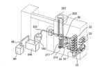
図3は被処理基板である直径300mmのウエハ200を石英製の反応管203に多段に載置してCVD処理を実施する縦型CVDシステムとして、前記処理装置(図1及び図2参照)を組み込んだ様子を示す。ウエハ200を収容したカセット32は、当該システムの前面に設置されたI/Oステージ33と装置外部との間で授受される。I/Oステージ33の内側にはカセットローダ35が設置されていて、I/Oステージ33上のカセット32をカセット棚34に搬送できるようになっている。また、カセット棚34の内側にはウエハ200をボート217に搬送するためのウエハ移載機38が配置され、カセット棚34のカセット32と石英製のボート217との間でウエハ200を搬送できるようになっている。なお、本実施形態にかかるカセット32には25枚のウエハ200を収容でき、ボート217には、100枚のウエハ200が装填できるので、ウエハ移載機38の搬送は何度か繰り返される。
前記ボート217は、ボートエレベータ36に設置され、ボートエレベータ36の昇降機構(図示せず)によるボート217の上昇によって反応管203内部に装填される。ボート217の反応管203内への挿入後は、ボート217下部のボートエレベータ36に付属する台座をかねたシールキャップ219が反応管203に気密部材であるOリング220を介して密着するので気密性が保持される。
ガス排気管231には、真空ポンプ246(図3参照)より上流側に本実施形態にかかるトラップ装置100が設けられ、下流側に、除外装置40が設けられる。
FIG. 3 shows the processing apparatus (see FIGS. 1 and 2) as a vertical CVD system for performing CVD processing by placing
The
The
前記CVDシステムで成膜処理を実施する際は、まず、ウエハ200を装填したカセット32がI/Oステージ33にセットされる。I/Oステージ33にカセット32がセットされると、カセットローダ35によってカセット32が順次、カセット棚34に搬送される。ボート217へのウエハ200の搬送が終了すると、ボートエレベータ36が作動し、ボート217の上昇によってボート217が反応管203内に挿入される。ボート217の挿入が完了すると、ボート217下部のシールキャップ219によって反応管203が閉鎖され気密性が保持される。
この状態を保持しながら反応管203内に一定流量のCVD用の反応性ガスを供給し、反応管203内の圧力を一定の圧力に保持する。このとき、反応管203及び内部のウエハ200は、前記ヒータ207によって所定温度に保持される。
反応管203内の温度を、例えば、750℃に保持し、反応管203内の圧力を、例えば、1Torrに保持しながら、前記したように、SiH2Cl2(ジクロロシラン)とNH3(アンモニア)とを交互に供給するとウエハ200の表面にSiNx膜(窒化膜)が形成される。
When performing the film forming process by the CVD system, first, the
While maintaining this state, a reactive gas for CVD at a constant flow rate is supplied into the
As described above, while maintaining the temperature in the
図4は前記トラップ装置100の構造を示す解説図である。なお、この図はトラップ装置100の上部蓋を取り外した状態を示している。
トラップ装置100は、前記反応管内雰囲気から未反応成分、残留成分等の回収成分を捕獲するフィルタ壁101と、このフィルタ壁101を収容するトラップ本体(ケーシング)102と、トラップ本体102内に前記ガス排気管231から反応管内雰囲気(基板処理室内雰囲気)を導入するためのインレット部103と、未反応成分、残留成分等の回収成分を捕獲した後の反応管内雰囲気を前記ガス排気管231に排気するためのアウトレット部104とで構成される。
前記トラップ本体102は、両端部が閉塞された円筒状に形成されていて、フィルタ壁101はトラップ本体102に内蔵されている。
前記フィルタ壁101は、図4には詳細に示されていないが、フィルタで構成されており、渦巻き状に成形された後に、トラップ本体102に内蔵される。
渦巻き状のフィルタ壁101が前記トラップ本体102内に内蔵されると、トラップ本体102内には、渦巻き状のガス経路部105が形成される。
なお、図4には示していないが、ガス経路部105には、一周毎に邪魔板が配置されていて、邪魔板がガスの流れを一周毎に遮断するようになっている。基板処理室内雰囲気がフィルタ壁101を通過すると、未反応成分、残留成分がフィルタ壁101に捕獲される。
前記ガス経路部105に、基板処理室内雰囲気を導入するためのインレット部103は、トラップ本体102に溶接により気密に取付けられており、図5(a)に示すように、トラップ本体102を厚み方向に貫通する連絡路106を通じてガス経路部105の上流部に連通している。
アウトレット部104はガス経路部105の下流部に連通しており、トラップ本体102の端部壁を内側から外側に貫通して外部に所定長さ延びている。
FIG. 4 is an explanatory view showing the structure of the
The
The
Although not shown in detail in FIG. 4, the
When the
Although not shown in FIG. 4, a baffle plate is arranged in the
An
The
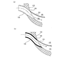
図5(a)、(b)はインレット部103、連絡路106及びガス経路部105の軸方向に沿った断面図である。図5(a)に示されるように、前記連絡路106はガス経路部105の延長線に沿った曲線的な貫通孔となっており、インレット部103は、溶接により、トラップ本体102の外面に気密に取付けられている。また、このインレット部103は、トラップ本体102に対する取付け側が湾曲した曲管となっていて、連絡路106に吸入される基板処理室内雰囲気が乱れを起こすことのないように連絡路106に対して基板処理室雰囲気を滑らかに案内する曲管となっている。ここで、「滑らかに案内する」という表現には、流れの断面に突起物や凹凸がなく、流体の剥離に起因した乱流を発生させないという形態も含まれるものとする。
図5(b)は、インレット部103の曲管をガス経路部105側に延ばし連絡路106内に挿入した一例を示している。このように、インレット部103の曲管の延出部を連絡路106に内に挿入し、インレット部103の延出部によって連絡路106の内面を覆うと、インレット部103と連絡路106、連絡路106とガス経路部105との接続に継目がなくなるので、継目による乱流の発生も抑制される。この場合、前記インレット部103の延出部を更に延ばしてその先端部をガス経路部105の上流部に挿入してもよい。このようにすると、インレット部103、連絡路106、ガス経路部105の上流部が経路部105の下流部に対して反応室内雰囲気を乱れなく滑らかに案内する一本の管路を構成するので、ガス経路部105内に乱れが生じることなく基板処理室内雰囲気を吸入させることができる。
5A and 5B are cross-sectional views along the axial direction of the
FIG. 5B shows an example in which the curved pipe of the
図6は前記真空ポンプ246によって反応管内雰囲気(基板処理室内雰囲気)を吸引したときのインレット部103及びガス経路部105の流れの状態をシミュレーションによって解析した解析図である。
この解析図に示されるように、インレット部103の少なくともトラップ本体側取付部、連絡路106を曲管としてこれらをガス経路部105の一部として含ませると、インレット部103、連絡路106及びガス経路部105の反応管内雰囲気の流れが上流側から下流側に及んでスムーズになり、乱れやよどみが発生することがない。
FIG. 6 is an analysis diagram analyzing the flow state of the
As shown in the analysis diagram, when at least the trap body side attachment portion of the
図3に示すように、本実施形態にかかるトラップ装置100を前記システムのガス排気管231に組み込み、前記ウエハ200の成膜を繰り返しても反応管内雰囲気中(基板処理室内雰囲気中)の未反応成分、残留成分等の回収成分がインレット部103の内面、連絡路106の内面、及びフィルタ壁101の上流部に、局部的に付着することはなく、フィルタ壁101の上流側から下流側に及んで略均一に且つ層状に付着することが確認された。なお、本実施の形態では、付着物としては、不活性ガスによって反応管203から排気されたNH3の未反応分(残留分)と、反応管203から排気されたDCS(SiH2Cl2、ジクロルシラン)の未反応分(残留分)とが該当する。
従って、本実施形態のトラップ装置100によれば詰りが防止され、所定のメンテナンス周期でのメンテナンスが可能となる。
トラップ装置100によって浄化した後の反応室内雰囲気は、図3に示すように、真空ポンプ246を通過し、ガス排気管231の集合部45を経て除外装置40に導入され、ここで、最終の浄化処理を受けて清浄な排気として大気に開放される。
As shown in FIG. 3, the
Therefore, according to the
As shown in FIG. 3, the atmosphere in the reaction chamber after purification by the
なお、本実施形態では、インレット部103の曲管、連絡路106の曲率は、ガス経路部105に滑らかに接続され、結果的に詰りが生じない限りはどのような曲率であっても構わないが、ガス経路部105の延長線方向に沿ったものとする方が流れがスムーズになる。
In this embodiment, the curvature of the bent pipe of the
また、トラップ装置100は、真空ポンプ246と除外装置との間に設置してもよい。
The
なお、本実施形態においては、縦型のCVD処理装置を組み込んだシステムを例示したが、横型の処理装置や枚葉式の処理装置を組んだシステムとしてもよい。
さらに、本発明にかかるトラップ装置100は、排気ガスから微粒子状の成分を捕獲して浄化する他の処理装置への適用が可能である。
このように、本発明は、種々の改変が可能であり、この改変された及ぶことは当然である。
In the present embodiment, a system incorporating a vertical CVD processing apparatus is illustrated, but a system incorporating a horizontal processing apparatus or a single wafer processing apparatus may be used.
Furthermore, the
As described above, the present invention can be modified in various ways, and it is natural that the modified scope extends.
100 トラップ装置
101 フィルタ壁
102 トラップ本体
103 インレット部
105 ガス経路部
106 連絡路
DESCRIPTION OF
Claims (2)
前記基板を加熱する加熱手段と、
前記基板処理室に所望のガスを供給する供給系と、
前記基板処理室内雰囲気を排気する排気系と、
前記処理室から排気されたガスを固化して捕獲する、前記排気系に設けられたトラップ装置であって、トラップ本体と、前記トラップ本体に接続されるインレット部を含む前記トラップ装置と、を備え、
前記トラップ本体は、前記トラップ本体を厚み方向に貫通し、前記インレット部が接続される連絡路と、前記連絡路と接続される渦巻き状のガス経路部とを有し、
前記連絡路は、前記ガス経路部の延長線に沿った曲線的な貫通孔であり、
前記インレット部の少なくとも一部が前記連絡路に基板処理室内雰囲気を滑らかに案内する曲管にて形成されることを特徴とする基板処理システム。 A substrate processing chamber for processing the substrate;
Heating means for heating the substrate;
A supply system for supplying a desired gas to the substrate processing chamber;
An exhaust system for exhausting the atmosphere in the substrate processing chamber;
A trap device provided in the exhaust system that solidifies and captures gas exhausted from the processing chamber, the trap device including a trap body and an inlet portion connected to the trap body. ,
The trap body passes through the trap body in the thickness direction, and has a communication path to which the inlet part is connected, and a spiral gas path part connected to the communication path,
The communication path is a curved through hole along an extension line of the gas path part,
At least a part of the inlet portion is formed by a curved pipe that smoothly guides the atmosphere in the substrate processing chamber to the communication path .
トラップ本体と、前記トラップ本体に接続されるインレット部を含む前記トラップ装置と、を備え、
前記トラップ本体は、その内部に渦巻き状のガス経路部と、前記ガス経路部の延長線に沿った曲線的な貫通孔とを含み、前記インレット部は、前記貫通孔に接続され、前記インレット部の少なくとも一部が前記連絡路に基板処理室内雰囲気を滑らかに案内する曲管にて形成されることを特徴とする基板処理システムのトラップ装置。 A trap device that solidifies and captures gas exhausted from an exhaust system communicating with a substrate processing chamber,
A trap body, and the trap device including an inlet portion connected to the trap body,
The trap body includes a spiral gas path portion therein and a curved through hole along an extension line of the gas path portion, and the inlet portion is connected to the through hole, and the inlet portion A trap apparatus for a substrate processing system, wherein at least a part of the trap is formed by a curved pipe that smoothly guides the atmosphere in the substrate processing chamber to the communication path .
Priority Applications (1)
| Application Number | Priority Date | Filing Date | Title |
|---|---|---|---|
| JP2005210713A JP4580833B2 (en) | 2005-07-21 | 2005-07-21 | Substrate processing system and trap apparatus |
Applications Claiming Priority (1)
| Application Number | Priority Date | Filing Date | Title |
|---|---|---|---|
| JP2005210713A JP4580833B2 (en) | 2005-07-21 | 2005-07-21 | Substrate processing system and trap apparatus |
Publications (2)
| Publication Number | Publication Date |
|---|---|
| JP2007027590A JP2007027590A (en) | 2007-02-01 |
| JP4580833B2 true JP4580833B2 (en) | 2010-11-17 |
Family
ID=37787920
Family Applications (1)
| Application Number | Title | Priority Date | Filing Date |
|---|---|---|---|
| JP2005210713A Active JP4580833B2 (en) | 2005-07-21 | 2005-07-21 | Substrate processing system and trap apparatus |
Country Status (1)
| Country | Link |
|---|---|
| JP (1) | JP4580833B2 (en) |
Cited By (1)
| Publication number | Priority date | Publication date | Assignee | Title |
|---|---|---|---|---|
| JP2007039751A (en) * | 2005-08-03 | 2007-02-15 | Hitachi Kokusai Electric Inc | Substrates processing system and its trapping mechanism |
Families Citing this family (2)
| Publication number | Priority date | Publication date | Assignee | Title |
|---|---|---|---|---|
| JP5303864B2 (en) | 2007-05-21 | 2013-10-02 | 信越化学工業株式会社 | Curable fluoropolyether composition and integrally molded product of cured rubber and organic resin using the same |
| WO2013187734A1 (en) * | 2012-06-15 | 2013-12-19 | Ku Bon Su | Apparatus for manufacturing contact tip for welding torch by forging |
Citations (5)
| Publication number | Priority date | Publication date | Assignee | Title |
|---|---|---|---|---|
| JPH04311030A (en) * | 1991-04-09 | 1992-11-02 | Fuji Electric Co Ltd | Vapor deposition device |
| JPH10150032A (en) * | 1996-10-30 | 1998-06-02 | Applied Materials Inc | Microwave device for in-situ cleaning for vacuum pipe of substrate processor |
| JP2000353668A (en) * | 1999-06-14 | 2000-12-19 | Seiko Epson Corp | Vapor-phase content removing device |
| JP2001059159A (en) * | 1999-08-20 | 2001-03-06 | Ishikawajima Harima Heavy Ind Co Ltd | Vacuum evaporation equipment |
| JP2005052786A (en) * | 2003-08-07 | 2005-03-03 | Japan Pionics Co Ltd | Treating apparatus of exhaust gas |
-
2005
- 2005-07-21 JP JP2005210713A patent/JP4580833B2/en active Active
Patent Citations (5)
| Publication number | Priority date | Publication date | Assignee | Title |
|---|---|---|---|---|
| JPH04311030A (en) * | 1991-04-09 | 1992-11-02 | Fuji Electric Co Ltd | Vapor deposition device |
| JPH10150032A (en) * | 1996-10-30 | 1998-06-02 | Applied Materials Inc | Microwave device for in-situ cleaning for vacuum pipe of substrate processor |
| JP2000353668A (en) * | 1999-06-14 | 2000-12-19 | Seiko Epson Corp | Vapor-phase content removing device |
| JP2001059159A (en) * | 1999-08-20 | 2001-03-06 | Ishikawajima Harima Heavy Ind Co Ltd | Vacuum evaporation equipment |
| JP2005052786A (en) * | 2003-08-07 | 2005-03-03 | Japan Pionics Co Ltd | Treating apparatus of exhaust gas |
Cited By (1)
| Publication number | Priority date | Publication date | Assignee | Title |
|---|---|---|---|---|
| JP2007039751A (en) * | 2005-08-03 | 2007-02-15 | Hitachi Kokusai Electric Inc | Substrates processing system and its trapping mechanism |
Also Published As
| Publication number | Publication date |
|---|---|
| JP2007027590A (en) | 2007-02-01 |
Similar Documents
| Publication | Publication Date | Title |
|---|---|---|
| JP5253589B2 (en) | Semiconductor device manufacturing method and substrate processing apparatus | |
| KR100707819B1 (en) | Substrate processing device | |
| KR101195410B1 (en) | Semiconductor device manufacturing method and substrate processing apparatus | |
| JP3403181B2 (en) | Heat treatment apparatus and heat treatment method | |
| JP5568212B2 (en) | Substrate processing apparatus, coating method therefor, substrate processing method, and semiconductor device manufacturing method | |
| JP4410211B2 (en) | Film forming apparatus and film forming method | |
| JP2006303414A (en) | Substrate processing system | |
| JP4580833B2 (en) | Substrate processing system and trap apparatus | |
| JP4717495B2 (en) | Substrate processing system | |
| JP4242733B2 (en) | Manufacturing method of semiconductor device | |
| JP2011187536A (en) | Substrate processing device | |
| JP4938805B2 (en) | Substrate processing equipment | |
| JP2007039751A (en) | Substrates processing system and its trapping mechanism | |
| JP4434807B2 (en) | Manufacturing method of semiconductor device | |
| JP2007042897A (en) | Substrate processing system | |
| JP4267434B2 (en) | Substrate processing equipment | |
| JP2011035191A (en) | Substrate treatment device | |
| JP2005223144A (en) | Substrate-processing apparatus | |
| JP4509697B2 (en) | Substrate processing equipment | |
| JP2005243737A (en) | Substrate processing apparatus | |
| JP2005167027A (en) | Substrate processing apparatus | |
| JP2011134748A (en) | Method of manufacturing semiconductor device | |
| JP2007027425A (en) | Substrate treatment device | |
| JP2006216612A (en) | Substrate-treating device | |
| JP2006295032A (en) | Substrate processing equipment |
Legal Events
| Date | Code | Title | Description |
|---|---|---|---|
| A621 | Written request for application examination |
Free format text: JAPANESE INTERMEDIATE CODE: A621 Effective date: 20071225 |
|
| A977 | Report on retrieval |
Free format text: JAPANESE INTERMEDIATE CODE: A971007 Effective date: 20100611 |
|
| A131 | Notification of reasons for refusal |
Free format text: JAPANESE INTERMEDIATE CODE: A131 Effective date: 20100615 |
|
| A521 | Request for written amendment filed |
Free format text: JAPANESE INTERMEDIATE CODE: A523 Effective date: 20100730 |
|
| TRDD | Decision of grant or rejection written | ||
| A01 | Written decision to grant a patent or to grant a registration (utility model) |
Free format text: JAPANESE INTERMEDIATE CODE: A01 Effective date: 20100818 |
|
| A01 | Written decision to grant a patent or to grant a registration (utility model) |
Free format text: JAPANESE INTERMEDIATE CODE: A01 |
|
| A61 | First payment of annual fees (during grant procedure) |
Free format text: JAPANESE INTERMEDIATE CODE: A61 Effective date: 20100830 |
|
| FPAY | Renewal fee payment (event date is renewal date of database) |
Free format text: PAYMENT UNTIL: 20130903 Year of fee payment: 3 |
|
| R150 | Certificate of patent or registration of utility model |
Ref document number: 4580833 Country of ref document: JP Free format text: JAPANESE INTERMEDIATE CODE: R150 Free format text: JAPANESE INTERMEDIATE CODE: R150 |
|
| R250 | Receipt of annual fees |
Free format text: JAPANESE INTERMEDIATE CODE: R250 |
|
| R250 | Receipt of annual fees |
Free format text: JAPANESE INTERMEDIATE CODE: R250 |
|
| R250 | Receipt of annual fees |
Free format text: JAPANESE INTERMEDIATE CODE: R250 |
|
| R250 | Receipt of annual fees |
Free format text: JAPANESE INTERMEDIATE CODE: R250 |
|
| R250 | Receipt of annual fees |
Free format text: JAPANESE INTERMEDIATE CODE: R250 |
|
| R250 | Receipt of annual fees |
Free format text: JAPANESE INTERMEDIATE CODE: R250 |
|
| S111 | Request for change of ownership or part of ownership |
Free format text: JAPANESE INTERMEDIATE CODE: R313115 |
|
| S531 | Written request for registration of change of domicile |
Free format text: JAPANESE INTERMEDIATE CODE: R313531 |
|
| R350 | Written notification of registration of transfer |
Free format text: JAPANESE INTERMEDIATE CODE: R350 |
|
| R250 | Receipt of annual fees |
Free format text: JAPANESE INTERMEDIATE CODE: R250 |
|
| R250 | Receipt of annual fees |
Free format text: JAPANESE INTERMEDIATE CODE: R250 |
|
| R250 | Receipt of annual fees |
Free format text: JAPANESE INTERMEDIATE CODE: R250 |
|
| R250 | Receipt of annual fees |
Free format text: JAPANESE INTERMEDIATE CODE: R250 |
|
| R250 | Receipt of annual fees |
Free format text: JAPANESE INTERMEDIATE CODE: R250 |
|
| R250 | Receipt of annual fees |
Free format text: JAPANESE INTERMEDIATE CODE: R250 |
