KR20180089625A - LiDAR scanning device - Google Patents
LiDAR scanning device Download PDFInfo
- Publication number
- KR20180089625A KR20180089625A KR1020170014209A KR20170014209A KR20180089625A KR 20180089625 A KR20180089625 A KR 20180089625A KR 1020170014209 A KR1020170014209 A KR 1020170014209A KR 20170014209 A KR20170014209 A KR 20170014209A KR 20180089625 A KR20180089625 A KR 20180089625A
- Authority
- KR
- South Korea
- Prior art keywords
- mirror
- laser beam
- transmission
- receiving
- reception
- Prior art date
Links
Images
Classifications
-
- G—PHYSICS
- G01—MEASURING; TESTING
- G01S—RADIO DIRECTION-FINDING; RADIO NAVIGATION; DETERMINING DISTANCE OR VELOCITY BY USE OF RADIO WAVES; LOCATING OR PRESENCE-DETECTING BY USE OF THE REFLECTION OR RERADIATION OF RADIO WAVES; ANALOGOUS ARRANGEMENTS USING OTHER WAVES
- G01S7/00—Details of systems according to groups G01S13/00, G01S15/00, G01S17/00
- G01S7/48—Details of systems according to groups G01S13/00, G01S15/00, G01S17/00 of systems according to group G01S17/00
- G01S7/481—Constructional features, e.g. arrangements of optical elements
- G01S7/4816—Constructional features, e.g. arrangements of optical elements of receivers alone
-
- G—PHYSICS
- G01—MEASURING; TESTING
- G01S—RADIO DIRECTION-FINDING; RADIO NAVIGATION; DETERMINING DISTANCE OR VELOCITY BY USE OF RADIO WAVES; LOCATING OR PRESENCE-DETECTING BY USE OF THE REFLECTION OR RERADIATION OF RADIO WAVES; ANALOGOUS ARRANGEMENTS USING OTHER WAVES
- G01S7/00—Details of systems according to groups G01S13/00, G01S15/00, G01S17/00
- G01S7/48—Details of systems according to groups G01S13/00, G01S15/00, G01S17/00 of systems according to group G01S17/00
- G01S7/481—Constructional features, e.g. arrangements of optical elements
- G01S7/4814—Constructional features, e.g. arrangements of optical elements of transmitters alone
-
- G—PHYSICS
- G01—MEASURING; TESTING
- G01S—RADIO DIRECTION-FINDING; RADIO NAVIGATION; DETERMINING DISTANCE OR VELOCITY BY USE OF RADIO WAVES; LOCATING OR PRESENCE-DETECTING BY USE OF THE REFLECTION OR RERADIATION OF RADIO WAVES; ANALOGOUS ARRANGEMENTS USING OTHER WAVES
- G01S7/00—Details of systems according to groups G01S13/00, G01S15/00, G01S17/00
- G01S7/48—Details of systems according to groups G01S13/00, G01S15/00, G01S17/00 of systems according to group G01S17/00
- G01S7/481—Constructional features, e.g. arrangements of optical elements
- G01S7/4817—Constructional features, e.g. arrangements of optical elements relating to scanning
-
- G—PHYSICS
- G02—OPTICS
- G02B—OPTICAL ELEMENTS, SYSTEMS OR APPARATUS
- G02B7/00—Mountings, adjusting means, or light-tight connections, for optical elements
- G02B7/18—Mountings, adjusting means, or light-tight connections, for optical elements for prisms; for mirrors
- G02B7/182—Mountings, adjusting means, or light-tight connections, for optical elements for prisms; for mirrors for mirrors
- G02B7/1821—Mountings, adjusting means, or light-tight connections, for optical elements for prisms; for mirrors for mirrors for rotating or oscillating mirrors
Landscapes
- Engineering & Computer Science (AREA)
- Physics & Mathematics (AREA)
- General Physics & Mathematics (AREA)
- Computer Networks & Wireless Communication (AREA)
- Radar, Positioning & Navigation (AREA)
- Remote Sensing (AREA)
- Optics & Photonics (AREA)
- Optical Radar Systems And Details Thereof (AREA)
Abstract
Description
본 발명은 레이저 빔를 대상체에 조사하여 대상체에 의해 반사되어 돌아오는 레이저 빔을 분석해서 대상체까지의 거리, 방향, 속도 등을 측정하는 라이다 스캐닝 장치에 관한 것이다. BACKGROUND OF THE
일반적으로, 라이다 시스템(LIDAR system; Light Detection And Ranging system)은 레이저를 대상체에 조사하고, 대상체에 의해 반사되어 돌아오는 레이저 빔을 분석해서 대상체까지의 거리, 방향, 속도 등을 측정 감지할 수 있는 시스템이다.In general, the LIDAR system (Light Detection and Ranging system) irradiates a laser to a target object, analyzes the laser beam reflected by the target object, and measures the distance, direction, and speed to the target object System.
이러한 라이다 시스템은 기상 관측이나, 거리 측정 등의 용도를 위해 활용되다가, 최근에는 자율 주행 차량, 위성을 이용한 기상 관측, 무인 로봇 센서 및 3차원 영상 모델링을 위한 기술 등에 사용되고 있다. These Lidar systems are used for weather observation and distance measurement. Recently, they have been used for autonomous vehicles, meteorological observations using satellites, unmanned robot sensors, and technologies for 3D image modeling.
레이저 빔은 측정방법에 따라 사인파, 펄스파 등으로 조사될 수 있고, 2D 맵핑이나 3D 형상 측정시 레이저 빔의 측정점을 옮기기 위해서는 모터나 미러 등으로 구성된 라이다 스캐닝 장치가 필요하다. The laser beam can be irradiated with a sinusoidal wave or pulsed wave according to the measurement method. In order to move the measurement point of the laser beam in the 2D mapping or 3D shape measurement, a Lada scanning device composed of a motor or a mirror is required.
라이다 스캐닝 장치는 송신빔과 수신빔 간의 배열 방식에 따라 co-axial 방식, bi-axial 방식 등이 있다.The Rada scanning apparatus has a co-axial system and a bi-axial system depending on the arrangement between the transmission beam and the reception beam.
도 1은 송신빔과 수신빔간 배열 방식에 따른 라이다 스캐닝 장치가 도시된 도면이다.FIG. 1 is a diagram illustrating a linear scanning apparatus according to a transmission beam and a reception beam arraying scheme. Referring to FIG.
도 1에 도시된 바와 같이, co-axial 방식의 라이다 스캐닝 장치는 송신빔과 수신빔의 축이 일치하도록 배열되고, bi-axial 방식의 라이다 스캐닝 장치는 송신빔과 수신빔의 축이 일치하지 않고 평행하도록 배열된다.1, a co-axial type Ridas scanning device is arranged such that the axes of a transmission beam and a reception beam coincide with each other, and a bi-axial type Radid scanning device is arranged such that axes of a transmission beam and a reception beam coincide with each other But arranged in parallel.
co-axial 방식은 송신부의 일부가 수광빔을 가리는 구조이나, bi-axial은 가리지 않는 구조이다. 측정 거리면에서 bi-axial이 유리하나, bi-axial 방식은 근거리 측정일수록 집광 위치가 변해서 측정이 안될 수 있는 단점이 있다.In the co-axial method, a part of the transmitting part covers the light-receiving beam, but the bi-axial is not selected. The bi-axial method is advantageous at the measurement distance, but the bi-axial method has a disadvantage in that measurement at the near-field measurement can not be performed due to the change of the condensing position.
도 3 내지 도 5는 종래 기술에 따른 라이다 스캐닝 장치가 도시된 도면이다.FIGS. 3 to 5 are diagrams illustrating a conventional Lada scanning apparatus.
도 3은 SICK사의 대표적인 스캐닝 방식을 도시하고 있다. 도 3의 스캐닝 방식은 단일 송신부와 단일 수신부로 이루어지며, 송신빔과 수신빔간 배열은 co-axial 방식이다. 하나의 단면 미러 사용하며, 미러의 회전축이 송신부 및 수신부 축과 일치하는 것이 특징이다.FIG. 3 shows a typical scanning method of the SICK company. The scanning method of FIG. 3 includes a single transmitting unit and a single receiving unit, and the arrangement between the transmitting beam and the receiving beam is co-axial. One end face mirror is used, and the rotation axis of the mirror coincides with the transmission part and the reception part axis.
도 3의 스캐닝 방식은 송신부가 집광렌즈로 들어오는 수신빔의 일부를 가리므로 수광 측면에서 손실이 발생하고, 이에 따라 최대 측정 거리가 짧아지게 되는 문제점이 있다.In the scanning method of FIG. 3, since the transmitting part covers a part of the receiving beam entering the condensing lens, loss occurs on the light receiving side, which results in a shortest maximum measuring distance.
도 4는 Hokuyo 사의 대표적인 스캐닝 방식이다. 도 4의 스캐닝 방식은 단일 송신부와 단일 수신부로 이루어지며, 송신빔과 수신빔간 배열은 bi-axial 방식이다. dual shaft 모터를 사용하여 두 개의 미러를 동시에 회전시키며, 미러의 회전축은 송신부 및 수신부 축과 일치하는 것이 특징이다.4 is a representative scanning method of Hokuyo. The scanning method of FIG. 4 includes a single transmitting unit and a single receiving unit, and the arrangement between the transmitting beam and the receiving beam is bi-axial. A dual shaft motor is used to rotate two mirrors at the same time, and the rotation axis of the mirror coincides with the transmission and reception axes.
도 4의 스캐닝 방식은 특수모터를 사용해야 하고, 단면 미러를 사용하므로 고속 스캐닝에 불리하며 3D 측정이 어렵다는 문제점이 있다.The scanning method of FIG. 4 requires a special motor and uses a single-sided mirror, which is disadvantageous for high-speed scanning and has a problem that 3D measurement is difficult.
본 발명은 상기한 종래의 스캐닝 방식의 문제점을 해결할 수 있는 라이다 스캐닝 장치를 제공하는 것을 목적으로 한다.SUMMARY OF THE INVENTION It is an object of the present invention to provide a Lada scanning apparatus capable of solving the problems of the conventional scanning method.
본 발명의 실시예에 따른 라이다 스캐닝 장치는,A ladder scanning apparatus according to an embodiment of the present invention includes:
레이저 빔을 조사하는 송신부; 상기 송신부로부터 조사되는 레이저 빔을 반사시키는 반사 미러; 상기 반사 미러로부터 반사된 레이저 빔을 전방위로 방사시키며, 다각뿔 형상으로 형성되며 각 면의 기울기가 상이한 송신 미러; 상기 송신 미러에서 방사된 후, 대상체에서 반사된 레이저 빔을 수신하며, 각 면의 곡률이 상이한 다면으로 형성된 수신 미러; 상기 수신 미러에서 반사된 레이저 빔을 수신하는 수신부; 상기 송신 미러와 수신 미러를 회전시키는 회전 모터;를 포함한다.A transmitter for irradiating a laser beam; A reflection mirror for reflecting the laser beam irradiated from the transmission unit; A transmission mirror which radiates the laser beam reflected from the reflection mirror in all directions and which is formed in a polygonal pyramid shape and has different slopes of respective surfaces; A receiving mirror for receiving the laser beam reflected from the object after being radiated from the transmitting mirror, the receiving mirror being formed so that curvatures of the respective surfaces are different; A receiving unit for receiving the laser beam reflected by the receiving mirror; And a rotation motor for rotating the transmission mirror and the reception mirror.
본 발명의 일 양상에 의하면, 상기 수신 미러의 각 면은, 상기 송신 미러의 각 면이 하방향으로 연장되어 형성된 것을 특징으로 한다.According to one aspect of the present invention, each surface of the reception mirror is formed such that each surface of the transmission mirror extends downward.
본 발명의 일 양상에 의하면, 상기 수신부는 상기 반사 미러 상부에 이격되어 형성된 것을 특징으로 한다.According to an aspect of the present invention, the receiving unit is formed to be spaced apart from the reflection mirror.
본 발명의 일 양상에 의하면, 상기 송신부와 상기 수신부는 상기 송신 미러의 위치를 기준으로 상측의 동일한 공간에 형성된 것을 특징으로 한다.According to an aspect of the present invention, the transmitting unit and the receiving unit are formed in the same space on the upper side with reference to the position of the transmitting mirror.
본 발명의 일 양상에 의하면, 상기 송신 미러와 이격되어 형성되며, 일 방향이 개방된 링 형상으로 형성된 빔 차단부를 포함하는 것을 특징으로 한다.According to an aspect of the present invention, there is provided a beam splitter formed apart from the transmission mirror and formed in a ring shape having one opening.
기타 본 발명의 다양한 측면에 따른 구현예들의 구체적인 사항은 이하의 상세한 설명에 포함되어 있다.Other specific embodiments of various aspects of the present invention are included in the detailed description below.
본 발명의 실시 형태에 따른 라이다 스캐닝 장치는, A ladder scanning apparatus according to an embodiment of the present invention includes:
bi-axial 방식으로 구성되어, 송신부가 수신빔의 일부를 가리지 않으므로 수광 측면에서 손실이 발생하지 않는 효과가 있다.since the transmission part does not cover a part of the reception beam, there is an effect that no loss occurs on the light receiving side.
또한, dual shaft 모터와 같은 특수모터를 사용하지 않고, 면마다 측정 고도가 다른 다면 미러로 구성되어, 고속 스캐닝 및 3D 측정이 가능한 효과가 있다.In addition, it does not use a special motor such as a dual shaft motor, and it is composed of mirrors with different measurement altiments for each surface, which enables high-speed scanning and 3D measurement.
또한, 반사 미러와 수신부의 축은 회전 모터의 회전축을 연장한 가상의 회전축과 일치하도록 형성함으로써, 모든 방위각에 대하여 대상체에서 반사된 레이저 빔(수신빔)은 수신부에 집광될 수 있게 되고, 이에 따라, 수신부가 단일채널로 구성된 경우에도 3D 측정이 가능해지는 효과가 있다. The reflection mirror and the axis of the receiving section are formed so as to coincide with a virtual rotation axis extending the rotation axis of the rotation motor. Thus, the laser beam (reception beam) reflected by the object with respect to all the azimuth angles can be focused on the reception section, There is an effect that 3D measurement can be performed even when the receiving unit is constituted by a single channel.
도 1은 송신빔과 수신빔간 배열 방식에 따른 라이다 스캐닝 장치가 도시된 도면이다.
도 2는 SICK사의 대표적인 라이다 스캐닝 장치가 도시된 단면도이고, 도 3은 도 2의 사시도이다.
도 4는 Hokuyo사의 대표적인 라이다 스캐닝 장치가 도시된 단면도이고, 도 5은 도 4의 사시도이다.
도 6은 본 발명의 일 실시예에 따른 라이다 스캐닝 장치가 도시된 사시도이다.
도 7은 본 발명의 일 실시예에 따른 라이다 스캐닝 장치가 도시된 단면도이다.
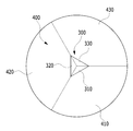
도 8은 송신 미러 및 수신 미러가 도시된 평면도이다.
도 9는 송신 미러에서 방사된 레이저 빔 방향이 예시된 평면도이다.
도 10은 송신 미러 및 수신 미러가 도시된 사시도이다.
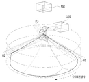
도 11은 송신 미러에서 방사된 레이저 빔 방향이 예시된 사시도이다.
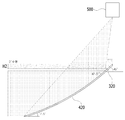
도 12 내지 도 14는 송신 미러에서 방사된 레이저 빔이 다른 측정고도로 방사되는 것을 예시하는 도면이다.
도 15는 수신 미러 주변에 형성된 빔 차단부가 도시된 평면도이다.
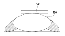
도 16은 수신 미러 주변에 형성된 빔 차단부가 도시된 측면도이다.
도 17은 빔 차단부가 형성된 라이다 스캐닝 장치의 동작 상태가 도시된 도면이다.
도 18은 송신 미러 및 수신 미러가 하나의 면으로 구성된 경우의 라이다 스캐닝 장치가 도시된 단면도이다.
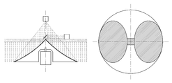
도 19는 송신 미러 및 수신 미러가 2개의 면으로 구성된 경우의 라이다 스캐닝 장치가 도시된 단면도이다.
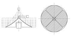
도 20은 송신 미러 및 수신 미러가 4개의 면으로 구성된 경우의 라이다 스캐닝 장치가 도시된 단면도이다.FIG. 1 is a diagram illustrating a linear scanning apparatus according to a transmission beam and a reception beam arraying scheme. Referring to FIG.
FIG. 2 is a cross-sectional view showing a typical Raidas scanning apparatus of SICK, and FIG. 3 is a perspective view of FIG. 2. FIG.
FIG. 4 is a cross-sectional view showing a typical Raidas scanning apparatus of Hokuyo Company, and FIG. 5 is a perspective view of FIG.
6 is a perspective view illustrating a Lada scanning apparatus according to an exemplary embodiment of the present invention.
7 is a cross-sectional view illustrating a Lada scanning apparatus according to an exemplary embodiment of the present invention.
8 is a plan view showing a transmission mirror and a reception mirror.
9 is a plan view illustrating the laser beam direction emitted from the transmission mirror.
10 is a perspective view showing a transmission mirror and a reception mirror.
11 is a perspective view illustrating the laser beam direction emitted from the transmission mirror.
Figs. 12-14 illustrate how a laser beam emitted from a transmission mirror is radiated at different measurement heights. Fig.
15 is a plan view showing a beam shielding portion formed around the reception mirror;
16 is a side view showing a beam shielding portion formed around the reception mirror;
17 is a diagram showing an operation state of the Lada scanning device formed with the beam shielding part.
18 is a cross-sectional view showing a ladder scanning apparatus in a case where the transmission mirror and the reception mirror are constituted by one plane.
FIG. 19 is a cross-sectional view showing a Lada scanning device in the case where the transmission mirror and the reception mirror are constituted by two planes.
20 is a cross-sectional view showing a Lada scanning device in a case where the transmission mirror and the reception mirror are composed of four planes.
본 발명은 다양한 변환을 가할 수 있고 여러 가지 실시예를 가질 수 있는 바, 특정 실시예를 예시하고 상세한 설명에 상세하게 설명하고자 한다. 그러나, 이는 본 발명을 특정한 실시 형태에 대해 한정하려는 것이 아니며, 본 발명의 사상 및 기술 범위에 포함되는 모든 변환, 균등물 내지 대체물을 포함하는 것으로 이해되어야 한다.The present invention is capable of various modifications and various embodiments and is intended to illustrate and describe the specific embodiments in detail. It is to be understood, however, that the invention is not to be limited to the specific embodiments, but includes all modifications, equivalents, and alternatives falling within the spirit and scope of the invention.
본 발명에서 사용한 용어는 단지 특정한 실시예를 설명하기 위해 사용된 것으로, 본 발명을 한정하려는 의도가 아니다. 단수의 표현은 문맥상 명백하게 다르게 뜻하지 않는 한, 복수의 표현을 포함한다. 본 발명에서, '포함하다' 또는 '가지다' 등의 용어는 명세서상에 기재된 특징, 숫자, 단계, 동작, 구성요소, 부품 또는 이들을 조합한 것이 존재함을 지정하려는 것이지, 하나 또는 그 이상의 다른 특징들이나 숫자, 단계, 동작, 구성요소, 부품 또는 이들을 조합한 것들의 존재 또는 부가 가능성을 미리 배제하지 않는 것으로 이해되어야 한다. 이하, 도면을 참조하여 본 발명의 실시예에 따른 라이다 스캐닝 장치를 설명한다.The terminology used herein is for the purpose of describing particular embodiments only and is not intended to be limiting of the invention. The singular expressions include plural expressions unless the context clearly dictates otherwise. In the present invention, terms such as "comprises" or "having" are used to designate the presence of stated features, integers, steps, operations, elements, components, or combinations thereof, But do not preclude the presence or addition of one or more other features, integers, steps, operations, elements, components, or combinations thereof. Hereinafter, a Ridas scanning apparatus according to an embodiment of the present invention will be described with reference to the drawings.
도 6은 본 발명의 일 실시예에 따른 라이다 스캐닝 장치가 도시된 사시도이고, 도 7은 본 발명의 일 실시예에 따른 라이다 스캐닝 장치가 도시된 단면도이다.FIG. 6 is a perspective view illustrating a Lada scanning apparatus according to an exemplary embodiment of the present invention, and FIG. 7 is a cross-sectional view illustrating a Lada scanning apparatus according to an exemplary embodiment of the present invention.
도 6 및 도 7에 도시된 바와 같이, 본 발명의 일 실시예에 따른 라이다 스캐닝 장치는, 송신부(100), 반사 미러(200), 송신 미러(300), 수신 미러(400), 수신부(500), 회전 모터(600)를 포함한다.6 and 7, a ladder scanning apparatus according to an embodiment of the present invention includes a transmitting
송신부(100)는 반사 미러(200)와 수평 방향으로 일정 거리 이격되어 형성되며, 반사 미러(200)에 레이저 빔을 조사한다. 송신부(100)는, 예를 들어 레이저 다이오드(LD)가 사용될 수 있으며, 단일로 이루어질 수 있다.The transmitting
반사 미러(200)는 레이저 빔을 조사하는 송신부(100)와 일정 거리 이격 형서되며, 송신부(100)로부터 조사되는 레이저 빔을 송신 미러(300) 방향으로 반사시킨다. The
송신 미러(300)는 반사 미러(200) 하부에 일정 거리 이격 형성되며, 반사 미러(200)로부터 반사된 레이저 빔(송신빔)을 전방위로 방사시킨다. The
도 8 및 도 9에 도시된 바와 같이, 송신 미러(300)는 다각뿔 형상으로 형성되며, 다각뿔의 옆면을 형성하는 각 면(310, 320, 330)은 각각 다른 기울기로 형성된다. 송신 미러(300)의 각 면(310, 320, 330)들이 각각 다른 기울기로 형성됨으로써, 반사 미러(200)로부터 입사하는 레이저 빔은 각각 다른 기울기의 면에서 반사되어 각각 다른 고도로 방사된다.As shown in FIGS. 8 and 9, the
즉, 도 11에 도시된 바와 같이, 송신 미러(300)의 제1면(310)에서 반사된 레이저 빔은 제1면(310)의 기울기에 의해 제1 측정고도(H1)로 방사되고, 제2면(320)에서 반사된 레이저 빔은 제2면(320)의 기울기에 의해 제2 측정고도(H2)로 방사되고, 제3면(330)에서 반사된 레이저 빔은 제3면(330)의 기울기에 의해 제3 측정고도(H3)로 방사된다. 11, the laser beam reflected from the
수신 미러(400)는 송신 미러(300)에서 방사된 후, 대상체에서 반사된 레이저 빔을 수신한다. 수신 미러(400)는 다각뿔대 형상으로 형성되며, 다각뿔대의 옆면을 형성하는 각 면(410, 420, 430)은 각각 다른 곡률을 가진 곡선 기울기로 형성된다.The
수신 미러(400)의 각 면(410, 420, 430)은 송신 미러(300)를 이루는 다각뿔 형상의 각 면이 하방향으로 연장되어 형성된다. 따라서, 수신 미러(400)의 면 수는 송신 미러(300)의 면수와 동일한 면수로 이루어질 수 있으며, 제조시에 송신 미러(300)와 수신 미러(400)가 일체로 형성되어 다각뿔 형상으로 형성될 수 있다. 물론, 이에 한정되지 않고, 수신 미러(400)의 면 수는 송신 미러(300)의 면 수와 다르게 형성될 수도 있다.Each of the
도 10에 도시된 바와 같이,송신 미러(300) 부분의 각 면은 직선 기울기(G1)를 갖도록 형성되고, 수신 미러(400) 부분의 각 면은 각각 다른 곡률을 가진 곡선 기울기(G2)를 갖도록 형성되어, 각 면마다 측정고도가 다르므로 입체적인 3D 측정이 가능하다.10, each surface of the transmitting
송신 미러(300)에서 방사된 레이저 빔이 다른 측정고도(H1, H2, H3)로 방사되는 것과 관련하여 도 12 내지 도 14를 참조하여 보다 상세히 설명한다.The laser beam emitted from the
도 12는 송신 미러(300)의 제1면(310)에서 반사된 레이저 빔의 방향이 도시되어 있다. 제1면(310)는 수평선을 기준으로 47.5도의 기울기로 형성되며, 제1면(310)에서 반사된 레이저 빔은 수평선을 기준으로 5도 하강하여 제1 측정고도(H1)로 방사된다. 이때, 수신 미러(400) 제1면(410)의 상측은 수평선을 기준으로 45도의 기울기로 형성될 수 있으며, 하측은 수평선을 기준으로 20도의 기울기로 형성될 수 있다. 상측과 하측 사이의 곡면은 기설정된 제1 곡률로 곡선 기울기를 이룬다.12 shows the direction of the laser beam reflected by the
도 13은 송신 미러(300)의 제2면(320)에서 반사된 레이저 빔의 방향이 도시되어 있다. 제2면(320)는 수평선을 기준으로 45도의 기울기로 형성되며, 제2면(320)에서 반사된 레이저 빔은 수평선과 나란한 방향인 제2 측정고도(H2)로 방사된다. 이때, 수신 미러(400) 제2면(420)의 상측은 수평선을 기준으로 42.5도의 기울기로 형성될 수 있으며, 하측은 수평선을 기준으로 17.5도의 기울기로 형성될 수 있다. 상측과 하측 사이의 곡면은 기설정된 제2 곡률로 곡선 기울기를 이룬다.13 shows the direction of the laser beam reflected from the
도 14는 송신 미러(300)의 제3면(330)에서 반사된 레이저 빔의 방향이 도시되어 있다. 제3면(330)는 수평선을 기준으로 42.5도의 기울기로 형성되며, 제3면(330)에서 반사된 레이저 빔은 수평선을 기준으로 5도 상승하여 제3 측정고도(H3)로 방사된다. 이때, 수신 미러(400) 제3면(430)의 상측은 수평선을 기준으로 42.5도의 기울기로 형성될 수 있으며, 하측은 수평선을 기준으로 15도의 기울기로 형성될 수 있다. 상측과 하측 사이의 곡면은 기설정된 제3 곡률로 곡선 기울기를 이룬다.14 shows the direction of the laser beam reflected by the
수신부(500)는 수신 미러(400)에서 반사된 레이저 빔을 수신하며, 레이저빔을 수광하는 이미지센서(미도시)를 포함할 수 있다. 수신부(500)는 반사 미러(200) 상부에 일정 거리 이격되어 형성된다. 송신부(100)와 수신부(500)는 송신 미러(300)와 수신 미러(400)의 위치를 기준으로 상측의 동일한 공간에 형성된다.The receiving
수신 미러(400)는 소정 곡률을 가진 곡면으로 형성되므로, 수신 미러(400)로 입사되는 레이저 빔은 곡면에 의해 반사되면서 동시에 집광되어 수신부(500)에 의해 수광된다. 따라서, 본 발명의 수신부(500)는 별도로 집광렌즈를 구비할 필요가 없어서, 구조가 간소화되고 제조 단가를 절감할 수 있게 된다.Since the receiving
한편, 수신부(500)는 수신 픽셀이 하나의 세트로 구성되어 단일 방향에서 입사되는 레이저 빔을 수신하는 단일채널 수신부 또는 수신 픽셀이 복수의 세트로 구성되어 복수의 방향에서 입사되는 레이저 빔을 구별하여 수신하는 다채널 수신부일 수 있다. Meanwhile, the receiving
단일채널 수신부인 경우, 여러 방위각에서 동시에 입사하는 레이저 빔을 구별할 수 없는 반면, 그만큼 제조 비용을 절감할 수 있다.In the case of a single-channel receiving unit, it is not possible to distinguish the incident laser beams at various azimuth angles simultaneously, but the manufacturing cost can be reduced accordingly.
다채널 수신부인 경우, 여러 방위각에서 동시에 입사하는 레이저 빔을 구별할 수 있지만, 그만큼 제조 비용을 상승하는 문제가 있다.In the case of a multi-channel receiving section, it is possible to distinguish laser beams entering at various azimuth angles at the same time, but the manufacturing cost increases accordingly.
회전 모터(600)는 수신 미러(400) 내부 공간에 형성된다. 수신 미러(400), 송신 미러(300)는 회전 모터(600)의 회전축(610)에 의해 동축 회전하고, 송신 미러(300) 상부에 이격 형성된 반사 미러(200)와 수신부(500)의 축은 회전 모터(600)의 회전축(610)을 연장한 가상의 회전축과 일치하도록 형성된다.The
이에 따라, 모든 방위각에 대하여 대상체에서 반사된 레이저 빔(수신빔)은 수신부(500)에 집광될 수 있다. 또한, 이에 따라, 수신부(500)가 단일채널로 구성된 경우에도 3D 측정이 가능해진다. 한편, 다채널 수신부를 사용하면 단일채널 수신부 사용시보다 신속하게 전방위(360도) 3D 측정이 가능하다.Accordingly, the laser beam (receiving beam) reflected by the object with respect to all the azimuth angles can be converged on the receiving
한편, 수신부(500)가 단일채널로 구성된 경우, 여러 방위각에서 동시에 입사하는 레이저 빔을 구별할 수 없으므로, 정확한 측정을 하기 어렵게 된다. On the other hand, when the receiving
이에 본 발명에서는, 도 15 및 도 16에 도시된 바와 같이, 수신부(500)가 단일채널로 구성된 경우라도 정확한 측정이 가능해지도록 한 방향의 레이저 빔을 제외한 나머지 레이저 빔의 경로를 차단하는 빔 차단부(700)를 더 포함할 수 있다.In the present invention, as shown in FIG. 15 and FIG. 16, a beam blocking unit for blocking the path of the remaining laser beam except for one directional laser beam so that accurate measurement can be performed even when the receiving
빔 차단부(700)는 송신 미러(300) 주위에 송신 미러(300)와 이격되어 형성되며, 일 방향이 개방된 링 형상으로 형성된다. 도 15에서는 좌측이 개방된 원형링 형상의 빔 차단부(700)가 예시되어 있으나, 링 형상은 원형에 한정되지 않고, 타원 또는 각형 링일 수 있고, 개방된 방향도 우측 또는 상측 또는 하측 또는 대각 방향일 수 있다.The
송신 미러(300) 주위에 빔 차단부(700)가 형성된 경우, 반사 미러(200)에서 반사된 레이저 빔은 송신 미러(300)에서 전방위로 방사되나, 빔 차단부(700)에 의해 어느 한 방향의 레이저 빔만 송신된다. 어느 한 방향으로 송신된 레이저 빔은 대상체에서 반사되어 수신 미러(400)를 통해 수신부(500)로 입사된다. When the
이때, 수신 미러(400)에 의해 수신부(500)로 입사되는 레이저 빔도 하나이므로, 단일채널 수신부라도 그 방향을 구별할 수 있으므로 정확한 측정이 가능하다. 또한, 송신 미러(300)가 회전 모터(600)에 의해 회전되므로, 일 방향으로만 송신되는 레이저 빔이라도 송신 미러(300)의 각 면(310, 320, 330)에 의해 방사되므로 다양한 측정고도로 방사될 수 있고, 수신 미러(400)의 각 면(410, 420, 430)에 의해 수신되므로, 3D 측정이 가능해진다.At this time, since there is also one laser beam incident on the receiving
상기의 설명에서 송신 미러(300) 및 수신 미러(400)의 면 수는 3개인 경우를 예로 설명하였으나, 송신 미러(300) 및 수신 미러(400)의 면 수는 이에 한정되지 않고 다양하게 설정될 수 있다.The number of the transmission mirrors 300 and the reception mirrors 400 is three, but the number of the transmission mirrors 300 and the reception mirrors 400 is not limited to this, .
예를 들어, 도 18에 도시된 바와 같이, 송신 미러(300) 및 수신 미러(400)가 하나의 면으로 구성될 수 있다. 이 경우, 회전 모터(600)의 회전에 의해 송신 미러(300) 및 수신 미러(400)가 있는 쪽이 편심되어 회전축(610)의 내구성에 악영향을 줄 수 있으므로, 송신 미러(300) 및 수신 미러(400)가 있는 쪽의 반대편에 무게 보상부(800)를 형성하여 회전축(610)이 편심되지 않도록 하는 것이 바람직하다.For example, as shown in FIG. 18, the
도 18의 경우, 송신 미러(300) 및 수신 미러(400)의 면 수가 하나이므로, 다양한 측정고도를 측정할 수는 없으나, 동일 평면 상의 전방위 물체에 대해 감지할 수 있다.In the case of FIG. 18, since the number of surfaces of the
도 19는 송신 미러(300) 및 수신 미러(400)의 면 수가 2개인 경우이고, 도 20은 송신 미러(300) 및 수신 미러(400)의 면 수가 4개인 경우이다.FIG. 19 shows a case where the number of sides of the
다음으로, 상기와 같이 구성되는 본 발명의 실시예에 따른 라이다 스캐닝 장치의 동작 과정을 설명한다.Next, the operation of the LIDAR scanning device according to the embodiment of the present invention will be described.
송신부(100)로부터 반사 미러(200) 방향으로 레이저 빔이 조사되면, 반사 미러(200)는 입사되는 레이저 빔을 반사시켜서 송신 미러(300)로 입사되도록 한다. When the laser beam is radiated from the
송신 미러(300)는 반사 미러(200)에서 반사된 레이저 빔을 전방위로 방사시킨다. 이때, 송신 미러(300)는 회전 모터(600)에 의해 회전되고, 송신 미러(300)의 각 면은 각각 다른 직선 기울기를 가지므로, 여러 측정고도로 레이저 빔을 방사시킬 수 있다. 한편, 수신부(500)가 단일채널인 경우, 송신 미러(300) 주위에는 빔 차단부(700)가 형성되고, 빔 차단부(700)에 의해 어느 한 방향으로만 레이저 빔이 방사된다.The
방사된 레이저 빔은 대상체에서 반사되어 수신 미러(400)로 입사된다. 이때, 수신 미러(400)는 회전 모터(600)에 의해 회전되고, 수신 미러(400)의 각 면은 곡면으로 형성되어, 수신 미러(400)에 의해 반사된 레이저 빔은 수신부(500)로 집광된다. 이때, 수신 미러(400)의 각 면은 각각 다른 곡선 기울기를 가지므로, 여러 측정고도에서 입사되는 레이저 빔을 반사시켜서 수신부(500)로 집광시킬 수 있다.The emitted laser beam is reflected by the object and is incident on the receiving
이상, 본 발명의 일 실시예에 대하여 설명하였으나, 해당 기술 분야에서 통상의 지식을 가진 자라면 특허청구범위에 기재된 본 발명의 사상으로부터 벗어나지 않는 범위 내에서, 구성 요소의 부가, 변경, 삭제 또는 추가 등에 의해 본 발명을 다양하게 수정 및 변경시킬 수 있을 것이며, 이 또한 본 발명의 권리범위 내에 포함된다고 할 것이다.It will be apparent to those skilled in the art that various modifications and variations can be made in the present invention without departing from the spirit of the invention as set forth in the appended claims. The present invention can be variously modified and changed by those skilled in the art, and it is also within the scope of the present invention.
100 : 송신부
200 : 반사 미러
300 : 송신 미러
400 : 수신 미러
500 : 수신부
600 : 회전 모터
700 : 빔 차단부
800 : 무게 보상부100: transmission unit 200: reflection mirror
300: transmission mirror 400: reception mirror
500: Receiving unit 600: Rotary motor
700: beam blocking part 800: weight compensating part
Claims (5)
상기 송신부로부터 조사되는 레이저 빔을 반사시키는 반사 미러;
상기 반사 미러로부터 반사된 레이저 빔을 전방위로 방사시키며, 다각뿔 형상으로 형성되며 각 면의 기울기가 상이한 송신 미러;
상기 송신 미러에서 방사된 후, 대상체에서 반사된 레이저 빔을 수신하며, 각 면의 곡률이 상이한 다면으로 형성된 수신 미러;
상기 수신 미러에서 반사된 레이저 빔을 수신하는 수신부;
상기 송신 미러와 수신 미러를 회전시키는 회전 모터;
를 포함하는 라이다 스캐닝 장치.
A transmitter for irradiating a laser beam;
A reflection mirror for reflecting the laser beam irradiated from the transmission unit;
A transmission mirror which radiates the laser beam reflected from the reflection mirror in all directions and which is formed in a polygonal pyramid shape and has different slopes of respective surfaces;
A receiving mirror for receiving the laser beam reflected from the object after being radiated from the transmitting mirror, the receiving mirror being formed so that curvatures of the respective surfaces are different;
A receiving unit for receiving the laser beam reflected by the receiving mirror;
A rotation motor for rotating the transmission mirror and the reception mirror;
And a scanning unit.
상기 수신 미러의 각 면은, 상기 송신 미러의 각 면이 하방향으로 연장되어 형성된 것을 특징으로 하는 라이다 스캐닝 장치.
The method according to claim 1,
Wherein each surface of the reception mirror is formed so that each surface of the transmission mirror extends downward.
상기 수신부는 상기 반사 미러 상부에 이격되어 형성된 것을 특징으로 하는 라이다 스캐닝 장치.
The method according to claim 1,
And the receiving unit is spaced apart from the reflecting mirror.
상기 송신부와 상기 수신부는 상기 송신 미러의 위치를 기준으로 상측의 동일한 공간에 형성된 것을 특징으로 하는 라이다 스캐닝 장치.
The method according to claim 1,
Wherein the transmitting unit and the receiving unit are formed in the same space on the upper side with respect to the position of the transmission mirror.
상기 송신 미러와 이격되어 형성되며, 일 방향이 개방된 링 형상으로 형성된 빔 차단부를 포함하는 것을 특징으로 하는 라이다 스캐닝 장치.The method according to claim 1,
And a beam blocking part formed in a ring shape and spaced apart from the transmission mirror and opened in one direction.
Priority Applications (1)
| Application Number | Priority Date | Filing Date | Title |
|---|---|---|---|
| KR1020170014209A KR101918683B1 (en) | 2017-02-01 | 2017-02-01 | LiDAR scanning device |
Applications Claiming Priority (1)
| Application Number | Priority Date | Filing Date | Title |
|---|---|---|---|
| KR1020170014209A KR101918683B1 (en) | 2017-02-01 | 2017-02-01 | LiDAR scanning device |
Publications (2)
| Publication Number | Publication Date |
|---|---|
| KR20180089625A true KR20180089625A (en) | 2018-08-09 |
| KR101918683B1 KR101918683B1 (en) | 2019-02-08 |
Family
ID=63251294
Family Applications (1)
| Application Number | Title | Priority Date | Filing Date |
|---|---|---|---|
| KR1020170014209A KR101918683B1 (en) | 2017-02-01 | 2017-02-01 | LiDAR scanning device |
Country Status (1)
| Country | Link |
|---|---|
| KR (1) | KR101918683B1 (en) |
Cited By (4)
| Publication number | Priority date | Publication date | Assignee | Title |
|---|---|---|---|---|
| WO2020092058A1 (en) * | 2018-11-01 | 2020-05-07 | Waymo Llc | Lidar with tilted and offset optical cavity |
| KR20200131491A (en) * | 2019-05-14 | 2020-11-24 | 현대모비스 주식회사 | Lidar apparatus |
| KR20210025777A (en) * | 2019-08-28 | 2021-03-10 | (주)카네비컴 | Lidar device and operation method thereof |
| EP3792653A1 (en) * | 2019-09-12 | 2021-03-17 | Riegl Laser Measurement Systems GmbH | Laser scanner |
Citations (1)
| Publication number | Priority date | Publication date | Assignee | Title |
|---|---|---|---|---|
| KR101687994B1 (en) | 2016-04-29 | 2016-12-20 | (주) 위키옵틱스 | LIDAR light-emitting system |
Family Cites Families (4)
| Publication number | Priority date | Publication date | Assignee | Title |
|---|---|---|---|---|
| JP3810045B2 (en) * | 1998-12-01 | 2006-08-16 | 本田技研工業株式会社 | Radar equipment |
| JP5402772B2 (en) * | 2010-03-25 | 2014-01-29 | 株式会社日本自動車部品総合研究所 | Optical radar device |
| JP5729358B2 (en) * | 2011-09-22 | 2015-06-03 | 株式会社リコー | Optical beam scanner and laser radar unit |
| JP6123163B2 (en) * | 2012-03-21 | 2017-05-10 | 株式会社豊田中央研究所 | Distance measuring device |
-
2017
- 2017-02-01 KR KR1020170014209A patent/KR101918683B1/en active IP Right Grant
Patent Citations (1)
| Publication number | Priority date | Publication date | Assignee | Title |
|---|---|---|---|---|
| KR101687994B1 (en) | 2016-04-29 | 2016-12-20 | (주) 위키옵틱스 | LIDAR light-emitting system |
Cited By (6)
| Publication number | Priority date | Publication date | Assignee | Title |
|---|---|---|---|---|
| WO2020092058A1 (en) * | 2018-11-01 | 2020-05-07 | Waymo Llc | Lidar with tilted and offset optical cavity |
| US11662465B2 (en) | 2018-11-01 | 2023-05-30 | Waymo Llc | LIDAR with tilted and offset optical cavity |
| KR20200131491A (en) * | 2019-05-14 | 2020-11-24 | 현대모비스 주식회사 | Lidar apparatus |
| KR20210025777A (en) * | 2019-08-28 | 2021-03-10 | (주)카네비컴 | Lidar device and operation method thereof |
| EP3792653A1 (en) * | 2019-09-12 | 2021-03-17 | Riegl Laser Measurement Systems GmbH | Laser scanner |
| WO2021047846A1 (en) * | 2019-09-12 | 2021-03-18 | Riegl Laser Measurement Systems Gmbh | Laser scanner |
Also Published As
| Publication number | Publication date |
|---|---|
| KR101918683B1 (en) | 2019-02-08 |
Similar Documents
| Publication | Publication Date | Title |
|---|---|---|
| US11774557B2 (en) | Distance measurement instrument with scanning function | |
| US20210215825A1 (en) | Distance detection device | |
| JP2021131539A (en) | Sensor system and method thereof | |
| US10788574B2 (en) | LIDAR device and LIDAR system including the same | |
| KR101785253B1 (en) | LIDAR Apparatus | |
| KR101918683B1 (en) | LiDAR scanning device | |
| US10073165B2 (en) | Distance measurement instrument with scanning function | |
| US10775485B2 (en) | LIDAR device and system comprising the same | |
| CN210142187U (en) | Distance detection device | |
| US11662463B2 (en) | Lidar apparatus and method | |
| KR20160113794A (en) | Omnidirectional LIDAR Apparatus | |
| KR102350621B1 (en) | Lidar apparatus | |
| US11237255B2 (en) | LiDAR system | |
| KR102350613B1 (en) | Irrotational omnidirectional lidar apparatus | |
| CN110531369A (en) | A kind of solid-state laser radar | |
| CN111263898A (en) | Light beam scanning system, distance detection device and electronic equipment | |
| KR102178376B1 (en) | Omnidirectional rotationless scanning lidar system | |
| US20210025986A1 (en) | Scanning device and measuring device | |
| US20220082665A1 (en) | Ranging apparatus and method for controlling scanning field of view thereof | |
| JP2023020552A (en) | Surveying device | |
| JP2017125765A (en) | Object detection device | |
| US11372109B1 (en) | Lidar with non-circular spatial filtering | |
| CN117355765A (en) | Detection method and device | |
| WO2022040937A1 (en) | Laser scanning device and laser scanning system | |
| CN111684305A (en) | Ranging system and mobile platform |
Legal Events
| Date | Code | Title | Description |
|---|---|---|---|
| A201 | Request for examination | ||
| E902 | Notification of reason for refusal | ||
| AMND | Amendment | ||
| E601 | Decision to refuse application | ||
| AMND | Amendment | ||
| X701 | Decision to grant (after re-examination) | ||
| GRNT | Written decision to grant |


