JP2016176285A - Remote control type drain plug device - Google Patents

Remote control type drain plug device Download PDF

Info

Publication number
JP2016176285A
JP2016176285A JP2015058500A JP2015058500A JP2016176285A JP 2016176285 A JP2016176285 A JP 2016176285A JP 2015058500 A JP2015058500 A JP 2015058500A JP 2015058500 A JP2015058500 A JP 2015058500A JP 2016176285 A JP2016176285 A JP 2016176285A
Authority
JP
Japan
Prior art keywords
operated
reciprocating
valve member
drain
plug device
Prior art date
Legal status (The legal status is an assumption and is not a legal conclusion. Google has not performed a legal analysis and makes no representation as to the accuracy of the status listed.)
Pending
Application number
JP2015058500A
Other languages
Japanese (ja)
Inventor
木村 裕史
Yasushi Kimura
裕史 木村
平井 良典
Yoshinori Hirai
良典 平井
Current Assignee (The listed assignees may be inaccurate. Google has not performed a legal analysis and makes no representation or warranty as to the accuracy of the list.)
Maruichi Corp
Original Assignee
Maruichi Corp
Priority date (The priority date is an assumption and is not a legal conclusion. Google has not performed a legal analysis and makes no representation as to the accuracy of the date listed.)
Filing date
Publication date
Application filed by Maruichi Corp filed Critical Maruichi Corp
Priority to JP2015058500A priority Critical patent/JP2016176285A/en
Publication of JP2016176285A publication Critical patent/JP2016176285A/en
Pending legal-status Critical Current

Links

Images

Landscapes

  • Sink And Installation For Waste Water (AREA)

Abstract

PROBLEM TO BE SOLVED: To provide a remote control type drain plug device capable of easily changing the direction of operation added to an operation body of an operation part without a burden to a release wire even in a narrow space.SOLUTION: A remote control type drain plug device is composed of a drain port, a valve member 2 for opening-closing the drain port, an operation part 3 having an operation body 4 for operating opening-closing of the drain port and a release wire 11 for transmitting operation added to the operation body 4 to the valve member 2, and comprises an output body 5 for reciprocating on a straight line in the optional direction different from a straight line for reciprocating this operation body 4 by setting the operation of the operation body 4 as operation for reciprocating on an optional straight line, and is constituted so as to open-close the drain port by operating the valve member 2 by transmitting operation of the output body 5 to the side end part of the operation part 3 of an inner wire 11b, by setting the reciprocating direction of the end part of the inner wire 11b of the release wire 11 in the same as the reciprocating direction of the output body 5, by converting reciprocating operation to the operation body 4 into reciprocating operation to the output body 5, by using a rack tooth 7 and a gear 6.SELECTED DRAWING: Figure 2

Description

本発明は、遠隔操作式排水栓装置に関し、更に詳しくは、排水口を開閉する操作を行う遠隔操作式排水栓装置の操作部の改良構造に関するものである。   The present invention relates to a remote-operated drain plug device, and more particularly to an improved structure of an operation unit of a remote-operated drain plug device that performs an operation of opening and closing a drain port.

従来より、浴槽や洗面ボウルなどの槽体の内部に生じた排水を処理するため、槽体の底面等に排水口を設け、この排水口から配管部材を介し、下水側に排水を排出する方法が広く知られている。また、槽体内に水を溜める場合に、弁部材を利用して排水口を開閉する方法があるが、この弁部材による排水口の開閉を、弁部材自体や排水口から離間した位置、例えば槽体周縁の壁面に設けた操作部への操作によって行う遠隔操作式排水栓装置が知られている。
以下に、特許文献1に記載された、従来の遠隔操作式排水栓装置水栓装置を説明する。
特許文献1に記載の遠隔操作式排水栓装置は、以下に記載する槽体である洗面ボウルを備えた洗面台に施工される排水配管であって、以下に記載する、排水口本体、弁部材、継手部材、操作部、レリースワイヤ、排水管、等の部材から構成される。
洗面台は、以下に記載する、槽体である洗面ボウルと、該洗面ボウルを載架するキャビネット部と、から構成される。
洗面ボウルは、上方が開口した箱体形状を成す槽体であって、その底面に、後述する排水口本体を取り付ける取付口を備えてなる。
また、槽体部分の後方の上端部分から、上方に向かって垂立する壁面であるバックガード部を備えてなり、更に該バックガード部上に、操作部を取り付ける為の操作部取付口を備えてなる。
キャビネット部は、上記洗面ボウルを載架する箱体であって、上面は開放されて洗面ボウルを載架するように構成されてなる。
排水口本体は、略円筒形状の部材であって、その内部に排水口を形成し、施工完了時上縁部分が洗面ボウルの取付口に接続固定される。
弁部材は、略円盤状の弁体と、該弁体の下面中央から垂下された弁軸部と、から構成され、該弁部材が降下して排水口上縁近傍を覆うことで排水口を閉塞する。
継手部材は、管体を略L字形状に屈曲させた部材であって、その内部にインナーワイヤの動作に対応して、弁軸を押し上げた状態で支持する支持部を備えてなると共に、水平方向を向いた管体部分の上方にレリースワイヤの接続部を備えてなる。施工完了時、上流側端部は排水口部材の下流側端部に、下流側端部は排水管に、それぞれ接続される。
操作部は、バックガード部の操作部取付口に取り付けられる部材であって、以下に記載する操作体と、操作部本体と、から構成される。
操作体は、遠隔操作式排水栓装置の使用者が把持して押し引きの操作を行うツマミ部と、ツマミ部にネジによって接続される直線状の軸部と、から構成されてなる。尚、軸部は、施工時においては、後述するレリースワイヤのインナーワイヤ端部に一体の部材となるようにして接続固定されてなる。
操作部本体は、略円筒形状にして一方の端部に鍔部を備えて構成してなり、その内部に進退自在に操作体の軸部を収納する。またその後端には、レリースワイヤのアウターチューブの操作部側端部が接続固定される。また、操作部本体の雄ネジと螺合する雌ネジを備えた板ナット部材を備えてなる。
レリースワイヤは、操作体に加えられた操作を、弁部材側に伝達するための部材であって、筒状にして軸方向に剛性を、側面方向に可撓性を備えたアウターチューブと、上記アウターチューブ内を摺動自在に動作する、軸方向に剛性を、側面方向に可撓性を備えたインナーワイヤと、から構成される。
また、施工時において、インナーワイヤの操作部側の端部に、インナーワイヤと一体の部材となるようにして操作体の軸部が接続固定されてなる。
排水管は、継手部材の下流側端部と床下配管とを接続する管体であって、その途中部分に管体をS字形状に屈曲させたトラップ部を備えてなる。
Conventionally, in order to treat drainage generated inside a tank body such as a bathtub or wash bowl, a drain outlet is provided on the bottom surface of the tank body, and the drainage is discharged from the drain port to the sewage side through a piping member. Is widely known. In addition, when water is accumulated in the tank body, there is a method of opening and closing the drainage port using a valve member. However, the valve member can be opened and closed at a position separated from the valve member itself or the drainage port, for example, a tank. There is known a remote-operated drain plug device that is operated by operating an operation unit provided on a wall surface of the body periphery.
Below, the conventional remote-operated drain plug device faucet device described in Patent Document 1 will be described.
The remote-operated drain plug device described in Patent Document 1 is a drain pipe constructed on a wash basin provided with a wash bowl, which is a tank body described below, and includes a drain outlet body and a valve member described below. , A joint member, an operation unit, a release wire, a drain pipe, and the like.
The washstand is composed of a wash bowl, which is a tank body, described below, and a cabinet section on which the wash bowl is placed.
The wash bowl is a tank body having a box shape with an upper opening, and includes a mounting opening for attaching a drain outlet main body, which will be described later, to the bottom surface.
In addition, it includes a back guard portion that is a wall surface that hangs upward from the upper end portion at the rear of the tank body portion, and further includes an operation portion attachment port for attaching the operation portion on the back guard portion. It becomes.
A cabinet part is a box which mounts the said wash bowl, Comprising: The upper surface is open | released and it is comprised so that a wash bowl may be mounted.
The drain port body is a substantially cylindrical member, and forms a drain port therein, and the upper edge portion is connected and fixed to the mounting port of the wash bowl when construction is completed.
The valve member is composed of a substantially disc-shaped valve body and a valve shaft portion suspended from the center of the lower surface of the valve body. The valve member descends to cover the vicinity of the upper edge of the drain port, thereby closing the drain port. To do.
The joint member is a member obtained by bending the tubular body into a substantially L-shape, and includes a support portion that supports the valve shaft in a state where the valve shaft is pushed up in response to the operation of the inner wire. A release wire connecting portion is provided above the tube portion facing in the direction. When the construction is completed, the upstream end is connected to the downstream end of the drain port member, and the downstream end is connected to the drain pipe.
An operation part is a member attached to the operation part attachment port of a back guard part, Comprising: The operation body described below and an operation part main body are comprised.
The operating body is composed of a knob portion that is held and pushed and pulled by a user of the remote-operated drain plug device, and a linear shaft portion that is connected to the knob portion with a screw. In addition, the shaft portion is connected and fixed so as to be an integral member at an inner wire end portion of a later-described release wire at the time of construction.
The operation portion main body has a substantially cylindrical shape and is provided with a collar portion at one end portion, and accommodates the shaft portion of the operation body so as to freely advance and retract. Moreover, the operation part side edge part of the outer tube of a release wire is connected and fixed to the rear end. Moreover, the plate nut member provided with the internal thread screwed with the external thread of the operation part main body is provided.
The release wire is a member for transmitting the operation applied to the operation body to the valve member side, and is a cylindrical outer tube having rigidity in the axial direction and flexibility in the side surface, An inner wire that is slidably moved in the outer tube and has rigidity in the axial direction and flexibility in the side surface direction.
Further, at the time of construction, the shaft portion of the operation body is connected and fixed to the end portion of the inner wire on the operation portion side so as to become a member integral with the inner wire.
The drainage pipe is a pipe body that connects the downstream end of the joint member and the underfloor pipe, and includes a trap part that is bent in an S-shape in the middle part thereof.

上記のように構成した従来例の遠隔操作式排水栓装置は、以下のようにして、槽体である洗面ボウルを備えた洗面台に施工される。
まず、事前に、洗面ボウルをキャビネット部上に載置し洗面台とした上で、洗面台を施工場所に設置する。
次に、洗面ボウルの取付口に排水口本体を、バックガード部の操作部取付口に操作部本体を、それぞれ接続固定する。更に、レリースワイヤの操作部側端部を操作部本体に接続し、インナーワイヤの端部に備えられた軸部が、操作部本体内部を進退自在な状態とした上で、アウターチューブ端部が、操作部本体に接続固定された状態とする。
次に、レリースワイヤの排水口側の端部を、継手部材の接続部に接続する。
次に、継手部材の上流側端部を排水口本体に接続し、下流側端部を、排水管を介して床下配管に接続する。
最後に、操作部の軸部端部に螺合にてツマミ部を固定した上で、排水口に弁部材を配置して、従来例の遠隔操作式排水栓装置の施工が完了する。
The remote control type drain plug device of the conventional example configured as described above is applied to a washstand having a wash bowl that is a tank body as follows.
First, a wash bowl is placed on the cabinet portion in advance to form a wash stand, and then the wash stand is installed at the construction site.
Next, the drain port body is connected and fixed to the attachment port of the wash bowl, and the operation unit body is connected and fixed to the operation unit attachment port of the back guard part. Further, the end of the release wire on the operation unit side is connected to the operation unit main body, and the shaft portion provided at the end of the inner wire makes the inside of the operation unit main body freely movable. Then, it is assumed that it is connected and fixed to the operation unit body.
Next, the end of the release wire on the drain outlet side is connected to the connection portion of the joint member.
Next, the upstream end of the joint member is connected to the drain outlet main body, and the downstream end is connected to the underfloor pipe via the drain pipe.
Finally, the knob portion is fixed to the end portion of the shaft portion of the operation portion by screwing, and then the valve member is arranged at the drain port, and the construction of the conventional remote-operated drain plug device is completed.

上記した特許文献1に記載の従来の遠隔操作式排水栓装置を使用する場合、まず操作部の操作体に操作を加え、排水口が閉口した状態とする。
この時、操作部の操作体は手前側に引き出され、インナーワイヤを介して支持部も操作部側に後退して弁部材の弁軸下端から離間している。このため、弁部材は自重により降下し、弁部材の弁体下面が排水口の周縁に水密的に当接することで、排水口を閉塞してなる。
この状態から操作部の操作体に押し込み操作を行うと、インナーワイヤを介して支持部が排水口側に前進し、弁部材の弁軸下端に当接して弁軸ごと弁部材を押し上げるため、弁体が排水口周縁から離間し、排水口が開口する。
槽体である洗面ボウル内部に吐水又は排水があった場合、吐水又は排水は、排水口から、排水口本体内部、継手部材、トラップ部を備えた排水管を介して、最終的には床下配管から下水側に排出される。また、トラップ部内に排水が溜まると、トラップ部内に封水と呼ばれる排水による溜まり水が生じる。この封水が、排水の流路上に満水部分を発生させ、この満水部分を下水側からの臭気や害虫類が逆流できないため、トラップ部により下水側からの臭気や害虫類が屋内側に侵入することを防止することができる。
この排水口が開口した状態より、操作部の操作体に引き操作を行うと、支持部がインナーワイヤを介して操作部側に後退し、弁部材の弁軸下端から離間することで、弁部材は支持を失って自重により降下し、弁体下面が排水口の周縁に水密的に当接することで、再び排水口を閉口する。
以降、排水口が閉口した状態の時に操作体に押し込み操作を加えることで排水口は開口し、排水口が開口した状態の時に操作体に引き操作を行うことで排水口を閉口することができる。
特開2006−194017号
When using the conventional remote-operated drain plug device described in Patent Document 1 described above, first, an operation is performed on the operation body of the operation unit, and the drain port is closed.
At this time, the operating body of the operating portion is drawn to the near side, and the support portion is also retracted to the operating portion side via the inner wire and is separated from the lower end of the valve shaft of the valve member. For this reason, the valve member descends due to its own weight, and the drainage port is closed by the watertight contact of the lower surface of the valve body of the valve member with the periphery of the drainage port.
When the push-in operation is performed on the operation body of the operation unit from this state, the support unit advances to the drain outlet side via the inner wire and contacts the lower end of the valve shaft of the valve member to push up the valve member together with the valve shaft. The body is separated from the periphery of the drain and the drain opens.
If there is water discharge or drainage inside the wash bowl, which is the tank body, the water discharge or drainage will eventually be carried out from the drainage port through the drainage body with the drainage port body, the joint member, and the trap part. To the sewage side. In addition, when drainage is collected in the trap portion, pooled water by drainage called sealed water is generated in the trap portion. This sealed water generates a full part on the drainage flow path, and odors and pests from the sewage side cannot flow back through this full part, so odors and pests from the sewage side enter the indoor side by the trap part. This can be prevented.
When the pulling operation is performed on the operation body of the operation unit from the state where the drainage port is opened, the support unit moves backward to the operation unit side via the inner wire, and is separated from the lower end of the valve shaft of the valve member. Loses its support and descends due to its own weight, and the bottom surface of the valve body comes into watertight contact with the periphery of the drain port, thereby closing the drain port again.
Thereafter, when the drain port is closed, the drain is opened by pushing the operation body, and when the drain port is opened, the drain can be closed by pulling the operation body. .
JP 2006-194017 A

上記のように構成した遠隔操作式排水栓装置には、以下のような問題点があった。
特許文献1に記載の遠隔操作式排水栓装置では、操作部の操作体に加えた操作を、レリースワイヤのインナーワイヤの進退によって伝達している。インナーワイヤは、側面方向には可撓性が求められる一方で、軸方向には剛性が求められるため、インナーワイヤを金属材からなる縒り線やコイル状に巻いたコイル線を用いて構成することで、上記可撓性と剛性の問題を解決している。また、アウターチューブは、多少硬度を有したフッ素系樹脂等を用いて構成している。このように、インナーワイヤ及びアウターチューブには、ある程度の硬度が必要なため、レリースワイヤを屈曲して使用する場合に、屈曲箇所の曲がり半径が10センチメートル程度の比較的大きな曲がり半径であれば何ら問題は無いが、1〜2センチメートル程度の小さな曲がり半径の場合、レリースワイヤの正常な屈曲の限界を超えてしまい、インナーワイヤやアウターチューブが折れ曲がって元の状態に戻らなくなる、「座屈」と呼ばれる状態になる場合がある。この座屈状態となると、インナーワイヤはアウターチューブ内部を進退できなくなり、遠隔操作式排水栓装置は正常に作動しなくなる。また、屈曲部分の曲がり半径が小さいと、座屈のような破損をしなくとも、インナーワイヤが屈曲部分にて進退する際に、アウターチューブ内面を擦るように強く当たることで、長期間の使用においてアウターチューブが破損してしまう恐れがあった。
レリースワイヤの屈曲箇所の曲がり半径を、充分に大きくすることができれば、上記問題は解決するが、特許文献1の従来例のように、バックガード部等、屋内の壁面に近い個所の略垂立面に操作部を備える構造の場合、垂立面の背面から洗面台等を設置した屋内の壁面までの幅が狭く、レリースワイヤの曲がり半径を充分に大きくすることができない、と言う問題があった。
本発明は上記問題点に鑑み発明されたものであって、レリースワイヤを用いた遠隔操作式排水栓装置において、操作部の操作体へ加えた操作の方向を、狭い空間でもレリースワイヤへの負担なく容易に方向変換が可能な遠隔操作式排水栓装置を提供するものである。
The remote-operated drain plug device configured as described above has the following problems.
In the remote-operated drain plug device described in Patent Document 1, an operation applied to the operation body of the operation unit is transmitted by advancing and retracting the inner wire of the release wire. The inner wire is required to have flexibility in the lateral direction, but must have rigidity in the axial direction. Therefore, the inner wire should be configured using a twisted wire made of a metal material or a coil wire wound in a coil shape. Thus, the problems of flexibility and rigidity are solved. Further, the outer tube is configured using a fluorine resin or the like having a certain degree of hardness. Thus, since the inner wire and the outer tube need to have a certain degree of hardness, when the release wire is bent and used, if the bending radius of the bent portion is a relatively large bending radius of about 10 cm. There is no problem, but if the bending radius is as small as 1 to 2 centimeters, the normal bending limit of the release wire will be exceeded, and the inner wire and outer tube will be bent and will not return to their original state. May become a state called "." In this buckling state, the inner wire cannot move back and forth inside the outer tube, and the remote-operated drain plug device will not operate normally. In addition, if the bending radius of the bent part is small, it can be used for a long time by striking against the inner surface of the outer tube when the inner wire advances or retreats at the bent part even if it does not break like buckling. In this case, the outer tube may be damaged.
If the bending radius of the release wire bending portion can be made sufficiently large, the above problem can be solved. In the case of a structure having an operation unit on the surface, there is a problem that the width from the rear surface of the vertical surface to the indoor wall surface where the washstand is installed is narrow, and the bending radius of the release wire cannot be increased sufficiently. It was.
The present invention has been invented in view of the above problems, and in a remote-operated drain plug device using a release wire, the direction of operation applied to the operation body of the operation unit can be borne by the release wire even in a narrow space. The present invention provides a remote-operated drain plug device that can easily change direction.

請求項1に記載の本発明は、槽体に設けた排水口と、該排水口を開閉する弁部材と、排水口の開閉を操作する、使用者が操作を加える操作体を備えた操作部と、操作体に加えられた操作を弁部材に伝達する、筒状にして軸方向に剛性を、側面方向に可撓性を備えたアウターチューブ、上記アウターチューブ内を摺動自在に動作する、軸方向に剛性を、側面方向に可撓性を備え、弁部材を開閉動作させるインナーワイヤ、から構成したレリースワイヤと、からなる遠隔操作式排水栓装置において、
操作体の動作を、任意の直線上を往復する動作とし、この操作体が往復する直線とは異なる任意の方向の直線上を往復する出力体を備え、操作体及び出力体にそれぞれラック歯を備え、操作体及び出力体の各ラック歯を、歯車を介して連動させることで、操作体への往復の操作を、出力体への往復の動作に変換し、インナーワイヤの操作部側端部の往復の方向を、出力体の往復の方向と同一とし、出力体の動作をインナーワイヤの操作部側端部に伝達することで弁部材を動作させ、排水口を開閉することを特徴とする、遠隔操作式排水栓装置である。
The present invention according to claim 1 is an operation unit including a drain port provided in a tank body, a valve member that opens and closes the drain port, and an operation body that operates the user to open and close the drain port. And, an operation applied to the operating body is transmitted to the valve member, and the outer tube having a cylindrical shape and having rigidity in the axial direction and flexibility in the side surface direction is slidably operated in the outer tube. In a remote-operated drain plug device comprising a release wire composed of an inner wire that has rigidity in the axial direction and flexibility in the lateral direction and opens and closes the valve member,
The operation body is made to reciprocate on an arbitrary straight line, and an output body that reciprocates on a straight line in an arbitrary direction different from the straight line on which the operation body reciprocates is provided. Rack teeth are respectively attached to the operation body and the output body. The rack teeth of the operating body and the output body are interlocked via gears to convert the reciprocating operation to the operating body into the reciprocating operation to the output body, and the end of the inner wire on the operating section side The reciprocating direction of the output body is the same as the reciprocating direction of the output body, and the valve member is operated by transmitting the operation of the output body to the operation portion side end of the inner wire to open and close the drain port. The remote-operated drain plug device.

請求項2に記載の本発明は、槽体に設けた排水口と、該排水口を開閉する弁部材と、排水口の開閉を操作する、使用者が操作を加える操作体を備えた操作部と、操作体に加えられた操作を弁部材に伝達する、筒状にして軸方向に剛性を、側面方向に可撓性を備えたアウターチューブ、上記アウターチューブ内を摺動自在に動作する、軸方向に剛性を、側面方向に可撓性を備え、弁部材を開閉動作させるインナーワイヤ、から構成したレリースワイヤと、からなる遠隔操作式排水栓装置において、
操作体の動作を、任意の直線上を往復する動作とし、この操作体が往復する直線とは異なる任意の方向の直線上を往復する出力体を備え、操作体及び出力体のそれぞれに回動自在に軸着されるヒンジを設けたヒンジ部材を設け、ヒンジ部材の動作によって、操作体への往復の操作を、出力体への往復の動作に変換し、インナーワイヤの操作部側端部の往復の方向を、出力体の往復の方向と同一とし、出力体の動作をインナーワイヤの操作部側端部に伝達することで弁部材を動作させ、排水口を開閉することを特徴とする、遠隔操作式排水栓装置である。
The present invention according to claim 2 is an operation unit including a drain port provided in a tank body, a valve member that opens and closes the drain port, and an operation body that operates the user to open and close the drain port. And, an operation applied to the operating body is transmitted to the valve member, and the outer tube having a cylindrical shape and having rigidity in the axial direction and flexibility in the side surface direction is slidably operated in the outer tube. In a remote-operated drain plug device comprising a release wire composed of an inner wire that has rigidity in the axial direction and flexibility in the lateral direction and opens and closes the valve member,
The operation body is made to reciprocate on an arbitrary straight line, and an output body reciprocating on a straight line in an arbitrary direction different from the straight line on which the operation body reciprocates is provided, and each of the operation body and the output body is rotated. A hinge member provided with a hinge that is freely attached to a shaft is provided, and the operation of the hinge member converts the reciprocating operation to the operating body into the reciprocating operation to the output body. The reciprocating direction is the same as the reciprocating direction of the output body, the operation of the output body is transmitted to the operation unit side end of the inner wire, the valve member is operated, and the drain opening is opened and closed. This is a remotely operated drain plug device.

請求項3に記載の本発明は、槽体に設けた排水口と、該排水口を開閉する弁部材と、排水口の開閉を操作する、使用者が操作を加える操作体を備えた操作部と、操作体に加えられた操作を弁部材に伝達する、筒状にして軸方向に剛性を、側面方向に可撓性を備えたアウターチューブ、上記アウターチューブ内を摺動自在に動作する、軸方向に剛性を、側面方向に可撓性を備え、弁部材を開閉動作させるインナーワイヤ、から構成したレリースワイヤと、からなる遠隔操作式排水栓装置において、
操作体の動作を、任意の直線上を往復する動作とし、この操作体が往復する直線とは異なる任意の方向の直線上を往復する出力体を備え、操作体の動作によって、一定の方向に規定された回転数だけ回転する回転体を備え、上記回転体の回転によって、操作体への往復の操作を、出力体への往復の動作に変換し、インナーワイヤの操作部側端部の往復の方向を、出力体の往復の方向と同一とし、出力体の動作をインナーワイヤの操作部側端部に伝達することで弁部材を動作させ、排水口を開閉することを特徴とする、遠隔操作式排水栓装置である。
尚、ここで言う「一定の方向に規定された回転数だけ回転する回転体を備え」という記載について、「一定の方向に…回転する回転体」とは、排水口が開口する場合でも閉口する場合でも、回転体は常に同じ回転方向に回転する、という意味であり、開口時と閉口時とでは回転体の回転方向が逆方向に変わる、という場合は含まない。
The present invention as set forth in claim 3 is an operation section comprising a drain opening provided in the tank body, a valve member for opening and closing the drain opening, and an operating body for operating the user to open and close the drain opening. And, an operation applied to the operating body is transmitted to the valve member, and the outer tube having a cylindrical shape and having rigidity in the axial direction and flexibility in the side surface direction is slidably operated in the outer tube. In a remote-operated drain plug device comprising a release wire composed of an inner wire that has rigidity in the axial direction and flexibility in the lateral direction and opens and closes the valve member,
The operation body is reciprocated on an arbitrary straight line, and an output body that reciprocates on a straight line in an arbitrary direction different from the straight line on which the operation body reciprocates is provided. A rotating body that rotates by a specified number of rotations is provided. By the rotation of the rotating body, a reciprocating operation to the operating body is converted into a reciprocating operation to the output body, and the reciprocating operation of the inner wire on the operating unit side end is performed. The direction of the output body is the same as the reciprocating direction of the output body, and the valve member is operated by transmitting the operation of the output body to the operation portion side end portion of the inner wire to open and close the drain port. It is an operation type drain plug device.
As used herein, with respect to the description of “having a rotating body that rotates in a fixed direction by a predetermined number of rotations”, “rotating body that rotates in a fixed direction” is closed even when the drainage port is open. Even in this case, it means that the rotating body always rotates in the same rotating direction, and the case where the rotating direction of the rotating body changes in the opposite direction between the opening time and the closing time is not included.

請求項4に記載の本発明は、上記遠隔操作式排水栓装置において、操作体及び回転体のそれぞれに回動自在に軸着されるヒンジを設けた第一のヒンジ部材と、出力体及び回転体のそれぞれに回動自在に軸着されるヒンジを設けた第二のヒンジ部材と、を備え、
第一のヒンジ部材によって操作体の往復運動を回転体の回転運動に変換し、第二のヒンジ部材によって回転体の回転運動を操作体の往復運動に変換することで、操作体の往復運動を、操作体の往復運動とは方向が異なる出力体の往復運動に変換することを特徴とする、段落0008に記載の遠隔操作式排水栓装置である。
According to a fourth aspect of the present invention, in the remote-operated drain plug device, the first hinge member provided with a hinge pivotally attached to each of the operating body and the rotating body, the output body and the rotating body A second hinge member provided with a hinge pivotally attached to each of the bodies,
The reciprocating motion of the operating body is converted to the rotating motion of the rotating body by the first hinge member, and the rotating motion of the rotating body is converted to the reciprocating motion of the operating body by the second hinge member. The remote-operated drain plug device according to Paragraph 0008, wherein the operation body is converted into a reciprocating motion of an output body having a direction different from the reciprocating motion of the operating body.

請求項5に記載の本発明は、記遠隔操作式排水栓装置において、操作体から弁部材に至る経路上に、操作体への操作毎に、弁部材を上昇させて排水口を開口した状態で固定/固定を解除し弁部材を降下して排水口を閉口、を繰り返すロック機構を備えたことを特徴とする、段落0006乃至段落0009のいずれか一つに記載の遠隔操作式排水栓装置である。   The present invention according to claim 5 is the remote-operated drain plug device, wherein the valve member is raised and the drain opening is opened every time the operation body is operated on the path from the operation body to the valve member. The remote-operated drain plug device according to any one of paragraphs 0006 to 0009, further comprising a lock mechanism that repeats fixing / releasing and lowering the valve member to close the drain port. It is.

請求項6に記載の本発明は、上記遠隔操作式排水栓装置において、操作部を壁面に備えると共に、インナーワイヤの操作部側端部が、操作体の操作に対応して操作体を備えた壁面と平行な方向に動作するように構成されてなることを特徴とする、段落0006乃至段落0010のいずれか一つに記載の遠隔操作式排水栓装置である。   According to a sixth aspect of the present invention, in the remote-operated drain plug device, the operation unit is provided on the wall surface, and the operation unit side end of the inner wire includes the operation unit corresponding to the operation of the operation unit. The remote-operated drain plug device according to any one of paragraphs 0006 to 0010, wherein the remote-operated drain plug device is configured to operate in a direction parallel to a wall surface.

請求項1、請求項2、請求項3に記載の本発明では、遠隔操作式排水栓装置において、ラック歯及び歯車、又はヒンジを利用して、レリースワイヤを含む各部材に負担のかからない方法にて、操作部の操作体に加えた操作を、異なる方向へ変換してなる。このため、屋内の壁面に近い個所の略垂立面に操作部を備える構造等、操作部を配置する部分の空間が狭い場合でも、レリースワイヤを始めとする遠隔操作式排水栓装置の各部材に負担を生じさせること無く、遠隔操作式排水栓装置を使用することが可能となっている。
請求項4に記載の本発明では、回転体を用いる操作部において、操作部の構成を明確にすることができる。
請求項5に記載の本発明では、遠隔操作式排水栓装置を、操作体に押し操作のみによって開閉を行ういわゆる1ウェイ式遠隔操作式排水栓装置とすることができる。
また、本発明では、狭い空間でもレリースワイヤの曲がり半径を小さいものとすることなく、容易に方向変換が可能となっているため、請求項6に記載したように、レリースワイヤの操作部側端部を壁面と平行な方向に動作するように構成すると好適である。
In the first, second, and third aspects of the present invention, in the remote-operated drain plug device, the rack teeth and the gears or the hinges are used so as not to burden each member including the release wire. Thus, the operation applied to the operation body of the operation unit is converted into a different direction. For this reason, even when the space where the operation part is arranged is narrow, such as a structure having an operation part on a substantially vertical surface near the wall surface of the indoor, each member of the remote control drainage plug device including the release wire Therefore, it is possible to use a remote-operated drain plug device without causing a burden on the user.
In this invention of Claim 4, in the operation part using a rotary body, the structure of an operation part can be clarified.
In the present invention described in claim 5, the remote-operated drain plug device can be a so-called 1-way remote-controlled drain plug device that opens and closes only by pushing the operating body.
Further, according to the present invention, since the direction can be easily changed without reducing the bend radius of the release wire even in a narrow space, the operation wire side end of the release wire as described in claim 6. It is preferable that the portion is configured to operate in a direction parallel to the wall surface.

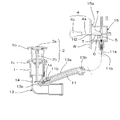
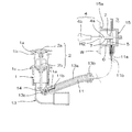
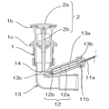
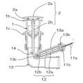
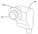
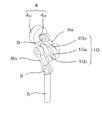
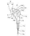
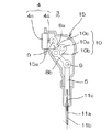
第一実施例の遠隔操作式排水栓装置の施工状態を示す断面図である。It is sectional drawing which shows the construction state of the remote control type drain plug apparatus of a 1st Example. 第一実施例の遠隔操作式排水栓装置の閉口時を示す参考図である。It is a reference figure which shows the time of closing of the remote control type drain plug device of a 1st Example. 第一実施例の遠隔操作式排水栓装置の開口時を示す参考図である。It is a reference figure showing the time of opening of the remote control type drain plug device of the first example. 第二実施例の遠隔操作式排水栓装置の施工状態を示す断面図である。It is sectional drawing which shows the construction state of the remote control type drain plug apparatus of a 2nd Example. 第二実施例の遠隔操作式排水栓装置の閉口時を示す参考図である。It is a reference figure which shows the time of closing of the remote control type drain plug device of 2nd Example. 第二実施例の遠隔操作式排水栓装置の押し操作を行った状態を示す参考図である。It is a reference figure which shows the state which performed pushing operation of the remote control type drain plug device of 2nd Example. 第二実施例の遠隔操作式排水栓装置の開口時を示す参考図である。It is a reference figure which shows the time of opening of the remote control type drain plug device of 2nd Example. 第三実施例の遠隔操作式排水栓装置の施工状態を示す断面図である。It is sectional drawing which shows the construction state of the remote control type drain plug apparatus of a 3rd Example. 第三実施例の遠隔操作式排水栓装置の閉口時を示す参考図である。It is a reference figure which shows the time of closing of the remote control type drain plug device of a 3rd Example. 第三実施例の遠隔操作式排水栓装置の開口時を示す参考図である。It is a reference figure which shows the time of opening of the remote control type drain plug device of a 3rd Example. 第三実施例の遠隔操作式排水栓装置の操作部を示す斜視図である。It is a perspective view which shows the operation part of the remote control type drain plug device of a 3rd Example. 第三実施例の遠隔操作式排水栓装置の操作部を示す参考図である。It is a reference figure which shows the operation part of the remote control type drain plug apparatus of a 3rd Example. 第三実施例の遠隔操作式排水栓装置の操作部の部材構成を示す参考図である。It is a reference figure which shows the member structure of the operation part of the remote control type drain plug device of a 3rd Example. 第三実施例の遠隔操作式排水栓装置の操作部の部材構成を示す参考図である。It is a reference figure which shows the member structure of the operation part of the remote control type drain plug device of a 3rd Example. 第三実施例の遠隔操作式排水栓装置の操作部の動作を示す参考図である。It is a reference figure which shows operation | movement of the operation part of the remote control type drain plug device of a 3rd Example. 第三実施例の遠隔操作式排水栓装置の操作部の動作を示す参考図である。It is a reference figure which shows operation | movement of the operation part of the remote control type drain plug device of a 3rd Example. 第三実施例の遠隔操作式排水栓装置の操作部の動作を示す参考図である。It is a reference figure which shows operation | movement of the operation part of the remote control type drain plug device of a 3rd Example. 第三実施例の遠隔操作式排水栓装置の操作部の動作を示す参考図である。It is a reference figure which shows operation | movement of the operation part of the remote control type drain plug device of a 3rd Example. 第三実施例の遠隔操作式排水栓装置の操作部の動作を示す参考図である。It is a reference figure which shows operation | movement of the operation part of the remote control type drain plug device of a 3rd Example.

以下に本発明の実施例について、図面を参照しつつ説明する。
尚、以下に記載する第一実施例及び第二実施例の説明において、「上方」「下方」とは、施工完了時における「上方」「下方」である。
また、「手前側」「奥側」とは、使用者が洗面台Sを使用する場合に使用者から見た状態での「手前側」「奥側」である。洗面ボウルBの排水口1aを基準とすると、平面視排水口1aからバックガード部Wに向かう方向が「奥側」であり、その反対の方向が「手前側」である。また、「前方」「後方」との記載を行う場合もあるが、この場合「前方」は「手前側」と、「後方」は「奥側」と、それぞれ同一の方向である。
また、レリースワイヤ11のインナーワイヤ11bや、該インナーワイヤ11bに連動するように動作する部材については、排水口1a側に移動することを「前進」、操作部3側に移動することを「後退」として記載してなる。
また、説明を容易にするため、第一実施例を示す図面のうち図2、図3、及び第二実施例を示す図面のうち図5乃至図7は排水口1a近傍と操作部3近傍の主要部材のみを図示する。
また、第三実施例を示す図面のうち、図9、図10は排水口1a近傍の主要部材のみを図示する。
Embodiments of the present invention will be described below with reference to the drawings.
In the description of the first embodiment and the second embodiment described below, “upper” and “lower” are “upper” and “lower” when construction is completed.
The “front side” and “back side” are “front side” and “back side” as viewed from the user when the user uses the washstand S. When the drainage port 1a of the wash bowl B is used as a reference, the direction from the planar drainage port 1a toward the back guard W is the “back side”, and the opposite direction is the “front side”. In some cases, “front” and “rear” are described. In this case, “front” is “front side” and “rear” is “back side” in the same direction.
Further, regarding the inner wire 11b of the release wire 11 and the member that operates so as to be interlocked with the inner wire 11b, the movement toward the drain port 1a is “forward”, and the movement toward the operation unit 3 is “backward”. ".
For ease of explanation, FIGS. 2 and 3 in the drawings showing the first embodiment, and FIGS. 5 to 7 in the drawings showing the second embodiment are the vicinity of the drain port 1a and the vicinity of the operation unit 3. Only the main members are shown.
Of the drawings showing the third embodiment, FIGS. 9 and 10 show only main members near the drain 1a.

以下に、本発明の第一実施例について、図面を参照しつつ説明する。
図1乃至図3に示した、本発明の第一実施例の遠隔操作式排水栓装置は、以下に記載する、槽体を備えた排水機器である洗面台Sに施工される排水栓装置であって、以下に記載する、排水口本体1、弁部材2、継手部材13、操作部3、レリースワイヤ11、排水管P、等の部材から構成されてなる。
洗面台Sは、以下に記載する、槽体である洗面ボウルBと、該洗面ボウルBを載架するキャビネット部Cと、から構成される。
洗面ボウルBは、上方が開口した箱体形状を成す槽体であって、その底面に、後述する排水口本体1を取り付ける取付口H1を備えてなる。
また、槽体部分の後方の上端部分から、上方に向かって垂立する壁面であるバックガード部Wを備えてなり、更に該バックガード部W上に、操作部3の操作体4の軸部4aを貫通させて取り付ける為の操作部用貫通孔H2を備えてなる。
キャビネット部Cは、上記洗面ボウルBを載架する箱体であって、上面は開放されて洗面ボウルBを載架するように構成されてなる。
排水口本体1は、略円筒形状の部材であって、その内部に排水口1aを形成してなる。また、その外側面上端には、周縁に沿って外周方向に突出するフランジ部1bを、また側面であってフランジ部1bより下方に雄ネジを、それぞれ備えてなる。また、上記排水口本体1の側面の雄ネジに螺合する雌ネジを備えた板ナット部材1cを備えてなる。
弁部材2は、略円盤状にして下面に環状のパッキングを備えた弁体2aと、該弁体2aの下面中央から垂下された弁軸部2bと、から構成されてなり、該弁部材2が降下し、環状のパッキングが排水口1a周縁に水密的に当接することで、排水口1aが弁体2aに覆われて閉口する。
継手部材13は、管体を略L字形状に屈曲させた部材であって、水平方向を向いた管体部分の内外を貫通するようにして筒状部13aが形成されてなり、この筒状部13aの上方の端部、即ち継手部材13の外側にある端部がレリースワイヤ11のアウターチューブ11a端部を接続固定する接続部13bである。また、筒状部13aの下方の端部、即ち継手部材13の内側にある端部は、後述する支持部14の方向を上方に変化させる突起部13cを備えてなる。施工完了時、継手部材13の上流側端部は排水口1a部材の下流側端部に、継手部材13の下流側端部は排水管Pに、それぞれ接続される。
支持部14は、舌状部分を備えた部材であって、施工完了時、レリースワイヤ11の、排水口1a側のインナーワイヤ11b端部に回動自在に接続された上で、上記継手部材13の筒状部13a内に配置される。
施工完了時、支持部14は、インナーワイヤ11bの進退動作に対応して進退動作する。具体的には、インナーワイヤ11bが排水口1a側に前進した状態では、支持部14は排水口1aの中心軸方向に突出すると共に、突起部13cによって先端の舌状部分が上方に向かって回動する。逆にインナーワイヤ11bが操作部3側に後退した状態では、支持部14はほぼその全体が筒状部13aの内部に収納され、先端の舌状部分も下方に向かって回動する。
操作部3は、バックガード部Wの操作部用貫通孔H2に取り付けられる部材であって、以下に記載する操作体4と、歯車部材6と、出力体5と、操作部本体15と、から構成される。
操作体4は、遠隔操作式排水栓装置の使用者が把持して押し引きの操作を行うツマミ部4bと、ツマミ部4bにネジによって接続される直線状の軸部4aと、から構成されてなる。
軸部4aについて詳述すると、軸部4aは円筒形状と長方体形状とを、棒状となるように組み合わせた部材であって、円筒部分側の端部にツマミ部4bを接続するネジを備えると共に、長方形形状を成す部分の下面に、直線状に歯合歯を備えたラック歯7を備えてなる。
操作体4の内、軸部4aの特にラック歯7を備えた部分が操作部本体15内部に備えられ、円筒部分が操作部本体15から突出してなり、操作部本体15を洗面台Sに取り付けた後、ツマミ部4bを軸部4aに接続することで操作体4として機能する。
出力体5は、軸方向視長方形形状を成す棒状の部材であって、その前方の側面に、直線状に歯合歯を並べたラック歯7を備えてなる。また出力体5の下端は、レリースワイヤ11のインナーワイヤ11b端部を接続することで、インナーワイヤ11bと一体の部材として機能するように構成されてなる(「出力体5とインナーワイヤ11bが一体の部材として機能する」とは、インナーワイヤ11bが、出力体5の上昇/下降の両方の動作に追従する、という意味である)。
歯車部材6は、操作体4のラック歯7と出力体5のラック歯7の両方に歯合する歯合歯を外周に備えた部材であって、操作体4に加えられた進退の操作を、歯車の回転を利用して異なる方向の進退運動に変換して出力体5側の進退動作として伝達する部材である。
操作部本体15は、上記操作体4の軸部4a、出力体5、歯車部材6をその内部に収納したケーシング体であって、工場等にて、操作部本体15として組み立てられた状態において、軸部4a及び出力体5を、所定の位置で所定の方向に進退、即ち往復直線運動を行うようにガイドする構成を備えてなる。
尚、軸部4aの一部、及び出力体5は前述のように、軸方向視長方形形状を成すように構成されており、これを利用して、上記操作部本体15内での進退動作の際に軸部4a及び出力体5が進退方向の側面側に回転し、歯車部材6と歯合しなくなることを防止するように構成されてなる。
また、軸部4a、即ち操作体4の進退の方向は、施工完了時における操作部本体15が取り付けられるバックガード部Wの前面に対して垂直を成す方向であり、出力体5の進退の方向は、操作部本体15が取り付けられるバックガード部Wの前面に対して略平行を成す方向であり、これは洗面台Sの設置面に対して垂直となる方向である。
また、操作部本体15として組み立てられた状態において、歯車部材6は、操作部本体15内部の所定の位置であって、外周に設けられた歯合歯が、操作体4及び出力体5のラック歯7に歯合した状態で操作部本体15内部に回動自在に配置されてなる。操作体4が進退すると、ラック歯7に歯合している歯合歯を備えた歯車部材6が回転し、この回転に伴って歯車部材6に歯合するラック歯7を備えた出力体5も進退を行う。
また、上記操作部本体15は、バックガード部Wの後面に当接する鍔部15aを備えてなり、この鍔部15aを貫通するビス部材(図示せず)を利用して、操作部本体15をバックガード部Wに固定するように構成してなる。
レリースワイヤ11は、操作体4に加えられた操作を、弁部材2側に伝達するための部材であって、筒状にして軸方向に剛性を、側面方向に可撓性を備えたアウターチューブ11aと、上記アウターチューブ11a内を摺動自在に動作する、軸方向に剛性を、側面方向に可撓性を備えたインナーワイヤ11bと、から構成される。
排水管Pは、継手部材13の下流側端部と床下配管とを接続する管体であって、その途中部分に管体をS字形状に屈曲させたトラップ部Tを備えてなる。
Below, the 1st example of the present invention is described, referring to drawings.
The remote-operated drain plug device according to the first embodiment of the present invention shown in FIGS. 1 to 3 is a drain plug device constructed on a wash basin S, which is a drain device having a tank body, as described below. Therefore, it is composed of members such as a drain port main body 1, a valve member 2, a joint member 13, an operation unit 3, a release wire 11, a drain pipe P, and the like described below.
The wash basin S is composed of a wash bowl B, which is a tank body, and a cabinet part C on which the wash bowl B is mounted.
The wash bowl B is a tank body having a box shape with an upper opening, and includes a mounting port H1 for attaching a drain port main body 1 to be described later on its bottom surface.
Moreover, the back guard part W which is a wall surface which hangs upward from the upper end part of the back of a tank part is provided, Furthermore, on this back guard part W, the axial part of the operation body 4 of the operation part 3 An operation portion through hole H2 is provided for attaching 4a through.
The cabinet portion C is a box on which the wash bowl B is mounted, and is configured to mount the wash bowl B with its upper surface opened.
The drain port body 1 is a substantially cylindrical member, and has a drain port 1a formed therein. Further, the upper end of the outer surface is provided with a flange portion 1b protruding in the outer peripheral direction along the periphery, and a male screw is provided on the side surface and below the flange portion 1b. Moreover, the plate nut member 1c provided with the internal thread engaged with the external thread of the side surface of the said drain-port main body 1 is provided.
The valve member 2 is configured by a valve body 2a having a substantially disk shape and having an annular packing on the lower surface, and a valve shaft portion 2b suspended from the center of the lower surface of the valve body 2a. Is lowered, and the annular packing comes into watertight contact with the periphery of the drain port 1a, so that the drain port 1a is covered with the valve body 2a and closed.
The joint member 13 is a member obtained by bending a tubular body into a substantially L shape, and a tubular portion 13a is formed so as to penetrate the inside and outside of the tubular portion facing in the horizontal direction. An upper end portion of the portion 13 a, that is, an end portion outside the joint member 13 is a connection portion 13 b for connecting and fixing the end portion of the outer tube 11 a of the release wire 11. Further, the lower end portion of the cylindrical portion 13a, that is, the end portion on the inner side of the joint member 13, is provided with a protruding portion 13c that changes the direction of the support portion 14 described later upward. When the construction is completed, the upstream end of the joint member 13 is connected to the downstream end of the drain port 1a member, and the downstream end of the joint member 13 is connected to the drain pipe P.
The support portion 14 is a member having a tongue-like portion. When the construction is completed, the support portion 14 is rotatably connected to the end portion of the inner wire 11b on the drain outlet 1a side of the release wire 11, and then the joint member 13 is connected. It arrange | positions in the cylindrical part 13a.
When the construction is completed, the support portion 14 moves back and forth in response to the back and forth operation of the inner wire 11b. Specifically, in a state where the inner wire 11b has advanced toward the drain port 1a, the support portion 14 protrudes in the central axis direction of the drain port 1a, and the tongue-shaped portion at the tip is rotated upward by the protrusion 13c. Move. On the contrary, in a state where the inner wire 11b is retracted toward the operation unit 3, the entire support unit 14 is accommodated inside the cylindrical portion 13a, and the tongue-shaped portion at the tip also rotates downward.
The operation portion 3 is a member attached to the operation portion through hole H2 of the back guard portion W, and includes an operation body 4, a gear member 6, an output body 5, and an operation portion main body 15 described below. Composed.
The operation body 4 includes a knob portion 4b that is gripped and pushed and pulled by a user of the remote-operated drain plug device, and a linear shaft portion 4a that is connected to the knob portion 4b with a screw. Become.
The shaft portion 4a will be described in detail. The shaft portion 4a is a member obtained by combining a cylindrical shape and a rectangular parallelepiped shape so as to form a rod shape, and includes a screw that connects the knob portion 4b to an end portion on the cylindrical portion side. At the same time, the rack teeth 7 having the teeth are linearly formed on the lower surface of the rectangular portion.
Of the operating body 4, a portion of the shaft portion 4 a provided with the rack teeth 7 is provided inside the operating portion body 15, and a cylindrical portion protrudes from the operating portion body 15, and the operating portion body 15 is attached to the washstand S After that, the knob portion 4b is connected to the shaft portion 4a to function as the operation body 4.
The output body 5 is a rod-shaped member having a rectangular shape in the axial direction, and includes rack teeth 7 in which teeth are arranged linearly on the front side surface thereof. The lower end of the output body 5 is configured to function as an integral member with the inner wire 11b by connecting the end of the inner wire 11b of the release wire 11 (“the output body 5 and the inner wire 11b are integrated. "It functions as a member of" means that the inner wire 11b follows both the upward and downward movements of the output body 5).
The gear member 6 is a member provided on the outer periphery with teeth that mesh with both the rack teeth 7 of the operation body 4 and the rack teeth 7 of the output body 5, and the forward and backward operation applied to the operation body 4 is performed. This is a member that converts the forward / backward movement in different directions using the rotation of the gears and transmits the forward / backward movement on the output body 5 side.
The operation unit body 15 is a casing body in which the shaft part 4a, the output body 5 and the gear member 6 of the operation body 4 are housed, and is assembled as the operation unit body 15 in a factory or the like. The shaft portion 4a and the output body 5 are configured to guide the shaft 4a so as to advance and retreat in a predetermined direction at a predetermined position, that is, to perform a reciprocating linear motion.
As described above, a part of the shaft portion 4a and the output body 5 are configured to have a rectangular shape when viewed in the axial direction. By using this, the advancing / retreating operation in the operation portion main body 15 is performed. At this time, the shaft portion 4a and the output body 5 are configured to be prevented from rotating to the side surface side in the advancing / retreating direction and being in mesh with the gear member 6.
Further, the shaft part 4a, that is, the direction of advancement / retraction of the operation body 4 is a direction perpendicular to the front surface of the back guard part W to which the operation part body 15 is attached at the time of completion of construction. Is a direction that is substantially parallel to the front surface of the back guard portion W to which the operation unit main body 15 is attached, and this is a direction that is perpendicular to the installation surface of the washstand S.
Further, in the state assembled as the operation unit main body 15, the gear member 6 is a predetermined position inside the operation unit main body 15, and the teeth provided on the outer periphery are racks of the operation body 4 and the output body 5. In a state of meshing with the teeth 7, the operation unit body 15 is rotatably arranged. When the operating body 4 advances and retreats, the gear member 6 provided with the tooth teeth meshed with the rack teeth 7 rotates, and the output body 5 provided with the rack teeth 7 meshed with the gear members 6 along with this rotation. Also advance and retreat.
The operation unit main body 15 includes a flange 15a that abuts the rear surface of the back guard unit W, and the operation unit main body 15 is moved using a screw member (not shown) that passes through the flange 15a. It is configured to be fixed to the back guard portion W.
The release wire 11 is a member for transmitting an operation applied to the operation body 4 to the valve member 2 side, and is a cylindrical outer tube having rigidity in the axial direction and flexibility in the side surface direction. 11a and an inner wire 11b that is slidably operated in the outer tube 11a and has rigidity in the axial direction and flexibility in the side surface direction.
The drainage pipe P is a pipe body that connects the downstream end of the joint member 13 and the underfloor pipe, and is provided with a trap part T that is bent in an S shape in the middle of the pipe.

上記のように構成された第一実施例の遠隔操作式排水栓装置は、以下のようにして、槽体である洗面ボウルBを備えた洗面台Sに施工される。尚、特に記載しないが、以下の施工の際において、必要に応じ各部材の接続箇所は接着又はパッキングを使用した接続等により、水密的に接続される。
また、本実施例において、操作部本体15は、工場などにて、その内部に操作体4、出力体5、歯車部材6を組み込んだ部材として加工した上で、施工現場などに搬入されたものとする。
まず、操作部本体15に配置された出力体5に、レリースワイヤ11のインナーワイヤ11bの操作部3側端部を接続した上で、アウターチューブ11aの操作部3側端部を操作部本体15に接続固定する。
次に、レリースワイヤ11のインナーワイヤ11bの排水口1a側端部に、支持部14を回動自在に接続した上で、支持部14を筒状部13aに挿入し、更に、レリースワイヤ11のアウターチューブ11aの排水口1a側端部を接続部13bに接続固定する。
次に、排水口本体1を上方から取付口H1に挿通し、取付口H1の周縁上面に、排水口本体1のフランジ部1b下面を当接した上で、排水口本体1の雄ネジに板ナット部材1cを螺合させて、取付口H1の周縁をフランジ部1bと板ナット部材1cとで挟持させて排水口本体1を取付口H1に接続固定する。
次に、操作部本体15から突出する軸部4aを、操作部用貫通孔H2から挿通させた上で、操作部本体15の鍔部15aを、洗面台Sのバックガード部Wに、後方側から当接させ、更に鍔部15aを貫通するビス部材を利用して、操作部本体15をバックガード部Wに固定する。
次に、継手部材13の上流側端部を排水口本体1に接続し、下流側端部を、排水管Pを介して床下配管に接続する。
最後に、操作部3の軸部4a端部に螺合にてツマミ部4bを固定した上で、排水口1aに弁部材2を配置して、本発明の第一実施例の遠隔操作式排水栓装置の施工が完了する。
The remote control type drain plug device of the first embodiment configured as described above is applied to a wash basin S provided with a wash bowl B which is a tank body as follows. In addition, although not particularly described, in the following construction, the connection locations of the respective members are connected in a watertight manner by bonding or using a packing or the like as necessary.
In the present embodiment, the operation unit main body 15 is processed at a factory or the like as a member in which the operation body 4, the output body 5, and the gear member 6 are incorporated, and then carried into a construction site or the like. And
First, after connecting the operation unit 3 side end of the inner wire 11b of the release wire 11 to the output body 5 arranged in the operation unit main body 15, the operation unit 3 side end of the outer tube 11a is connected to the operation unit main body 15. Secure the connection.
Next, the support part 14 is rotatably connected to the end of the inner wire 11b of the release wire 11 on the drain outlet 1a side, and the support part 14 is inserted into the cylindrical part 13a. The end of the outer tube 11a on the drain port 1a side is connected and fixed to the connecting portion 13b.
Next, the drain port main body 1 is inserted into the mounting port H1 from above, the lower surface of the flange portion 1b of the drain port main body 1 is brought into contact with the peripheral upper surface of the mounting port H1, and then the plate is attached to the male screw of the drain port main body 1 The nut member 1c is screwed together, and the periphery of the attachment port H1 is clamped between the flange portion 1b and the plate nut member 1c to connect and fix the drain port body 1 to the attachment port H1.
Next, after inserting the shaft portion 4a protruding from the operation portion main body 15 from the through hole H2 for operation portion, the flange portion 15a of the operation portion main body 15 is connected to the back guard portion W of the wash basin S on the rear side. The operation portion main body 15 is fixed to the back guard portion W by using a screw member that is in contact with each other and further penetrates the flange portion 15a.
Next, the upstream end of the joint member 13 is connected to the drain port main body 1, and the downstream end is connected to the underfloor pipe via the drain pipe P.
Finally, after the knob portion 4b is fixed to the end of the shaft portion 4a of the operation portion 3 by screwing, the valve member 2 is disposed at the drain port 1a, and the remotely operated drainage of the first embodiment of the present invention. Construction of the stopper device is completed.

上記のように施工された第一実施例の遠隔操作式排水栓装置を使用する場合、まず操作部3の操作体4に操作を加え、図2にあるように、排水口1aが閉口した状態とする。
この時、操作部3の操作体4は手前側に引き出され、出力体5は上昇し、出力体5に接続されているインナーワイヤ11bは操作部3側に後退している。また、インナーワイヤ11bに接続されている支持部14も操作部3側に後退して弁部材2の弁軸部2b下端から離間している。このため、弁部材2は自重により降下し、弁部材2の弁体2a下面が排水口1aの周縁に水密的に当接することで、排水口1aを閉口してなる。
この状態から操作部3の操作体4に押し込み操作を行うと、操作体4は奥側に進み、操作体4のラック歯7と歯合している歯車部材6が回転し、この回転により歯車部材6に歯合しているラック歯7を有する出力体5が降下する。出力体5が降下すると、出力体5に接続されているインナーワイヤ11bが排水口1a側に前進し、インナーワイヤ11bの排水口1a側端部に回動自在に接続されている支持部14が、排水口1a側に前進すると共に突起部13cに当たって支持部14の先端側が上方に回動し、弁部材2の弁軸下端に当接して弁軸ごと弁部材2を押し上げるため、弁体2aが排水口1a周縁から離間し、図3に示したように、排水口1aが開口する。
槽体である洗面ボウルB内部に吐水又は排水があった場合、吐水又は排水は、排水口1aから、排水口本体1内部、継手部材13、トラップ部Tを備えた排水管Pを介して、最終的には床下配管から下水側に排出される。また、トラップ部T内に排水が溜まると、トラップ部T内に封水と呼ばれる排水による溜まり水が生じる。この封水が、排水の流路上に満水部分を発生させ、この満水部分を下水側からの臭気や害虫類が逆流できないため、トラップ部Tにより下水側からの臭気や害虫類が屋内側に侵入することを防止することができる。
この排水口1aが開口した状態より、操作部3の操作体4に引き操作を行うと、操作体4は手前側に移動し、操作体4の軸部4aのラック歯7と歯合している歯車部材6が回転し、この回転により歯車部材6に歯合しているラック歯7を有する出力体5が上昇する。出力体5が上昇すると、出力体5に接続されているインナーワイヤ11bが操作部3側に後退し、インナーワイヤ11bの排水口1a側端部に回動自在に接続されている支持部14が筒状部13a内に移動して、支持部14が弁部材2の弁軸下端から離間する。このため、弁部材2は自重により降下し、弁部材2の弁体2a下面が排水口1aの周縁に水密的に当接して、排水口1aを閉口する。
以降、排水口1aが閉口した状態の時に操作体4に押し込み操作を加えることで排水口1aは開口し、排水口1aが開口した状態の時に操作体4に引き操作を行うことで排水口1aを閉口することができる。
When using the remote-operated drain plug device of the first embodiment constructed as described above, first, the operation body 4 of the operation unit 3 is operated, and the drain port 1a is closed as shown in FIG. And
At this time, the operation body 4 of the operation unit 3 is pulled out to the near side, the output body 5 is raised, and the inner wire 11b connected to the output body 5 is retracted to the operation unit 3 side. Further, the support portion 14 connected to the inner wire 11b is also retracted toward the operation portion 3 and is separated from the lower end of the valve shaft portion 2b of the valve member 2. Therefore, the valve member 2 is lowered by its own weight, and the lower surface of the valve body 2a of the valve member 2 is in watertight contact with the periphery of the drain port 1a, thereby closing the drain port 1a.
When a pushing operation is performed on the operating body 4 of the operating unit 3 from this state, the operating body 4 advances to the back side, and the gear member 6 meshed with the rack teeth 7 of the operating body 4 rotates, and this rotation causes the gears to rotate. The output body 5 having the rack teeth 7 meshed with the member 6 is lowered. When the output body 5 is lowered, the inner wire 11b connected to the output body 5 moves forward to the drain port 1a side, and the support portion 14 that is rotatably connected to the end portion of the inner wire 11b on the drain port 1a side is provided. The valve body 2a moves forward to the drain port 1a side and contacts the protrusion 13c so that the tip end side of the support portion 14 is rotated upward to contact the lower end of the valve shaft of the valve member 2 to push up the valve member 2 together with the valve shaft. The drain port 1a opens away from the periphery of the drain port 1a as shown in FIG.
When there is water discharge or drainage inside the wash bowl B which is a tank body, the water discharge or drainage is performed from the drain port 1a through the drain pipe P provided with the drain port body 1 inside, the joint member 13, and the trap part T. Finally, it is discharged from the underfloor piping to the sewage side. Further, when drainage is accumulated in the trap portion T, accumulated water is generated in the trap portion T due to drainage called sealed water. This sealed water generates a full part on the drainage flow path, and odors and pests from the sewage side cannot flow back through the full part, so the trap part T allows odors and pests from the sewage side to enter the indoor side. Can be prevented.
When the operation body 4 of the operation section 3 is pulled from the state where the drainage port 1a is opened, the operation body 4 moves to the near side and meshes with the rack teeth 7 of the shaft section 4a of the operation body 4. The gear member 6 is rotated, and the output body 5 having the rack teeth 7 meshed with the gear member 6 is raised by this rotation. When the output body 5 is raised, the inner wire 11b connected to the output body 5 is retracted to the operation section 3 side, and the support section 14 that is rotatably connected to the end of the inner wire 11b on the drain port 1a side is provided. The support part 14 moves away from the lower end of the valve shaft of the valve member 2 by moving into the cylindrical part 13a. For this reason, the valve member 2 descends due to its own weight, and the lower surface of the valve body 2a of the valve member 2 comes into watertight contact with the periphery of the drain port 1a to close the drain port 1a.
Thereafter, when the drain port 1a is closed, a push operation is applied to the operation body 4 to open the drain port 1a, and when the drain port 1a is open, the operation body 4 is pulled to perform a drain operation. Can be closed.

次に、本発明の第二実施例について、図面を参照しつつ説明する。
図4乃至図7に示した、本発明の第二実施例の遠隔操作式排水栓装置は、以下に記載する、槽体を備えた排水機器である洗面台Sに施工されるものであって、以下に記載する、排水口本体1、支持部材18、弁部材2、継手部材13、オーバーフロー本体16、操作部3、レリースワイヤ11、排水管P、等の部材から構成されてなる。
洗面台Sは、以下に記載する、槽体である洗面ボウルBと、該洗面ボウルBを載架するキャビネット部Cと、から構成される。
洗面ボウルBは、上方が開口した箱体形状を成す槽体であって、その底面に、後述する排水口本体1を取り付ける取付口H1を備えてなる。
また、洗面ボウルB内の側面上方に、オーバーフロー本体16を取り付けるための、正面視長方形形状を成すオーバーフロー取付口H3を備えてなる。
また、槽体部分の後方の上端部分から、上方に向かって垂立する壁面であるバックガード部Wを備えてなる。
キャビネット部Cは、上記洗面ボウルBを載架する箱体であって、上面は開放されて洗面ボウルBを載架するように構成されてなる。
排水口本体1は、略円筒形状の部材であって、その内部には排水口1aを形成してなる。また、その外側面上端には、周縁に沿って外周方向に突出するフランジ部1bを、また側面であって中間位置より下方には雄ネジを、それぞれ備えてなる。
また排水口本体1の内部には、支持部材18と嵌合する凸部1dを内周周縁に沿って複数個備えてなる。
支持部材18は、排水口本体1の内部にレリースワイヤ11を配置固定するための部材であって、中央部分に、略筒形状であって、その内部にレリースワイヤ11のインナーワイヤ11b端部を進退自在に挿通すると共に、その下端にアウターチューブ11a端部を接続固定する保持部を備えてなる。また、保持部の周囲に、排水口本体1の凸部1dと嵌合する弾性爪18bを備えた環状部18aを設けてなる。
弁部材2は、略円盤状にして下面に環状のパッキングを備えた弁体2aと、該弁体2aの下面中央に設けた、レリースワイヤ11のインナーワイヤ11b先端の嵌合部11dに嵌合する被嵌合部2cを備えてなり、該弁部材2が降下して環状のパッキング部分にて排水口1a上縁近傍を覆うことで排水口1aを閉口する。
継手部材13は、管体を略L字形状に屈曲させた部材であって、更に継手部材13の側面に円筒形状を成す枝管部13dを設けてなる。
また、継手部材13の上流側の端部には、排水口本体1の雄ネジと螺合する雌ネジを備えてなり、施工完了時、継手部材13の上流側端部は排水口1a部材の下流側端部に、継手部材13の下流側端部は排水管Pに、それぞれ接続される。
オーバーフロー本体16は、側面視略T字形状を成す管体であって、オーバーフロー取付口H3に合致する内径形状を備えた開口を有するオーバーフロー排水口16aと、該オーバーフロー排水口16aから下方を向いて延出されたオーバーフロー排出口16bと、オーバーフロー排水口16a内に備えられた、操作部3の操作部本体15を保持固定する操作部保持部16cと、から構成される。
また、オーバーフロー排出口16bから継手部材13の枝管部13dまでを水密的に接続するチューブ管17を備えてなる。
操作部3は、洗面ボウルBのオーバーフロー本体16に取り付けられて、排水口1aの開閉を操作する部材であって、以下に記載する操作体4と、ヒンジ部材8と、出力体5と、操作部本体15と、スプリング部材(図示せず)と、から構成される。
操作体4は、遠隔操作式排水栓装置の使用者が押し操作を行うボタン部4cと、ボタン部4cに嵌合固定される直線状の軸部4aと、軸部4aの端部に設けられた、後述するヒンジ部材8の一端にヒンジを用いた構造にて回動自在に軸着される回動部9と、から構成されてなる。
ボタン部4cは、略直方体形状を成す、オーバーフロー排水口16aの内外を進退する部材であって、下方及び後方には壁面が無く、開放されてなる。
出力体5は、棒状の部材であって、その上端に、後述するヒンジ部材8の一端(操作体4との接続箇所とは逆側の端部)にヒンジを用いた構造にて回動自在に軸着される回動部9を備えてなる。
ヒンジ部材8は、棒状の部材であって、その両端にそれぞれヒンジを備えてなる。一端のヒンジは、上記操作体4の軸部4aに回動自在に軸着されて回動部9を成し、他端のヒンジは、出力体5の回動部9に回動自在に軸着されて回動部9を成してなる。
操作部本体15は、上記操作体4の軸部4aの一部、出力体5の一部、ヒンジ部材8をその内部に収納したケーシング体であって、工場等にて、操作部本体15として組み立てられた状態において、軸部4a及び出力体5については所定の位置で所定の方向に進退、即ち往復直線運動を行うように構成されてなる。
また、軸部4a、即ち操作体4の進退の方向は、施工完了時における操作部本体15が取り付けられる洗面ボウルBの奥側の壁面に対して垂直を成す方向であり、出力体5の進退の方向は、操作部本体15が取り付けられる洗面ボウルBの奥側の壁面に対して略平行を成す方向であり、これは洗面台Sの設置面に対して垂直となる方向である。
また、操作部本体15として組み立てられた状態において、ヒンジ部材8は、操作体4及び出力体5の進退に対応した動作により、操作体4の軸部4aに対しておよそ45度から90度の範囲で回動動作する。
スプリング部材は、上記操作体4の軸部4a周囲に配置される部材であって、操作体4を洗面ボウルBの手前側(図4の左側)に常時付勢するように配置される。
レリースワイヤ11は、操作体4に加えられた操作を、弁部材2側に伝達するための部材であって、筒状にして軸方向に剛性を、側面方向に可撓性を備えたアウターチューブ11aと、上記アウターチューブ11a内を摺動自在に動作する、軸方向に剛性を、側面方向に可撓性を備えたインナーワイヤ11bと、インナーワイヤ11bをアウターチューブ11aに対し、操作部3側に付勢する戻りスプリング(図示せず)と、から構成される。
また、インナーワイヤ11bの排水口1a側の端部には、弁部材2の被嵌合部2cと嵌合する、弁軸を兼ねた嵌合部11dを備えてなる。
ロック部材12は、ケーシング部12aと、該ケーシング部12aに進退自在に備えられる支持軸と、を備えた部材であって、レリースワイヤ11端部に接続され、ケーシング部12a内に備えた機構によって、施工完了時、支持軸の上端に押し込み操作を加える都度、支持軸が降下し、インナーワイヤ11bを排水口1a側に前進させた状態で固定/固定を解除し、レリースワイヤ11の戻りスプリングの作用によってインナーワイヤ11bの後退と共に支持軸が上昇、を交互に繰り返すロック機構を備えた部材である。
尚、施工が完了した状態において、インナーワイヤ11bの操作部3側端部は、ロック部材12の支持軸に接続固定されてはいないが、レリースワイヤ11の戻りスプリングの作用によって、同一軸線上を連動して往復運動しており、支持軸に加えられた動作は、インナーワイヤ11bの操作部3側端部に伝達され、支持軸が降下して固定されている状態ではインナーワイヤ11bが前進し、支持軸の固定が解除されている状態では支持軸とインナーワイヤ11bは共に後退する、というように、支持軸に加えられた操作はインナーワイヤ11bに伝達される。
また、上記ロック部材12は、施工完了時、操作部本体15の出力体5側の端部に接続される。
この接続において、操作部本体15はロック部材12のケーシング部12aに接続固定される。
出力体5と支持軸は、同一軸線上、即ち支持軸の往復の方向と、出力体5の往復の方向とは同一であり、且つ両者は対向する位置関係に配置固定される。操作体4に押し込み操作が加えられ、それに対応して出力体5が下方に突出すると、出力体5は支持軸の上端に当接して、支持軸に下方への押し込み操作を加えるように配置される。
上述のように、支持軸に加えられた動作はインナーワイヤ11bに伝達されることから、本実施例においては、出力体5の動作は、支持軸を介してインナーワイヤ11bの操作部3側端部に伝達されてなる。
排水管Pは、継手部材13の下流側端部と床下配管とを接続する管体であって、その途中部分に管体をS字形状に屈曲させたトラップ部Tを備えてなる。
Next, a second embodiment of the present invention will be described with reference to the drawings.
The remote-operated drain plug device according to the second embodiment of the present invention shown in FIGS. 4 to 7 is constructed on a wash basin S which is a drainage device having a tank body described below. The drain port body 1, the support member 18, the valve member 2, the joint member 13, the overflow body 16, the operation unit 3, the release wire 11, the drain pipe P, and the like described below.
The wash basin S is composed of a wash bowl B, which is a tank body, and a cabinet part C on which the wash bowl B is mounted.
The wash bowl B is a tank body having a box shape with an upper opening, and includes a mounting port H1 for attaching a drain port main body 1 to be described later on its bottom surface.
Further, an overflow attachment port H3 having a rectangular shape in front view for attaching the overflow main body 16 is provided above the side surface in the wash bowl B.
Moreover, the back guard part W which is a wall surface which hangs upwards from the upper end part of the back of a tank part is provided.
The cabinet portion C is a box on which the wash bowl B is mounted, and is configured to mount the wash bowl B with its upper surface opened.
The drain port body 1 is a substantially cylindrical member, and has a drain port 1a formed therein. Further, the upper end of the outer surface is provided with a flange portion 1b protruding in the outer peripheral direction along the periphery, and a male screw is provided on the side surface and below the intermediate position.
Further, the drain port body 1 is provided with a plurality of convex portions 1d fitted to the support member 18 along the inner peripheral edge.
The support member 18 is a member for disposing and fixing the release wire 11 inside the drain outlet main body 1. The support member 18 has a substantially cylindrical shape at the center portion, and the end portion of the inner wire 11 b of the release wire 11 is placed inside the support member 18. The holder is inserted so as to be able to advance and retreat, and a holding portion for connecting and fixing the end of the outer tube 11a is provided at the lower end thereof. In addition, an annular portion 18 a having an elastic claw 18 b that fits with the convex portion 1 d of the drain port body 1 is provided around the holding portion.
The valve member 2 is fitted into a valve body 2a having a substantially disk shape and having an annular packing on the lower surface, and a fitting portion 11d at the tip of the inner wire 11b of the release wire 11 provided at the center of the lower surface of the valve body 2a. The valve member 2 is lowered and covers the vicinity of the upper edge of the drainage port 1a at the annular packing portion to close the drainage port 1a.
The joint member 13 is a member obtained by bending a tubular body into a substantially L-shape, and further includes a branch pipe portion 13 d having a cylindrical shape on the side surface of the joint member 13.
Further, the upstream end of the joint member 13 is provided with a female screw that is screwed with the male screw of the drain port body 1, and when the construction is completed, the upstream end of the joint member 13 is the drain port 1a member. The downstream end of the joint member 13 is connected to the drain pipe P at the downstream end.
The overflow main body 16 is a tubular body having a substantially T shape in a side view, and has an overflow drain port 16a having an opening having an inner diameter matching the overflow mounting port H3, and facing downward from the overflow drain port 16a. The extended overflow outlet 16b and the operation part holding part 16c provided in the overflow drain 16a for holding and fixing the operation part main body 15 of the operation part 3 are configured.
Further, a tube pipe 17 is provided for watertightly connecting the overflow discharge port 16b to the branch pipe portion 13d of the joint member 13.
The operation unit 3 is a member that is attached to the overflow body 16 of the wash bowl B and operates to open and close the drain port 1a. The operation body 4, the hinge member 8, the output body 5, and the operation described below It is comprised from the part main body 15 and a spring member (not shown).
The operation body 4 is provided at a button portion 4c that is pressed by a user of the remote-operated drain plug device, a linear shaft portion 4a that is fitted and fixed to the button portion 4c, and an end portion of the shaft portion 4a. In addition, the rotating member 9 is pivotally mounted in a structure using a hinge at one end of a hinge member 8 to be described later.
The button portion 4c is a member that has a substantially rectangular parallelepiped shape, and advances and retreats in and out of the overflow drainage port 16a.
The output body 5 is a rod-like member, and at the upper end thereof, the output body 5 can be freely rotated by a structure using a hinge at one end of a hinge member 8 to be described later (an end portion on the opposite side to the connection portion with the operation body 4). It is provided with a rotating portion 9 that is pivotally attached to the shaft.
The hinge member 8 is a rod-shaped member and has hinges at both ends thereof. The hinge at one end is pivotally attached to the shaft portion 4 a of the operation body 4 to form a turning portion 9, and the hinge at the other end is pivoted to the turning portion 9 of the output body 5. The rotating part 9 is formed by being worn.
The operation unit main body 15 is a casing body in which a part of the shaft part 4a of the operation body 4, a part of the output body 5, and the hinge member 8 are housed, and is used as the operation unit main body 15 in a factory or the like. In the assembled state, the shaft portion 4a and the output body 5 are configured to advance and retreat in a predetermined direction at a predetermined position, that is, perform a reciprocating linear motion.
In addition, the shaft 4a, that is, the direction of advancement / retraction of the operation body 4 is a direction perpendicular to the wall surface on the back side of the wash bowl B to which the operation part main body 15 is attached at the time of completion of construction. The direction is a direction that is substantially parallel to the inner wall surface of the wash bowl B to which the operation unit main body 15 is attached. This is a direction that is perpendicular to the installation surface of the wash basin S.
Further, in the assembled state as the operation unit main body 15, the hinge member 8 is about 45 degrees to 90 degrees with respect to the shaft portion 4 a of the operation body 4 by the operation corresponding to the advancement and retreat of the operation body 4 and the output body 5. It rotates in the range.
The spring member is a member disposed around the shaft portion 4a of the operation body 4, and is disposed so as to constantly urge the operation body 4 toward the front side of the wash bowl B (left side in FIG. 4).
The release wire 11 is a member for transmitting an operation applied to the operation body 4 to the valve member 2 side, and is a cylindrical outer tube having rigidity in the axial direction and flexibility in the side surface direction. 11a, an inner wire 11b that is slidable in the outer tube 11a, has rigidity in the axial direction, and has flexibility in the side surface direction, and the inner wire 11b with respect to the outer tube 11a on the operation unit 3 side And a return spring (not shown) for urging the spring.
Further, an end portion of the inner wire 11b on the drain port 1a side is provided with a fitting portion 11d that also fits with the fitted portion 2c of the valve member 2 and also serves as a valve shaft.
The lock member 12 is a member that includes a casing portion 12a and a support shaft that is provided in the casing portion 12a so as to be able to advance and retract. The lock member 12 is connected to the end of the release wire 11 and is provided by a mechanism provided in the casing portion 12a. When the construction is completed, each time a pushing operation is applied to the upper end of the support shaft, the support shaft descends, and the inner wire 11b is advanced to the drain port 1a side to be fixed / released, and the release wire 11 return spring This is a member provided with a lock mechanism that alternately repeats raising and lowering of the support shaft as the inner wire 11b retracts due to the action.
In addition, in the state where the construction is completed, the end of the inner wire 11b on the side of the operation unit 3 is not connected and fixed to the support shaft of the lock member 12, but the return spring of the release wire 11 acts on the same axis. The reciprocating motion is interlocked and the operation applied to the support shaft is transmitted to the end of the inner wire 11b on the side of the operation unit 3, and the inner wire 11b moves forward when the support shaft is lowered and fixed. The operation applied to the support shaft is transmitted to the inner wire 11b such that both the support shaft and the inner wire 11b are retracted in a state where the fixing of the support shaft is released.
Further, the lock member 12 is connected to the end of the operation unit body 15 on the output body 5 side when the construction is completed.
In this connection, the operation portion main body 15 is connected and fixed to the casing portion 12 a of the lock member 12.
The output body 5 and the support shaft are on the same axis, that is, the reciprocating direction of the support shaft and the reciprocating direction of the output body 5 are the same, and both are disposed and fixed in an opposing positional relationship. When the push operation is applied to the operation body 4 and the output body 5 protrudes downward correspondingly, the output body 5 is arranged to abut on the upper end of the support shaft and to apply the push operation downward to the support shaft. The
As described above, since the operation applied to the support shaft is transmitted to the inner wire 11b, in the present embodiment, the operation of the output body 5 is performed at the end of the inner wire 11b on the operation unit 3 side via the support shaft. It is transmitted to the part.
The drainage pipe P is a pipe body that connects the downstream end of the joint member 13 and the underfloor pipe, and is provided with a trap part T that is bent in an S shape in the middle of the pipe.

上記のように構成された第二実施例の遠隔操作式排水栓装置は、以下のようにして、槽体である洗面ボウルBを備えた洗面台Sに施工される。尚、特に記載しないが、以下の施工の際において、必要に応じ各部材の接続箇所は接着又はパッキングを使用した接続等により、水密的に接続される。
また、本実施例において、操作部本体15は、工場などにて、その内部に操作体4、出力体5、ヒンジ部材8、スプリング部材を組み込んだ部材として加工した上で、施工現場などに搬入されたものとする。
まず、チューブ管17の一端をオーバーフロー本体16のオーバーフロー排出口16bに、他端を継手部材13の枝管部13dに、それぞれ水密的に接続する。
次に、オーバーフロー本体16のオーバーフロー排水口16aを洗面ボウルBのオーバーフロー取付口H3に取り付ける。
次に、排水口本体1を上方から取付口H1に挿通し、取付口H1の周縁上面に、排水口本体1のフランジ部1b下面を当接した上で、排水口本体1の雄ネジに継手部材13の雌ネジを螺合させて、取付口H1の周縁をフランジ部1bと継手部材13とで挟持させて排水口本体1を取付口H1に接続固定する。
次に、継手部材13の下流側端部を、排水管Pを介して床下配管に接続する。
次に、操作部本体15の出力体5に支持軸上端が対向するようにして、ロック部材12を操作部本体15に接続し、更に支持軸の下端がインナーワイヤ11bの操作部3側端部に当接するように配置した上で、アウターチューブ11aの操作部3側端部をロック部材12のケーシング部12aに接続固定する。
次に、レリースワイヤ11の排水口1a側端部をオーバーフロー排水口16aからオーバーフロー排出口16b、チューブ管17、枝管部13dの順に挿通し、レリースワイヤ11の端部を継手部材13内部に配置した上で、操作部本体15をオーバーフロー本体16の操作部保持部16cに保持固定させる。
次に、レリースワイヤ11の排水口部3側端部を継手部材13内部から排水口本体1内部より洗面ボウルB内に引き上げる。
次に、支持部材18にアウターチューブ11aの排水口1a側端部を固定した上で、排水口本体1の凸部1dと支持部材18の弾性爪18bを嵌合させて、排水口本体1に支持部材18を接続固定する。
最後に、操作体4の軸部4aにボタン部4cを嵌合させると共に、インナーワイヤ11b先端の嵌合部11dに弁部材2の被嵌合部2cを嵌合させて、本発明の第二実施例の遠隔操作式排水栓装置の施工が完了する。
The remote-operated drain plug device of the second embodiment configured as described above is applied to a wash basin S including a wash bowl B that is a tank body as follows. In addition, although not particularly described, in the following construction, the connection locations of the respective members are connected in a watertight manner by bonding or using a packing or the like as necessary.
Further, in this embodiment, the operation unit main body 15 is processed as a member incorporating the operation body 4, the output body 5, the hinge member 8 and the spring member therein at a factory or the like, and then carried into a construction site or the like. It shall be assumed.
First, one end of the tube pipe 17 is connected to the overflow outlet 16b of the overflow body 16 and the other end is connected to the branch pipe portion 13d of the joint member 13 in a watertight manner.
Next, the overflow drain port 16a of the overflow body 16 is attached to the overflow attachment port H3 of the wash bowl B.
Next, the drain port body 1 is inserted into the mounting port H1 from above, the lower surface of the flange portion 1b of the drain port body 1 is brought into contact with the peripheral upper surface of the mounting port H1, and the joint is connected to the male screw of the drain port body 1 The female screw of the member 13 is screwed together, and the peripheral edge of the attachment port H1 is sandwiched between the flange portion 1b and the joint member 13 to connect and fix the drain port body 1 to the attachment port H1.
Next, the downstream end of the joint member 13 is connected to the underfloor pipe via the drain pipe P.
Next, the lock member 12 is connected to the operation unit main body 15 so that the upper end of the support shaft faces the output body 5 of the operation unit main body 15, and the lower end of the support shaft is the end of the inner wire 11b on the operation unit 3 side. The operation tube 3 side end of the outer tube 11 a is connected and fixed to the casing 12 a of the lock member 12.
Next, the end of the release wire 11 on the drain outlet 1a side is inserted from the overflow outlet 16a to the overflow outlet 16b, the tube tube 17, and the branch pipe portion 13d in this order, and the end of the release wire 11 is disposed inside the joint member 13. After that, the operation unit main body 15 is held and fixed to the operation unit holding unit 16 c of the overflow main body 16.
Next, the drain port 3 side end of the release wire 11 is pulled up from the inside of the joint member 13 into the wash bowl B from the drain port main body 1 inside.
Next, after fixing the drain port 1a side end of the outer tube 11a to the support member 18, the convex portion 1d of the drain port body 1 and the elastic claw 18b of the support member 18 are fitted to the drain port body 1. The support member 18 is connected and fixed.
Finally, the button portion 4c is fitted to the shaft portion 4a of the operating body 4, and the fitted portion 2c of the valve member 2 is fitted to the fitting portion 11d at the tip of the inner wire 11b. Construction of the remote control drain plug device of the embodiment is completed.

上記のように施工された第二実施例の遠隔操作式排水栓装置を使用する場合、まず操作部3の操作体4に操作を加え、図5に示したように、排水口1aが閉口した状態とする。
この時、操作部3の操作体4は、スプリング部材の作用により手前側に引き出され、出力体5は上昇している。一方、インナーワイヤ11b及び支持軸は、レリースワイヤ11の戻りスプリングの作用と、弁部材2の自重により、インナーワイヤ11bが操作部3側に後退し、支持軸もインナーワイヤ11bに当接して押し上げられて上昇した状態となっている。
上記のように弁部材2は、弁部材2の自重と、戻りスプリングの付勢により降下し、弁部材2の弁体2a下面が排水口1aの周縁に水密的に当接することで、排水口1aを閉口してなる。
この状態から操作部3の操作体4に押し込み操作を行うと、操作体4は奥側に進み、ヒンジ部材8が操作体4の軸部4aに対し45度を成す角度から、90度を成す角度に回動して、出力体5が降下する。出力体5の下端は、ロック部材12の支持軸上端に当接して支持軸に押し込み操作を行うため、支持軸が降下し、ロック機構が働いて、インナーワイヤ11bを排水口1a側に前進させた状態で固定する。これにより、排水口1a付近では、インナーワイヤ11bと共に弁部材2が上昇し、排水口1a周縁から弁体2aが離間して、図6に示したように、排水口1aが開口する。
尚、操作部3の操作体4は、使用者の押し込み操作が終わって使用者の指等が離されると、スプリング部材の作用によって、当初の状態、即ち手前側に引き出された状態に戻る。操作体4が当初の位置に戻ったことによって、ヒンジ部材8は操作体4に対して45度を成す当初の位置に、出力体5も上昇して当初の位置に、それぞれ戻る。これにより、図7に示したように、排水口1aは開口し、ロック部材12の支持軸12bは降下したまま、操作部の各部材は当初の位置に戻る。
槽体である洗面ボウルB内部に吐水又は排水があった場合、吐水又は排水は、排水口1aから、排水口本体1内部、継手部材13、トラップ部Tを備えた排水管Pを介して、最終的には床下配管から下水側に排出される。また、トラップ部T内に排水が溜まると、トラップ部T内に封水と呼ばれる排水による溜まり水が生じる。この封水が、排水の流路上に満水部分を発生させ、この満水部分を下水側からの臭気や害虫類が逆流できないため、トラップ部Tにより下水側からの臭気や害虫類が屋内側に侵入することを防止することができる。
この排水口1aが開口した状態より、操作部3の操作体4に再度押し込み操作を行うと、再び、図6に示した状態となり、開口時と同様に、出力体5の下端は、ロック部材12の支持軸上端に当接して支持軸に押し込み操作を行うため、ロック機構が再度機能して支持軸の固定が解除される。
使用者の操作体4への押し込み操作が終わって使用者の指等が離されると、スプリング部材の作用によって、操作体4、ヒンジ部材8、出力体5は当初の位置に戻ると共に、支持軸の固定が解除されたことで、レリースワイヤ11の戻りスプリング11cの作用と、弁部材2の自重により、弁部材2が降下し、弁体2a下面が排水口1aの周縁に水密的に当接して、図5に示した状態に戻り、排水口1aが再び閉口される。
以降、操作体4に押し込み操作を行う毎に、排水口1aを閉口/排水口1aを開口、を交互に繰り返すことができる。
また、排水口1aを閉口した状態において、洗面ボウルB内に吐水又は排水を行い、吐水又は排水を溜めた場合、吐水又は排水の水位は上昇してゆくが、水位がオーバーフロー排水口16aの下端に達すると、吐水又は排水は、ボタン部4cの下面からオーバーフロー排水口16a、オーバーフロー排出口16b、チューブ管17、枝管部13dを介し、継手部材13内部から、トラップ部Tを備えた排水管Pを介して、最終的には床下配管から下水側に排出されるため、吐水又は排水が、槽体である洗面ボウルBの上面から溢れることはない。
When using the remote control type drain plug device of the second embodiment constructed as described above, first, the operation body 4 of the operation unit 3 is operated, and the drain port 1a is closed as shown in FIG. State.
At this time, the operation body 4 of the operation unit 3 is pulled out to the near side by the action of the spring member, and the output body 5 is raised. On the other hand, the inner wire 11b and the support shaft are pushed up by the action of the return spring of the release wire 11 and the weight of the valve member 2 so that the inner wire 11b is retracted toward the operation unit 3 and the support shaft is also in contact with the inner wire 11b. It has been raised.
As described above, the valve member 2 is lowered by the weight of the valve member 2 and the biasing force of the return spring, and the lower surface of the valve body 2a of the valve member 2 is in watertight contact with the peripheral edge of the drain port 1a. 1a is closed.
When a pushing operation is performed on the operating body 4 of the operating unit 3 from this state, the operating body 4 advances to the back side, and the hinge member 8 forms 90 degrees from an angle of 45 degrees with respect to the shaft part 4a of the operating body 4. The output body 5 is lowered by rotating to an angle. Since the lower end of the output body 5 abuts on the upper end of the support shaft of the lock member 12 and pushes into the support shaft, the support shaft is lowered and the lock mechanism operates to advance the inner wire 11b toward the drain port 1a. Fix it in the state. Thereby, in the vicinity of the drain port 1a, the valve member 2 rises together with the inner wire 11b, the valve body 2a is separated from the periphery of the drain port 1a, and the drain port 1a is opened as shown in FIG.
When the user's pushing operation is completed and the user's finger is released, the operating body 4 of the operation unit 3 returns to the initial state, that is, the state of being pulled out to the near side by the action of the spring member. When the operating body 4 returns to the initial position, the hinge member 8 returns to the initial position at 45 degrees with respect to the operating body 4 and the output body 5 also rises and returns to the initial position. Thereby, as shown in FIG. 7, the drain port 1a is opened, and the members of the operation unit return to the initial positions while the support shaft 12b of the lock member 12 is lowered.
When there is water discharge or drainage inside the wash bowl B which is a tank body, the water discharge or drainage is performed from the drain port 1a through the drain pipe P provided with the drain port body 1 inside, the joint member 13, and the trap part T. Finally, it is discharged from the underfloor piping to the sewage side. Further, when drainage is accumulated in the trap portion T, accumulated water is generated in the trap portion T due to drainage called sealed water. This sealed water generates a full part on the drainage flow path, and odors and pests from the sewage side cannot flow back through the full part, so the trap part T allows odors and pests from the sewage side to enter the indoor side. Can be prevented.
When the operation body 4 of the operation unit 3 is pushed again from the state in which the drain port 1a is opened, the state shown in FIG. 6 is obtained again. Since the pressing operation is performed on the support shaft by contacting the upper end of the support shaft 12, the lock mechanism functions again and the support shaft is unlocked.
When the user's push-in operation to the operation body 4 is completed and the user's finger is released, the operation body 4, the hinge member 8, and the output body 5 return to their original positions by the action of the spring member, and the support shaft Is released, the valve member 2 is lowered due to the action of the return spring 11c of the release wire 11 and the weight of the valve member 2, and the lower surface of the valve body 2a is in watertight contact with the periphery of the drain port 1a. Then, returning to the state shown in FIG. 5, the drain port 1a is closed again.
Thereafter, every time the operation body 4 is pushed in, the drainage port 1a can be closed / the drainage port 1a can be opened alternately.
Further, when water is discharged or drained into the wash bowl B in the state where the drain port 1a is closed, and the water discharge or drainage is accumulated, the water level of the water discharge or drainage rises, but the water level is the lower end of the overflow drain port 16a. The water discharge or drainage is discharged from the lower surface of the button portion 4c through the overflow drain port 16a, the overflow drain port 16b, the tube pipe 17, and the branch pipe portion 13d, and from the inside of the joint member 13 to the drain pipe provided with the trap portion T. Since the water is finally discharged from the underfloor pipe to the sewage side through P, the water discharge or drainage does not overflow from the upper surface of the wash bowl B which is a tank body.

次に、本発明の第三実施例について、図面を参照しつつ説明する。
図8乃至図19に示した、本発明の第三実施例の遠隔操作式排水栓装置は、以下に記載する、槽体を備えた排水機器である洗面台Sに施工される排水栓装置であって、以下に記載する、排水口本体1、弁部材2、継手部材13、操作部3、レリースワイヤ11、排水管P、等の部材から構成されてなる。
洗面台Sは、以下に記載する、槽体である洗面ボウルBと、該洗面ボウルBを載架するキャビネット部Cと、から構成される。
洗面ボウルBは、上方が開口した箱体形状を成す槽体であって、その底面に、後述する排水口本体1を取り付ける取付口H1を備えてなる。
また、槽体部分の後方の上端部分から、上方に向かって垂立する壁面であるバックガード部Wを備えてなり、更に該バックガード部W上に、操作部3を取り付ける為の操作部用貫通孔H2を備えてなる。
キャビネット部Cは、上記洗面ボウルBを載架する箱体であって、上面は開放されて洗面ボウルBを載架するように構成されてなる。
排水口本体1は、略円筒形状の部材であって、その内部に排水口1aを形成してなる。また、その外側面上端には、周縁に沿って外周方向に突出するフランジ部1bを、また側面であってフランジ部1bより下方に雄ネジを、それぞれ備えてなる。また、上記排水口本体1の側面の雄ネジに螺合する雌ネジを備えた板ナット部材1cを備えてなる。
弁部材2は、略円盤状にして下面に環状のパッキングを備えた弁体2aと、該弁体2aの下面中央から垂下された弁軸部2bと、から構成されてなり、該弁部材2が降下し、環状のパッキングが排水口1a周縁に水密的に当接することで、排水口1aが弁体2aに覆われて閉口する。
継手部材13は、管体を略L字形状に屈曲させた部材であって、水平方向を向いた管体部分の内外を貫通するようにして筒状部13aが形成されてなり、この筒状部13aの上方の端部、即ち継手部材13の外側にある端部がレリースワイヤ11のアウターチューブ11a端部を接続固定する接続部13bである。また、筒状部13aの下方の端部、即ち継手部材13の内側にある端部は、後述する支持部14の方向を上方に変化させる突起部13cを備えてなる。施工完了時、継手部材13の上流側端部は排水口1a部材の下流側端部に、継手部材13の下流側端部は排水管Pに、それぞれ接続される。
ロック部材12は、ケーシング部12aと、該ケーシング部12aに進退自在に備えられる支持軸と、ケーシング部12a内に配置され、支持軸を操作部3側に後退するように付勢するスプリング部材(図示せず)を備えた部材であって、施工完了時、支持軸の下方側端部に、後述する支持部14を回動自在に接続した状態で、継手部材13の筒状部13a内に収納配置される。
該ロック部材12は、ケーシング部12a内に備えた機構によって、施工完了時、ケーシング部12a内部の支持軸12bの上端にインナーワイヤ11bワイヤにて押し込み操作を加える都度、支持軸12bが降下した状態で固定/固定を解除し、ロック部材12内部のスプリング部材の作用によって支持軸12bが上昇、を交互に繰り返すロック機構を備えた部材である。尚、本実施例では、支持軸12bの上端は、ロック部材12のケーシング部12a内部にあり、インナーワイヤ11bは、このケーシング部12a内に配置されて支持軸12b上端に押し込み操作を加える。
支持部14は、舌状部分を備えた部材であって、施工完了時、ロック部材12の支持軸12bの下端に回動自在に接続された上で、ロック部材12と共に上記継手部材13の筒状部13a内に配置される。
施工完了時、支持軸12bが前進して排水口1a側に降下した状態では、支持部14は排水口1aの中心軸方向に突出すると共に、突起部13cによって先端の舌状部分が上方に向かって回動する。逆にインナーワイヤ11bが操作部3側に後退した状態では、支持部14はほぼその全体が筒状部13aの内部に収納され、先端の舌状部分も下方に向かって回動する。
操作部3は、バックガード部Wの操作部用貫通孔H2に取り付けられる部材であって、以下に記載する操作体4と、回転体10と、出力体5と、第一のヒンジ部材8a及び第二のヒンジ部材8bと、スプリング部材(図示せず)と、操作部本体15と、から構成される。
操作体4は、遠隔操作式排水栓装置の使用者が押し操作を行うボタン部4cと、ボタン部4cに嵌合固定される直線状の軸部4aと、軸部4aの端部に設けられた、後述する第一のヒンジ部材8aの一端にヒンジを用いた構造にて回動自在に軸着される回動部9と、から構成されてなる。
ボタン部4cは、有底円筒形状を成す部材であって、後方は軸部4a端部と着脱可能に嵌合接続可能に構成されてなる。
出力体5は、棒状の部材であって、その上端に、後述する第二のヒンジ部材8bの一端にヒンジを用いた構造にて回動自在に軸着される回動部9を備えてなる。また出力体5の下端は、レリースワイヤ11のインナーワイヤ11b端部を接続することで、インナーワイヤ11bと一体の部材として機能するように構成されてなり、施工完了時、インナーワイヤ11b端部に出力体5が接続されると、出力体5の進退(上昇/下降)に応じてインナーワイヤ11bも進退する(「出力体5とインナーワイヤ11bが一体の部材として機能する」とは、インナーワイヤ11bが、出力体5の上昇/下降の両方の動作に追従する、という意味である)。
回転体10は、回転体10の回転軸となる回転軸部10aと、略棒状にして第一のヒンジ部材8aの一端(操作体4との接続箇所とは逆側の端部)が回動自在に軸着される第一の回転部10bと、略棒状にして第二のヒンジ部材8bの一端(出力体5との接続箇所とは逆側の端部)が回動自在に軸着される第二の回転部10cと、からなり、回転軸部10aの一端に第一の回転部10bが、回転軸部10aの他端に第二の回転部10cが、それぞれ備えられてなる。第一の回転部10bの中心軸と、第二の回転部10cの中心軸とは、回転体10の回転軸方向視において18度程度の角度を成すように構成されてなる。図15の図示の場合のように、ボタン部4cを左側に配置し、ボタン部4cを操作によって左側から右側に押し込む構造の場合、第二の回転部10cから右回り方向に18度程度の角度を成して第一の回転部10bが接続固定されている。尚、ここで言う「回転部の中心軸」とは、回転軸方向視において、第一のヒンジ部材8a又は第二のヒンジ部材8bの各ヒンジの回転の中心点と、回転軸部10aの回転の中心点(即ち回転体10の回転の中心点)とを結ぶ直線を意味するものである。
第一のヒンジ部材8aは、棒状の部材であって、その両端にそれぞれヒンジを備えてなる。一端のヒンジは、上記操作体4の軸部4aに回動自在に軸着されて回動部9を成し、他端のヒンジは、第一の回転部10bの端部に回動自在に軸着されてなる。
第二のヒンジ部材8bは、棒状の部材であって、その両端にそれぞれヒンジを備えてなる。一端のヒンジは、上記出力体5に回動自在に軸着されて回動部9を成し、他端のヒンジは、第二の回転部10cの端部に回動自在に軸着されてなる。
スプリング部材は操作部3内に配置されて、操作体4を手前側(図15の左側方向)に付勢する部材である。
操作部本体15は、上記操作体4、出力体5、第一のヒンジ部材8a、第二のヒンジ部材8b、回転体10をその内部に収納したケーシング体であって、各部材の動作を許容するように、内部に空間を確保してなる。
また、操作体4及び出力体5を所定の位置で所定の方向に往復運動可能なように保持してなると共に、第一のヒンジ部材8a及び第二のヒンジ部材8bに干渉しないように、回転体10の回転軸部10aを軸支するホルダ部(図示せず)を備えてなる。
各部材の、操作部本体15での配列について、本実施例では図15の図示において、図面奥側から手前側となる順番に、操作体4及び第一のヒンジ部材8a、第一の回転部10b、回転軸部10a及びホルダ部、第二の回転部10c、出力体5及び第二のヒンジ部材8b、となる(「及び」と記載した場合、及びの前後の二つの部材は、平面視同じ奥行位置に配置される、図12乃至図14等も参照のこと)。このように配置したことで、回転体10が一定の方向に回転を連続させた場合でも、部材同士が回転体10の回転動作によって干渉を生じる、といったことが無いように構成されてなる。
また、図15のように、ボタン部4cを左側に配置し、右側に押し操作するように配置した場合、回転体10の回転軸方向視において、操作体4の進退の軸は、回転体10の回転の中心点よりも上方にて水平方向に進退し、出力体5の進退の軸は、回転体10の回転の中心点よりも右側(操作体4のボタン部4cとは回転体10の回転の中心点に対し反対側)にて垂直方向に進退するように、操作部本体15にて構成されてなる。
このように、工場等にて、操作部本体15として組み立てられた状態において、軸部4a及び出力体5については所定の位置で所定の方向に進退、即ち往復直線運動を行うように構成され、また回転体10は所定の位置でホルダ部に回動自在に軸着され、第一のヒンジ部材8a、第二のヒンジ部材8bもそれぞれ回転体10と操作体4又は出力体5に軸着されてなる。
また、上記操作部本体15は、バックガード部Wの後面に当接する鍔部15aを備えてなり、この鍔部15aを貫通するビス部材を利用して、操作部本体15をバックガード部Wに固定するように構成してなる。
レリースワイヤ11は、操作体4に加えられた操作を、弁部材2側に伝達するための部材であって、筒状にして軸方向に剛性を、側面方向に可撓性を備えたアウターチューブ11aと、上記アウターチューブ11a内を摺動自在に動作する、軸方向に剛性を、側面方向に可撓性を備えたインナーワイヤ11bと、インナーワイヤ11bをアウターチューブ11aに対し、操作部3側に付勢する戻りスプリング11cと、から構成される。
また、レリースワイヤ11の内、アウターチューブ11aの排水口1a側の端部は、施工完了時、上記継手部材13の接続部13bに接続固定され、インナーワイヤ11bの排水口1a側端部は、ロック部材12の支持部14後端と同軸上に配置される。
排水管Pは、継手部材13の下流側端部と床下配管とを接続する管体であって、その途中部分に管体をS字形状に屈曲させたトラップ部Tを備えてなる。
Next, a third embodiment of the present invention will be described with reference to the drawings.
The remote-operated drain plug device according to the third embodiment of the present invention shown in FIGS. 8 to 19 is a drain plug device to be constructed on a wash basin S, which is a drain device having a tank body, as described below. Therefore, it is composed of members such as a drain port main body 1, a valve member 2, a joint member 13, an operation unit 3, a release wire 11, a drain pipe P, and the like described below.
The wash basin S is composed of a wash bowl B, which is a tank body, and a cabinet part C on which the wash bowl B is mounted.
The wash bowl B is a tank body having a box shape with an upper opening, and includes a mounting port H1 for attaching a drain port main body 1 to be described later on its bottom surface.
Further, it includes a back guard portion W that is a wall surface that hangs upward from the rear upper end portion of the tank body portion, and further, for the operation portion for attaching the operation portion 3 on the back guard portion W. The through hole H2 is provided.
The cabinet portion C is a box on which the wash bowl B is mounted, and is configured to mount the wash bowl B with its upper surface opened.
The drain port body 1 is a substantially cylindrical member, and has a drain port 1a formed therein. Further, the upper end of the outer surface is provided with a flange portion 1b protruding in the outer peripheral direction along the periphery, and a male screw is provided on the side surface and below the flange portion 1b. Moreover, the plate nut member 1c provided with the internal thread engaged with the external thread of the side surface of the said drain-port main body 1 is provided.
The valve member 2 is configured by a valve body 2a having a substantially disk shape and having an annular packing on the lower surface, and a valve shaft portion 2b suspended from the center of the lower surface of the valve body 2a. Is lowered, and the annular packing comes into watertight contact with the periphery of the drain port 1a, so that the drain port 1a is covered with the valve body 2a and closed.
The joint member 13 is a member obtained by bending a tubular body into a substantially L shape, and a tubular portion 13a is formed so as to penetrate the inside and outside of the tubular portion facing in the horizontal direction. An upper end portion of the portion 13 a, that is, an end portion outside the joint member 13 is a connection portion 13 b for connecting and fixing the end portion of the outer tube 11 a of the release wire 11. Further, the lower end portion of the cylindrical portion 13a, that is, the end portion on the inner side of the joint member 13, is provided with a protruding portion 13c that changes the direction of the support portion 14 described later upward. When the construction is completed, the upstream end of the joint member 13 is connected to the downstream end of the drain port 1a member, and the downstream end of the joint member 13 is connected to the drain pipe P.
The lock member 12 includes a casing portion 12a, a support shaft that is provided in the casing portion 12a so as to be movable forward and backward, and a spring member that is disposed in the casing portion 12a and urges the support shaft to retreat toward the operation portion 3 side. (Not shown) in the cylindrical portion 13a of the joint member 13 with the support portion 14 to be described later rotatably connected to the lower end portion of the support shaft when the construction is completed. Storage arrangement.
The lock member 12 is in a state in which the support shaft 12b is lowered every time when the inner wire 11b is pushed into the upper end of the support shaft 12b inside the casing portion 12a by the mechanism provided in the casing portion 12a. This is a member provided with a lock mechanism that alternately repeats the fixing / unfixing and the support shaft 12b ascending by the action of the spring member inside the lock member 12. In the present embodiment, the upper end of the support shaft 12b is inside the casing portion 12a of the lock member 12, and the inner wire 11b is disposed in the casing portion 12a and pushes the upper end of the support shaft 12b.
The support portion 14 is a member having a tongue-like portion, and is connected to the lower end of the support shaft 12b of the lock member 12 so as to be freely rotatable when construction is completed, and then the tube of the joint member 13 together with the lock member 12. It arrange | positions in the shape part 13a.
When the support shaft 12b moves forward and descends toward the drain port 1a when the construction is completed, the support portion 14 projects in the direction of the central axis of the drain port 1a, and the tongue portion at the tip is directed upward by the projection 13c. Rotate. On the contrary, in a state where the inner wire 11b is retracted toward the operation unit 3, the entire support unit 14 is accommodated inside the cylindrical portion 13a, and the tongue-shaped portion at the tip also rotates downward.
The operation portion 3 is a member attached to the operation portion through hole H2 of the back guard portion W, and includes the operation body 4, the rotating body 10, the output body 5, the first hinge member 8a, and the like described below. The second hinge member 8b, a spring member (not shown), and the operation portion main body 15 are configured.
The operation body 4 is provided at a button portion 4c that is pressed by a user of the remote-operated drain plug device, a linear shaft portion 4a that is fitted and fixed to the button portion 4c, and an end portion of the shaft portion 4a. In addition, the first hinge member 8a, which will be described later, includes a rotating portion 9 that is pivotally attached to one end of the first hinge member 8a in a structure using a hinge.
The button part 4c is a member having a bottomed cylindrical shape, and the rear part is configured to be detachably fitted and connected to the end part of the shaft part 4a.
The output body 5 is a rod-shaped member, and includes a rotating portion 9 that is pivotally attached to an upper end of the output body 5 with a structure using a hinge at one end of a second hinge member 8b described later. . Further, the lower end of the output body 5 is configured to function as a member integrated with the inner wire 11b by connecting the end portion of the inner wire 11b of the release wire 11, and at the completion of the construction, When the output body 5 is connected, the inner wire 11b also advances and retreats according to the advance / retreat (up / down) of the output body 5 ("the output body 5 and the inner wire 11b function as an integral member" means that the inner wire 11b means to follow both the rising and lowering operations of the output body 5).
The rotating body 10 has a rotating shaft portion 10a serving as a rotating shaft of the rotating body 10 and a substantially rod-like end of the first hinge member 8a (an end portion on the opposite side to the connection portion with the operating body 4). The first rotating portion 10b that is freely mounted on the shaft and the one end of the second hinge member 8b that is substantially rod-shaped (the end opposite to the connecting portion with the output body 5) are rotatably mounted on the shaft. The second rotating portion 10c is provided with a first rotating portion 10b at one end of the rotating shaft portion 10a and a second rotating portion 10c at the other end of the rotating shaft portion 10a. The central axis of the first rotating part 10b and the central axis of the second rotating part 10c are configured to form an angle of about 18 degrees when the rotating body 10 is viewed in the rotational axis direction. As shown in FIG. 15, in the case where the button portion 4c is arranged on the left side and the button portion 4c is pushed from the left side to the right side by operation, an angle of about 18 degrees clockwise from the second rotating portion 10c. The first rotating portion 10b is connected and fixed. The “center axis of the rotating part” referred to here means the center point of rotation of each hinge of the first hinge member 8a or the second hinge member 8b and the rotation of the rotating shaft part 10a in the direction of the rotating axis. This means a straight line connecting the center points of the two (that is, the center point of rotation of the rotating body 10).
The first hinge member 8a is a rod-shaped member and has hinges at both ends thereof. The hinge at one end is pivotally attached to the shaft portion 4a of the operating body 4 to form a rotating portion 9, and the hinge at the other end is freely rotatable at the end portion of the first rotating portion 10b. It is attached to the shaft.
The second hinge member 8b is a rod-like member and has hinges at both ends thereof. The hinge at one end is pivotally attached to the output body 5 to form a turning portion 9, and the hinge at the other end is pivotally attached to the end of the second rotating portion 10c. Become.
The spring member is a member that is disposed in the operation portion 3 and biases the operation body 4 toward the front side (left side in FIG. 15).
The operation unit main body 15 is a casing body in which the operation body 4, the output body 5, the first hinge member 8a, the second hinge member 8b, and the rotating body 10 are housed, and the operation of each member is allowed. As you do, space is secured inside.
Further, the operating body 4 and the output body 5 are held so as to be reciprocable in a predetermined direction at a predetermined position, and are rotated so as not to interfere with the first hinge member 8a and the second hinge member 8b. A holder portion (not shown) for supporting the rotating shaft portion 10a of the body 10 is provided.
With respect to the arrangement of the members on the operation unit main body 15, in this embodiment, in the illustration of FIG. 15, the operation body 4, the first hinge member 8a, and the first rotation unit are arranged in the order from the rear side to the front side. 10b, the rotating shaft portion 10a and the holder portion, the second rotating portion 10c, the output body 5 and the second hinge member 8b (when described as “and”, the two members before and after are shown in a plan view. (See also FIGS. 12 to 14 etc., which are arranged at the same depth position). By arranging in this way, even when the rotating body 10 continues to rotate in a certain direction, the members do not interfere with each other due to the rotating operation of the rotating body 10.
Further, as shown in FIG. 15, when the button portion 4 c is arranged on the left side and is arranged so as to be pushed on the right side, the axis of advancement / retraction of the operation body 4 in the rotation axis direction view of the rotation body 10 is the rotation body 10. The axis of advancement / retraction of the output body 5 is on the right side of the center point of rotation of the rotating body 10 (the button portion 4c of the operating body 4 is the position of the rotating body 10). The operation unit body 15 is configured to advance and retract in the vertical direction on the opposite side to the center point of rotation.
As described above, in a state where the operation unit body 15 is assembled in a factory or the like, the shaft portion 4a and the output body 5 are configured to advance and retreat in a predetermined direction at a predetermined position, that is, perform a reciprocating linear motion. The rotating body 10 is pivotally attached to the holder portion at a predetermined position, and the first hinge member 8a and the second hinge member 8b are also attached to the rotating body 10 and the operation body 4 or the output body 5, respectively. It becomes.
The operation unit main body 15 includes a flange portion 15a that abuts on the rear surface of the back guard portion W, and the operation portion main body 15 is attached to the back guard portion W by using a screw member that passes through the flange portion 15a. It is configured to be fixed.
The release wire 11 is a member for transmitting an operation applied to the operation body 4 to the valve member 2 side, and is a cylindrical outer tube having rigidity in the axial direction and flexibility in the side surface direction. 11a, an inner wire 11b that is slidable in the outer tube 11a, has rigidity in the axial direction, and has flexibility in the side surface direction, and the inner wire 11b with respect to the outer tube 11a on the operation unit 3 side And a return spring 11c that biases the spring.
In addition, the end portion of the release wire 11 on the drain port 1a side of the outer tube 11a is connected and fixed to the connection portion 13b of the joint member 13 when the construction is completed, and the end portion on the drain port 1a side of the inner wire 11b is The lock member 12 is arranged coaxially with the rear end of the support portion 14.
The drainage pipe P is a pipe body that connects the downstream end of the joint member 13 and the underfloor pipe, and is provided with a trap part T that is bent in an S shape in the middle of the pipe.

上記のように構成された第三実施例の遠隔操作式排水栓装置は、以下のようにして、槽体である洗面ボウルBを備えた洗面台Sに施工される。尚、特に記載しないが、以下の施工の際において、必要に応じ各部材の接続箇所は、接着又はパッキングを使用した接続等により、水密的に接続される。
また、本実施例において、操作部本体15は、工場などにて、その内部に操作体4、出力体5、回転体10、第一のヒンジ部材8a、第二のヒンジ部材8b、スプリング部材を組み込んだ部材として加工した上で、施工現場などに搬入されたものとする。
まず、事前に、操作部本体15に配置された出力体5に、レリースワイヤ11のインナーワイヤ11bの操作部3側端部を接続した上で、アウターチューブ11aの操作部3側端部を操作部本体15に接続固定する。
次に、支持軸12bの下端に支持部14を回動自在に接続した上で、継手部材13の筒状部13aにロック部材12を挿入し、更にレリースワイヤ11のアウターチューブ11aの排水口1a側端部を接続部13bに接続固定する。この時、インナーワイヤ11bは、排水口1a側に前進すると、支持軸12bの後端に当接し、支持軸12bに押し込み操作を行うように配置される。
次に、排水口本体1を上方から取付口H1に挿通し、取付口H1の周縁上面に、排水口本体1のフランジ部1b下面を当接した上で、排水口本体1の雄ネジに板ナット部材1cを螺合させて、取付口H1の周縁をフランジ部1bとナット部材とで挟持させて排水口本体1を取付口H1に接続固定する。
次に、操作部本体15のボタン部4cを、操作部用貫通孔H2に合致させた上で、操作部本体15の鍔部15aを、洗面台Sのバックガード部Wに、後方側から当接させ、更に鍔部15aを貫通するビス部材を利用して、操作部本体15をバックガード部Wに固定する。
次に、継手部材13の上流側端部を排水口本体1に接続し、下流側端部を、排水管Pを介して床下配管に接続する。
最後に、排水口1aに弁部材2を配置して、本発明の第三実施例の遠隔操作式排水栓装置の施工が完了する。
The remote-operated drain plug device of the third embodiment configured as described above is applied to a wash basin S provided with a wash bowl B which is a tank body as follows. In addition, although not specifically described, in the following construction, the connection places of the respective members are connected in a watertight manner by adhesion or connection using packing as necessary.
In the present embodiment, the operation unit main body 15 includes the operation body 4, the output body 5, the rotating body 10, the first hinge member 8 a, the second hinge member 8 b, and the spring member in a factory or the like. It is assumed that after being processed as an incorporated member, it is carried into the construction site.
First, the operation unit 3 side end of the outer tube 11a is operated after the operation unit 3 side end of the inner wire 11b of the release wire 11 is connected to the output body 5 arranged in the operation unit main body 15 in advance. It is fixedly connected to the body 15.
Next, after the support portion 14 is rotatably connected to the lower end of the support shaft 12b, the lock member 12 is inserted into the tubular portion 13a of the joint member 13, and the drain port 1a of the outer tube 11a of the release wire 11 is further inserted. The side end portion is connected and fixed to the connection portion 13b. At this time, when the inner wire 11b moves forward to the drain port 1a side, the inner wire 11b abuts on the rear end of the support shaft 12b and is arranged to push the support shaft 12b.
Next, the drain port main body 1 is inserted into the mounting port H1 from above, the lower surface of the flange portion 1b of the drain port main body 1 is brought into contact with the peripheral upper surface of the mounting port H1, and then the plate is attached to the male screw of the drain port main body 1 The nut member 1c is screwed and the periphery of the attachment port H1 is clamped between the flange portion 1b and the nut member, and the drain port body 1 is connected and fixed to the attachment port H1.
Next, after the button part 4c of the operation part main body 15 is matched with the through hole H2 for the operation part, the collar part 15a of the operation part main body 15 is applied to the back guard part W of the wash basin S from the rear side. Further, the operation portion main body 15 is fixed to the back guard portion W by using a screw member that is in contact with and further penetrates the flange portion 15a.
Next, the upstream end of the joint member 13 is connected to the drain port main body 1, and the downstream end is connected to the underfloor pipe via the drain pipe P.
Finally, the valve member 2 is arranged at the drain port 1a, and the construction of the remote-operated drain plug device of the third embodiment of the present invention is completed.

上記のように施工された第三実施例の遠隔操作式排水栓装置を使用する場合について、まず操作部3の動作について説明する。
使用者が操作部3に何ら操作を加えていない状態では、図15に示したように、操作部3の操作体4は、回転体10の回転軸方向視において、スプリング部材の付勢によって手前側に引き出されてなり、これにより、第一の回転部10bの中心軸と、第一のヒンジ部材8aの中心軸とが一致して一直線状となる位置関係に配置されてなる。
この時、第二の回転部10cは第一の回転部10bとほぼ同じ方向を向いていることで、この第二の回転体10の端部に接続されている第二のヒンジ部材8bの端部がボタン部4c側、つまり回転体10の中心軸に対して上方に移動し、それに合わせて出力体5も上昇した状態となっている。また、出力体5は、出力体5に接続されてなるレリースワイヤ11の戻りスプリング11cの作用によって、インナーワイヤ11bからも上方に向かうように付勢されてなる。
操作部3の各部材のこのような位置関係を以下「当初の状態」と記載する。
この状態から操作部3の操作体4に押し込み操作を行うと、操作体4は奥側に進み、第一のヒンジ部材8aを介して第一の回転部10bは奥側に付勢され、結果回転体10は回転軸部10aを中心として右回り方向に回転する。このように、操作体4の水平方向への押し込み操作(往復運動の動作)によって、回転体10は回転運動を行う。
回転体10の右回転方向への回転運動により、図16のような状態を経て、図17に示したように、一時的に第二の回転部10cの中心軸と、第二のヒンジ部材8bの中心軸とが一致して一直線状となるような位置関係となる。この時、出力体5は最も下方に突出する。このように、回転体10の回転動作によって、出力体5は垂直下方へ突出する動作(往復運動の動作)を行う。
図17の状態から、更に、操作体4を最も押し込んだ時、回転体10の右回転方向への回転は進み、図18に示したように、第一の回転部10bの中心軸と、第一のヒンジ部材8aの中心軸とが一致して一直線状となるような位置関係、但し上記当初の状態とは、第一の回転部10bの中心軸と、第一のヒンジ部材8aの中心軸とは逆方向となる位置関係にて一致となる位置に配置されてなる。尚、この状態が最も操作体4を押し込んだ位置となるのは、この位置が第一のヒンジ部材8aが最も後方側(図中右側)及び下方側に移動した位置であり、これ以上第一のヒンジ部材8aが後方側及び下方側に移動できないことで、必然的に操作体4もこれ以上後方側に移動できないためである。
また、上記のように、第一の回転部10bと第二の回転部10cとは、回転体10の回転軸方向視において、第一の回転部10bに対し第二の回転部10cが、右回り方向に18度程度の角度を成すように構成されてなる。このため、この図18の状態では、第二の回転部10cは、第二の回転部10cの中心軸と、第二のヒンジ部材8bの中心軸とが一致して一直線状となった図17の位置関係から、更に右回り方向に18度だけ回転が進んだ位置に移動してなる。
この時、出力体5は、図17の状態よりも若干上昇した位置に移動する。
この状態から使用者がボタン部4cへの押し込み操作を終了させて、ボタン部4cへの使用者からの押し込みの応力が失われると、操作体4はスプリング部材によって手前側(図15 における左側)方向へ付勢される。また、レリースワイヤ11のインナーワイヤ11bに接続されてなる出力体5は、レリースワイヤ11の戻りスプリング11cの付勢によって上方に付勢される。
操作体4側のスプリング部材のみを考慮すると、図18の状態では、第一のヒンジ部材8aと第一の回転部10bとは直線状態にあるため、スプリング部材によって操作体4が図中左方向に付勢され、これによって第一の回転部10bを操作体4側に引きよせるような応力が作用するものの、それだけでは、回転体10が右周り方向と左回り方向のいずれの方向に回動するか特定はできない。場合によっては、第一のヒンジ部材8aと第一の回転部10bとが直線状態のまま釣り合い、回転体10が右周り方向と左回り方向のいずれにも回転せず静止状態となる可能性もある。
しかし、戻りスプリング11cに付勢された出力体5を考慮すると、図18の状態では、第二の回転部10cの中心軸と、第二のヒンジ部材8bの中心軸とが一致して一直線状となるような位置関係から、第二の回転部10cが、右回り方向に18度程度回転を進めた位置関係に回転移動してなる。このため、レリースワイヤ11の戻りスプリング11cによって上方に向かって付勢されてなる出力体5が上昇すると、回転体10は、第二の回転部10cの18度程度進んだ回転を、更に進める右回り方向に更に回転する。
このようにして、出力体5の上昇と第一の回転部10b及び第二の回転部10cの構成から、回転体10は確実に右回り方向への回転を行い、スプリング部材と戻りスプリング11cの作用により、図19の状態を経て、図15に示した当初の状態に戻る。
以降、ボタン部4cに押し込み操作を加える都度、操作部3は、操作部本体15内で回転体10を360度回転させ、その際に一度、出力体5を下方に向けて突出させる動作を行う。また、出力体5に接続されているレリースワイヤ11のインナーワイヤ11bは、上記出力体5の下方への突出と上昇に伴って、下方に前進し、また後退する。
このように、本実施例の操作部3は、水平方向への往復運動を行う操作体4の一回の押し込み操作を、一定の方向、即ち、図15における右回転となる方向に、規定された回転数、即ち一回転だけ回転する回転体10への動作に変換する。更に、この回転体10の一回の回転動作は、出力体5の、操作体4とは往復の方向が異なる垂直方向への一回の往復運動に変換される。
First, the operation of the operation unit 3 will be described for the case of using the remote-operated drain plug device of the third embodiment constructed as described above.
In a state in which the user does not perform any operation on the operation unit 3, as shown in FIG. 15, the operation body 4 of the operation unit 3 is moved forward by the biasing of the spring member when viewed in the rotation axis direction of the rotation body 10. Thus, the central axis of the first rotating portion 10b and the central axis of the first hinge member 8a are aligned and arranged in a straight line.
At this time, the second rotating portion 10c is oriented in substantially the same direction as the first rotating portion 10b, so that the end of the second hinge member 8b connected to the end of the second rotating body 10 is provided. The part moves upward with respect to the button part 4c side, that is, the central axis of the rotating body 10, and the output body 5 is also raised accordingly. The output body 5 is also urged upward from the inner wire 11b by the action of the return spring 11c of the release wire 11 connected to the output body 5.
Such a positional relationship of each member of the operation unit 3 is hereinafter referred to as an “initial state”.
When a pushing operation is performed on the operating body 4 of the operating unit 3 from this state, the operating body 4 advances to the back side, and the first rotating portion 10b is urged to the back side via the first hinge member 8a. The rotating body 10 rotates clockwise about the rotating shaft portion 10a. In this way, the rotating body 10 performs a rotating motion by pushing the operating body 4 in the horizontal direction (reciprocating motion).
Due to the rotational movement of the rotating body 10 in the clockwise direction, as shown in FIG. 17 through the state shown in FIG. 16, the central axis of the second rotating portion 10c and the second hinge member 8b temporarily. The positional relationship is such that the central axis coincides with a straight line. At this time, the output body 5 protrudes downward most. As described above, the output body 5 performs a vertically projecting operation (reciprocating motion operation) by the rotating operation of the rotating body 10.
When the operating body 4 is further pushed in from the state of FIG. 17, the rotation of the rotating body 10 proceeds in the clockwise direction, and as shown in FIG. 18, the central axis of the first rotating portion 10 b and the first axis The positional relationship in which the central axis of one hinge member 8a coincides and forms a straight line, provided that the initial state is the central axis of the first rotating portion 10b and the central axis of the first hinge member 8a. Are arranged at positions that coincide with each other in a positional relationship in the opposite direction. Note that this position is the position at which the operating body 4 is pushed most into the position where the first hinge member 8a has moved to the rearmost side (right side in the figure) and the lower side, and the first is no more. This is because the operating member 4 inevitably cannot move further back because the hinge member 8a cannot move rearward and downward.
In addition, as described above, the first rotating unit 10b and the second rotating unit 10c are configured so that the second rotating unit 10c is located on the right side of the first rotating unit 10b when the rotating body 10 is viewed in the rotation axis direction. An angle of about 18 degrees is formed in the rotation direction. For this reason, in the state of FIG. 18, the second rotating portion 10c is a straight line in which the central axis of the second rotating portion 10c coincides with the central axis of the second hinge member 8b. From the positional relationship, the rotation is further moved to the position where the rotation has advanced by 18 degrees in the clockwise direction.
At this time, the output body 5 moves to a position slightly elevated from the state of FIG.
When the user ends the pushing operation to the button portion 4c from this state and the pushing stress from the user to the button portion 4c is lost, the operating body 4 is moved to the near side (left side in FIG. 15) by the spring member. Biased in the direction. The output body 5 connected to the inner wire 11 b of the release wire 11 is biased upward by the bias of the return spring 11 c of the release wire 11.
Considering only the spring member on the operation body 4 side, in the state of FIG. 18, the first hinge member 8a and the first rotating portion 10b are in a straight line state, so that the operation body 4 is moved leftward in the figure by the spring member. Although this causes a stress that causes the first rotating portion 10b to be pulled toward the operating body 4 side, the rotating body 10 can rotate in either the clockwise direction or the counterclockwise direction. I can't specify what to do. In some cases, the first hinge member 8a and the first rotating portion 10b are balanced in a straight state, and the rotating body 10 may be stationary without rotating in either the clockwise direction or the counterclockwise direction. is there.
However, considering the output body 5 biased by the return spring 11c, in the state of FIG. 18, the central axis of the second rotating portion 10c coincides with the central axis of the second hinge member 8b so as to be in a straight line. Thus, the second rotating portion 10c is rotated and moved to a positional relationship in which the rotation of the second rotating portion 10c is advanced by about 18 degrees in the clockwise direction. For this reason, when the output body 5 urged upward by the return spring 11c of the release wire 11 rises, the rotating body 10 moves to the right to further advance the rotation advanced by about 18 degrees of the second rotating portion 10c. Rotate further in the direction of rotation.
In this way, from the rise of the output body 5 and the configuration of the first rotating portion 10b and the second rotating portion 10c, the rotating body 10 reliably rotates clockwise and the spring member and the return spring 11c By the action, the state returns to the initial state shown in FIG. 15 through the state shown in FIG.
Thereafter, each time a push operation is applied to the button unit 4c, the operation unit 3 rotates the rotating body 10 360 degrees in the operation unit main body 15, and at this time, once performs an operation of projecting the output body 5 downward. . Further, the inner wire 11b of the release wire 11 connected to the output body 5 advances and retreats as the output body 5 protrudes and rises downward.
As described above, the operation unit 3 according to the present embodiment defines a single pushing operation of the operating body 4 that performs a reciprocating motion in the horizontal direction in a certain direction, that is, a direction that rotates clockwise in FIG. The number of rotations, that is, the operation to the rotating body 10 that rotates by one rotation is converted. Further, one rotation of the rotating body 10 is converted into one reciprocating motion of the output body 5 in a vertical direction different from the operating body 4 in the reciprocating direction.

次に、上記操作部3を備えた遠隔操作式排水栓装置の排水口1aの開閉の動作について説明する。
上記のように施工された第段実施例の遠隔操作式排水栓装置を使用する場合、図9に示したように、まず操作部3のボタン部4cに操作を加え、排水口1aが閉口した状態とする。
この時、操作部3は段落0023の説明に記載した当初の状態である。
また、ロック部材12の支持軸12bは、ロック機構による固定を解除され、ロック部材12内部のスプリング部材の作用により上昇し、支持軸12bに回動自在に接続されてなる支持部14も支持軸12bと共に上昇して筒状部13a内にほぼ収納されて弁部材2の弁軸下端から離間している。このため、弁部材2は自重により降下し、弁部材2の弁体2a下面が排水口1aの周縁に水密的に当接することで、排水口1aを閉口してなる。
この状態よりボタン部4cに押し込み操作を加えると、段落0023に記載したように、一回に押し込み操作毎に一度、出力体5が降下し、出力体5に接続されているレリースワイヤ11のインナーワイヤ11bが、排水口1a側に前進する。
これにより、インナーワイヤ11bの排水口1a側の先端が、継手部材13の筒状部13a内に収納されているロック部材12の支持軸12b上端に当接して支持軸12bに押し込み操作を行うため、支持軸12bが降下し、ロック機構が働いて、支持軸12bを排出口側に前進させた状態で固定する。これにより、支持軸12bの下端に回動自在に接続されている支持部14が、排水口1a側に前進すると共に突起部13cに当たって支持部14の先端側が上方に回動し、弁部材2の弁軸下端に当接して弁軸ごと弁部材2を押し上げるため、弁体2aが排水口1a周縁から離間し、図10に示したように、排水口1aが開口する。
尚、操作部3は使用者が操作を終了してボタン部4cへの応力を止めると、排水口1aの開口状態/閉口状態に関係なく、常に当初の状態に戻る。
槽体である洗面ボウルB内部に吐水又は排水があった場合、吐水又は排水は、排水口1aから、排水口本体1内部、継手部材13、トラップ部Tを備えた排水管Pを介して、最終的には床下配管から下水側に排出される。また、トラップ部T内に排水が溜まると、トラップ部T内に封水と呼ばれる排水による溜まり水が生じる。この封水が、排水の流路上に満水部分を発生させ、この満水部分を下水側からの臭気や害虫類が逆流できないため、トラップ部Tにより下水側からの臭気や害虫類が屋内側に侵入することを防止することができる。
この排水口1aが開口した状態より、操作部3のボタン部4cに再度押し込み操作を行うと、再びインナーワイヤ11bが前進し、継手部材13の筒状部13a内に収納されているロック部材12の支持軸12b上端に当接して支持軸12bに押し込み操作を行うため、ロック機構が再度機能して支持軸12bの固定が解除される。これにより再び支持軸12bがロック部材12内部のスプリング部材の作用により上昇し、支持軸12bに回動自在に接続されてなる支持部14も支持軸12bと共に上昇して筒状部13a内にほぼ収納されて弁部材2の弁軸下端から離間して、弁部材2は自重により降下し、弁部材2の弁体2a下面が排水口1aの周縁に水密的に当接することで、図9に示した、排水口1aを閉口した状態に戻る。
以降、操作体4に押し込み操作を行う毎に、排水口1aを閉口/排水口1aを開口、を交互に繰り返すことができる。
尚、本実施例の操作部3は、前述の通り、当初の状態の操作部3に対し、操作体4に押し込み操作を行う都度、出力体5が下方に突出する動作を行った上で再び当初の状態に戻る、という動作を繰り返すものであって、排水口1aが開口している、又は閉口していることによって、操作部3が当初の状態に戻ることに何ら変化等は生じない。
Next, the opening / closing operation of the drain port 1a of the remote-operated drain plug device provided with the operation unit 3 will be described.
When using the remote-operated drain plug device of the first embodiment constructed as described above, as shown in FIG. 9, first, the button portion 4c of the operation unit 3 is operated, and the drain port 1a is closed. State.
At this time, the operation unit 3 is in the initial state described in the description of paragraph 0023.
Further, the support shaft 12b of the lock member 12 is released from being fixed by the lock mechanism, is lifted by the action of the spring member inside the lock member 12, and the support portion 14 that is rotatably connected to the support shaft 12b is also a support shaft. It rises with 12b, is substantially accommodated in the cylindrical part 13a, and is spaced apart from the lower end of the valve shaft of the valve member 2. Therefore, the valve member 2 is lowered by its own weight, and the lower surface of the valve body 2a of the valve member 2 is in watertight contact with the periphery of the drain port 1a, thereby closing the drain port 1a.
When a pushing operation is applied to the button portion 4c from this state, as described in paragraph 0023, the output body 5 is lowered once every pushing operation, and the inner side of the release wire 11 connected to the output body 5 is moved. The wire 11b advances to the drain port 1a side.
As a result, the tip of the inner wire 11b on the drain outlet 1a side abuts on the upper end of the support shaft 12b of the lock member 12 housed in the tubular portion 13a of the joint member 13, and pushes the support shaft 12b. The support shaft 12b is lowered and the lock mechanism is operated to fix the support shaft 12b in a state of being advanced toward the discharge port. As a result, the support portion 14 that is pivotally connected to the lower end of the support shaft 12b moves forward to the drain port 1a side, and hits the projection portion 13c so that the tip end side of the support portion 14 rotates upward, and the valve member 2 In order to push the valve member 2 together with the valve shaft in contact with the lower end of the valve shaft, the valve body 2a is separated from the periphery of the drain port 1a, and the drain port 1a is opened as shown in FIG.
When the user finishes the operation and stops the stress on the button part 4c, the operation unit 3 always returns to the initial state regardless of whether the drain port 1a is open or closed.
When there is water discharge or drainage inside the wash bowl B which is a tank body, the water discharge or drainage is performed from the drain port 1a through the drain pipe P provided with the drain port body 1 inside, the joint member 13, and the trap part T. Finally, it is discharged from the underfloor piping to the sewage side. Further, when drainage is accumulated in the trap portion T, accumulated water is generated in the trap portion T due to drainage called sealed water. This sealed water generates a full part on the drainage flow path, and odors and pests from the sewage side cannot flow back through the full part, so the trap part T allows odors and pests from the sewage side to enter the indoor side. Can be prevented.
When the pushing operation is again performed on the button portion 4c of the operation portion 3 from the state where the drain port 1a is opened, the inner wire 11b moves forward again, and the lock member 12 housed in the tubular portion 13a of the joint member 13 is moved. The support shaft 12b is brought into contact with the upper end of the support shaft 12b and pushed into the support shaft 12b, so that the lock mechanism functions again to release the support shaft 12b from being fixed. As a result, the support shaft 12b rises again by the action of the spring member inside the lock member 12, and the support portion 14 that is pivotally connected to the support shaft 12b also rises together with the support shaft 12b so as to be substantially within the cylindrical portion 13a. The valve member 2 is housed and separated from the lower end of the valve shaft of the valve member 2, the valve member 2 is lowered by its own weight, and the lower surface of the valve body 2a of the valve member 2 is in watertight contact with the peripheral edge of the drain port 1a. It returns to the state which closed the drain port 1a shown.
Thereafter, every time the operation body 4 is pushed in, the drainage port 1a can be closed / the drainage port 1a can be opened alternately.
Note that, as described above, the operation unit 3 according to the present embodiment performs the operation in which the output body 5 protrudes downward each time the operation body 3 in the initial state is pushed into the operation body 4. The operation of returning to the initial state is repeated, and no change or the like occurs in the operation unit 3 returning to the initial state by opening or closing the drain port 1a.

本発明の実施例は以上のようであるが、本発明は上記実施例に限定される物ではなく、主旨を変更しない範囲において自由に変更が可能である。
例えば、上記実施例では、遠隔操作式排水栓装置を採用する槽体と、槽体を備えた排水機器を、洗面ボウルBと洗面ボウルBを備えた洗面台Sとしているが、本発明は上記実施例に限定されるものでは無く、槽体としての浴槽を備えた浴室、槽体としてのシンクを備えた流し台等、排水口1aを備えた槽体であれば、どのような排水機器のどのような槽体に採用しても構わない。
The embodiments of the present invention are as described above. However, the present invention is not limited to the above-described embodiments, and can be freely changed without departing from the scope of the present invention.
For example, in the said Example, although the tank body which employ | adopts a remote-control type drain plug apparatus, and the drainage equipment provided with the tank body are set as the washstand S provided with the wash bowl B and the wash bowl B, this invention is the above-mentioned It is not limited to the embodiment, as long as the tank body is provided with a drain outlet 1a, such as a bathroom with a bathtub as a tank body, a sink with a sink as a tank body, which drainage device You may employ | adopt for such a tank.

また、上記第二実施例では、ロック機構を備えたロック部材12を、レリースワイヤ11の操作部3側端部に備えて構成してなるが、本発明は上記実施例に限定されるものでは無く、レリースワイヤ11の排水口1a側の端部となる支持部材18に組み込むなど、操作体4から弁部材2に至るいずれの箇所に備えても良い。   Moreover, in the said 2nd Example, although the locking member 12 provided with the locking mechanism is comprised and comprised in the operation part 3 side edge part of the release wire 11, this invention is not limited to the said Example. However, it may be provided at any location from the operating body 4 to the valve member 2 such as being incorporated in the support member 18 which is the end of the release wire 11 on the drain outlet 1a side.

また、ヒンジ部材8を用いる本発明においては、ヒンジ部材8の回動部分には、液体磁石を利用した液体式のパッキングを用い、排水などの侵入を防ぎつつ良好な回動を確保するように構成しても構わない。   Further, in the present invention using the hinge member 8, a liquid type packing using a liquid magnet is used for the rotating portion of the hinge member 8 so as to ensure good rotation while preventing intrusion of drainage or the like. You may comprise.

1 排水口本体 1a 排水口
1b フランジ部 1c 板ナット部材
1d 凸部 2 弁部材
2a 弁体 2b 弁軸部
2c 被嵌合部 3 操作部
4 操作体 4a 軸部
4b ツマミ部 4c ボタン部
5 出力体 6 歯車部材
7 ラック歯 8 ヒンジ部材
8a 第一のヒンジ部材 8b 第二のヒンジ部材
9 回動部 10 回転体
10a 回転軸部 10b 第一の回転部
10c 第二の回転部 11 レリースワイヤ
11a アウターチューブ 11b インナーワイヤ
11c 戻りスプリング 11d 嵌合部
12 ロック部材 12a ケーシング部
12b 支持軸 13 継手部材
13a 筒状部 13b 接続部
13c 突起部 13d 枝管部
14 支持部 15 操作部本体
15a 鍔部 16 オーバーフロー本体
16a オーバーフロー排水口 16b オーバーフロー排出口
16c 操作部保持部 17 チューブ管
18 支持部材 18a 環状部
18b 弾性爪 B 洗面ボウル
C キャビネット部 H1 取付口
H2 操作部用貫通孔 H3 オーバーフロー取付口
P 排水管 S 洗面台
T トラップ部 W バックガード部
DESCRIPTION OF SYMBOLS 1 Drain port main body 1a Drain port 1b Flange part 1c Plate nut member 1d Convex part 2 Valve member 2a Valve body 2b Valve shaft part 2c Fit part 3 Operation part 4 Operation body 4a Shaft part 4b Knob part 4c Button part 5 Output body 6 gear member 7 rack tooth 8 hinge member 8a first hinge member 8b second hinge member 9 rotating part 10 rotating body 10a rotating shaft part 10b first rotating part 10c second rotating part 11 release wire 11a outer tube 11b Inner wire 11c Return spring 11d Fitting part 12 Lock member 12a Casing part 12b Support shaft 13 Joint member 13a Tubular part 13b Connection part 13c Protrusion part 13d Branch pipe part 14 Support part 15 Operation part main body 15a Ridge part 16 Overflow main body 16a Overflow outlet 16b Overflow outlet 16c Operation part holding part 17 Cube tube 18 supporting members 18a annular portion 18b elastic claw B washbowl C cabinet portions H1 attachment opening H2 operating portion through hole H3 overflow installation opening P drainpipe S washbasin T trap unit W back guard portion

Claims (6)

槽体に設けた排水口と、
該排水口を開閉する弁部材と、
排水口の開閉を操作する、使用者が操作を加える操作体を備えた操作部と、
操作体に加えられた操作を弁部材に伝達する、筒状にして軸方向に剛性を、側面方向に可撓性を備えたアウターチューブ、上記アウターチューブ内を摺動自在に動作する、軸方向に剛性を、側面方向に可撓性を備え、弁部材を開閉動作させるインナーワイヤ、から構成したレリースワイヤと、
からなる遠隔操作式排水栓装置において、
操作体の動作を、任意の直線上を往復する動作とし、
この操作体が往復する直線とは異なる任意の方向の直線上を往復する出力体を備え、
操作体及び出力体にそれぞれラック歯を備え、
操作体及び出力体の各ラック歯を、歯車を介して連動させることで、
操作体への往復の操作を、出力体への往復の動作に変換し、
インナーワイヤの操作部側端部の往復の方向を、出力体の往復の方向と同一とし、
出力体の動作をインナーワイヤの操作部側端部に伝達することで弁部材を動作させ、排水口を開閉することを特徴とする、遠隔操作式排水栓装置。
A drain outlet provided in the tank body;
A valve member for opening and closing the drain port;
An operation unit with an operating body that is operated by the user to operate opening and closing of the drain outlet,
An outer tube that transmits the operation applied to the operating body to the valve member, has a cylindrical shape and is rigid in the axial direction, and has flexibility in the lateral direction, and is slidably operated in the outer tube. A release wire composed of an inner wire having rigidity and flexibility in the lateral direction and opening and closing the valve member;
In the remote-operated drain plug device consisting of
The operation of the operating body is a reciprocating movement on an arbitrary straight line.
An output body that reciprocates on a straight line in an arbitrary direction different from the straight line on which the operating body reciprocates,
Each operation body and output body have rack teeth,
By linking the rack teeth of the operating body and output body via gears,
Convert the reciprocating operation to the operating body into the reciprocating operation to the output body,
The reciprocating direction of the inner wire operating portion side end is the same as the reciprocating direction of the output body,
A remote-operated drain plug device characterized in that the valve member is operated by transmitting the operation of the output body to the end of the inner wire on the operation unit side to open and close the drain port.
槽体に設けた排水口と、
該排水口を開閉する弁部材と、
排水口の開閉を操作する、使用者が操作を加える操作体を備えた操作部と、
操作体に加えられた操作を弁部材に伝達する、筒状にして軸方向に剛性を、側面方向に可撓性を備えたアウターチューブ、上記アウターチューブ内を摺動自在に動作する、軸方向に剛性を、側面方向に可撓性を備え、弁部材を開閉動作させるインナーワイヤ、から構成したレリースワイヤと、
からなる遠隔操作式排水栓装置において、
操作体の動作を、任意の直線上を往復する動作とし、
この操作体が往復する直線とは異なる任意の方向の直線上を往復する出力体を備え、
操作体及び出力体のそれぞれに回動自在に軸着されるヒンジを設けたヒンジ部材を設け、
ヒンジ部材の動作によって、操作体への往復の操作を、出力体への往復の動作に変換し、
インナーワイヤの操作部側端部の往復の方向を、出力体の往復の方向と同一とし、
出力体の動作をインナーワイヤの操作部側端部に伝達することで弁部材を動作させ、排水口を開閉することを特徴とする、遠隔操作式排水栓装置。
A drain outlet provided in the tank body;
A valve member for opening and closing the drain port;
An operation unit with an operating body that is operated by the user to operate opening and closing of the drain outlet,
An outer tube that transmits the operation applied to the operating body to the valve member, has a cylindrical shape and is rigid in the axial direction, and has flexibility in the lateral direction, and is slidably operated in the outer tube. A release wire composed of an inner wire having rigidity and flexibility in the lateral direction and opening and closing the valve member;
In the remote-operated drain plug device consisting of
The operation of the operating body is a reciprocating movement on an arbitrary straight line.
An output body that reciprocates on a straight line in an arbitrary direction different from the straight line on which the operating body reciprocates,
A hinge member provided with a hinge pivotally attached to each of the operation body and the output body is provided,
The operation of the hinge member converts the reciprocating operation to the operating body into the reciprocating operation to the output body,
The reciprocating direction of the inner wire operating portion side end is the same as the reciprocating direction of the output body,
A remote-operated drain plug device characterized in that the valve member is operated by transmitting the operation of the output body to the end of the inner wire on the operation unit side to open and close the drain port.
槽体に設けた排水口と、
該排水口を開閉する弁部材と、
排水口の開閉を操作する、使用者が操作を加える操作体を備えた操作部と、
操作体に加えられた操作を弁部材に伝達する、筒状にして軸方向に剛性を、側面方向に可撓性を備えたアウターチューブ、上記アウターチューブ内を摺動自在に動作する、軸方向に剛性を、側面方向に可撓性を備え、弁部材を開閉動作させるインナーワイヤ、から構成したレリースワイヤと、
からなる遠隔操作式排水栓装置において、
操作体の動作を、任意の直線上を往復する動作とし、
この操作体が往復する直線とは異なる任意の方向の直線上を往復する出力体を備え、
操作体の動作によって、一定の方向に規定された回転数だけ回転する回転体を備え、
上記回転体の回転によって、操作体への往復の操作を、出力体への往復の動作に変換し、
インナーワイヤの操作部側端部の往復の方向を、出力体の往復の方向と同一とし、
出力体の動作をインナーワイヤの操作部側端部に伝達することで弁部材を動作させ、排水口を開閉することを特徴とする、遠隔操作式排水栓装置。
A drain outlet provided in the tank body;
A valve member for opening and closing the drain port;
An operation unit with an operating body that is operated by the user to operate opening and closing of the drain outlet,
An outer tube that transmits the operation applied to the operating body to the valve member, has a cylindrical shape and is rigid in the axial direction, and has flexibility in the lateral direction, and is slidably operated in the outer tube. A release wire composed of an inner wire having rigidity and flexibility in the lateral direction and opening and closing the valve member;
In the remote-operated drain plug device consisting of
The operation of the operating body is a reciprocating movement on an arbitrary straight line.
An output body that reciprocates on a straight line in an arbitrary direction different from the straight line on which the operating body reciprocates,
A rotating body that rotates by a specified number of rotations according to the operation of the operating body is provided.
By the rotation of the rotating body, the reciprocating operation to the operating body is converted into the reciprocating operation to the output body,
The reciprocating direction of the inner wire operating portion side end is the same as the reciprocating direction of the output body,
A remote-operated drain plug device characterized in that the valve member is operated by transmitting the operation of the output body to the end of the inner wire on the operation unit side to open and close the drain port.
上記遠隔操作式排水栓装置において、
操作体及び回転体のそれぞれに回動自在に軸着されるヒンジを設けた第一のヒンジ部材と、
出力体及び回転体のそれぞれに回動自在に軸着されるヒンジを設けた第二のヒンジ部材と、
を備え、
第一のヒンジ部材によって操作体の往復運動を回転体の回転運動に変換し、
第二のヒンジ部材によって回転体の回転運動を操作体の往復運動に変換することで、
操作体の往復運動を、操作体の往復運動とは方向が異なる出力体の往復運動に変換することを特徴とする、請求項3に記載の遠隔操作式排水栓装置。
In the remote-operated drain plug device,
A first hinge member provided with a hinge pivotally attached to each of the operating body and the rotating body;
A second hinge member provided with a hinge pivotally attached to each of the output body and the rotating body;
With
The reciprocating motion of the operating body is converted into the rotational motion of the rotating body by the first hinge member,
By converting the rotary motion of the rotating body into the reciprocating motion of the operating body by the second hinge member,
The remote-operated drain plug device according to claim 3, wherein the reciprocating motion of the operating body is converted into a reciprocating motion of an output body having a direction different from that of the operating body.
上記遠隔操作式排水栓装置において、
操作体から弁部材に至る経路上に、
操作体への操作毎に、弁部材を上昇させて排水口を開口した状態で固定/固定を解除し弁部材を降下して排水口を閉口、を繰り返すロック機構を備えたことを特徴とする、請求項1乃至請求項4のいずれか一つに記載の遠隔操作式排水栓装置。
In the remote-operated drain plug device,
On the path from the operating body to the valve member,
A lock mechanism is provided that repeats the operation of raising and closing the valve member by lowering the valve member by lowering the valve member by raising / lowering the valve member every time the operation body is operated and opening the drain port. The remote-operated drain plug device according to any one of claims 1 to 4.
上記遠隔操作式排水栓装置において、
操作部を壁面に備えると共に、インナーワイヤの操作部側端部が、操作体の操作に対応して操作体を備えた壁面と平行な方向に動作するように構成されてなることを特徴とする、請求項1乃至請求項5のいずれか一つに記載の遠隔操作式排水栓装置。
In the remote-operated drain plug device,
The operation part is provided on the wall surface, and the operation part side end of the inner wire is configured to operate in a direction parallel to the wall surface provided with the operation object corresponding to the operation of the operation object. The remote-operated drain plug device according to any one of claims 1 to 5.
JP2015058500A 2015-03-20 2015-03-20 Remote control type drain plug device Pending JP2016176285A (en)

Priority Applications (1)

Application Number Priority Date Filing Date Title
JP2015058500A JP2016176285A (en) 2015-03-20 2015-03-20 Remote control type drain plug device

Applications Claiming Priority (1)

Application Number Priority Date Filing Date Title
JP2015058500A JP2016176285A (en) 2015-03-20 2015-03-20 Remote control type drain plug device

Publications (1)

Publication Number Publication Date
JP2016176285A true JP2016176285A (en) 2016-10-06

Family

ID=57069279

Family Applications (1)

Application Number Title Priority Date Filing Date
JP2015058500A Pending JP2016176285A (en) 2015-03-20 2015-03-20 Remote control type drain plug device

Country Status (1)

Country Link
JP (1) JP2016176285A (en)

Cited By (2)

* Cited by examiner, † Cited by third party
Publication number Priority date Publication date Assignee Title
JP2018071130A (en) * 2016-10-27 2018-05-10 丸一株式会社 Drain plug device
JP2019119995A (en) * 2017-12-28 2019-07-22 丸一株式会社 Drain plug device

Cited By (3)

* Cited by examiner, † Cited by third party
Publication number Priority date Publication date Assignee Title
JP2018071130A (en) * 2016-10-27 2018-05-10 丸一株式会社 Drain plug device
JP2019119995A (en) * 2017-12-28 2019-07-22 丸一株式会社 Drain plug device
JP7266231B2 (en) 2017-12-28 2023-04-28 丸一株式会社 drain plug device

Similar Documents

Publication Publication Date Title
JP2014167251A (en) Remote control type drain plug device
JP2016176285A (en) Remote control type drain plug device
JP6734504B2 (en) Remote operated drain plug device
JP6596635B2 (en) Remote-controlled drain plug device
JP6405125B2 (en) Drain plug device
JP6682072B2 (en) Remote operated drain plug device
JP2021169755A (en) Remote control operation type drain plug device
JP2012102576A (en) Remotely-operated drain plug system
JP2018044280A (en) Remote-controlled drain plug device
JP2004308141A (en) Remote operation type drain valves device
JP2013213326A (en) Release wire insertion fixture
JP6630902B2 (en) Remotely operated drain valve
JP2017155447A (en) Drain plug device
JP6734503B2 (en) Remote operated drain plug device
JP5793747B2 (en) Remote-controlled drain plug device
JP5597834B2 (en) Remote control drain plug device and its construction method
JP2017036619A (en) Remote control type drain valve device
JP3458307B2 (en) Remote-controlled drain plug device
EP3505691B1 (en) Drain plug device
JP2016125257A (en) Remote-operated drain plug device
JP7493172B2 (en) Drain plug device
JP2006194017A (en) Remote operation type drain valve device and operation mechanism
JP2022139278A (en) Remote-operated drain plug device
JP2018009362A (en) Remote-controlled drain plug device
JP7266231B2 (en) drain plug device