JP2013226785A - Die positioning mechanism - Google Patents
Die positioning mechanism Download PDFInfo
- Publication number
- JP2013226785A JP2013226785A JP2012125306A JP2012125306A JP2013226785A JP 2013226785 A JP2013226785 A JP 2013226785A JP 2012125306 A JP2012125306 A JP 2012125306A JP 2012125306 A JP2012125306 A JP 2012125306A JP 2013226785 A JP2013226785 A JP 2013226785A
- Authority
- JP
- Japan
- Prior art keywords
- positioning
- positioning hole
- standard
- pin
- variable
- Prior art date
- Legal status (The legal status is an assumption and is not a legal conclusion. Google has not performed a legal analysis and makes no representation as to the accuracy of the status listed.)
- Granted
Links
Images
Landscapes
- Moulds For Moulding Plastics Or The Like (AREA)
Abstract
Description
本発明は、各種部品の精密成型等において、二つの金型の位置関係を高精度に出すための金型位置決め機構に関する。 The present invention relates to a mold positioning mechanism for obtaining the positional relationship between two molds with high accuracy in precision molding of various parts.
いくつもの類似のバリエーションがある製品を生産する金型や、短期間で製作しなければならない試作金型のような場合、すべての金型パーツを製造するのではなく、標準化できる部分(以下「標準部」と記す)と、製品によって変えなければいけない部分(以下「変動部」と記す)とに分けて、製造する場合が多い。
この場合、標準部に対して変動部を高精度に位置決めする必要があるため、従来一般には、図7に示すように、変動部21に設けた位置決め穴22と標準部23に設けた位置決め穴24とが整合するように標準部23に対して変動部21を位置決めした後、両者の位置決め穴22と位置決め穴24に、円柱状の丸ピンである位置決めピン25を嵌合状態で打込む。そして、この位置決めピン25を打ち込んだ後、標準部23から変動部21に貫通する固定ボルト8により変動部21は標準部23に固定される。In the case of a mold that produces a product with many similar variations, or a prototype mold that must be manufactured in a short period of time, instead of manufacturing all the mold parts, the part that can be standardized (hereinafter referred to as “standard”) Parts)) and parts that must be changed depending on the product (hereinafter referred to as "variable parts").
In this case, since it is necessary to position the variable part with high accuracy with respect to the standard part, conventionally, as shown in FIG. 7, a positioning hole 22 provided in the
しかしながら、このように、金型パーツの標準部23と変動部21を分ける場合、その両者を精度よく位置決めしなければ金型として使用できないし、標準部23は、変動部21が別の金型に置き換わっても何度も使用されるので、その都度、位置決め精度を維持する必要がある。 However, when the standard part 23 and the
また、この位置決め方法では、位置決めピン25を打ち込むのに時間がかかる上、切り替えのたびに何度も位置決めピン25の打ち込みや引抜きを行うため、位置決め穴22及び位置決め穴24が磨耗し、標準部23と変動部21の位置精度を確保することが困難になってしまうという問題があった。 Further, in this positioning method, it takes time to drive the
上記課題を解決するために、本発明の金型位置決め機構は、金型パーツの標準部と変動部を位置決めするために、変動部には位置決めピンの先端部が挿入される位置決め穴が設けられ、標準部には位置決めピンが貫通する位置決め穴が設けられ、位置決めピンはその先端部に変動部に設けられた位置決め穴に挿入されるテーパー部を備え、その後端部は弾性部材により付勢されることを特徴とする。 In order to solve the above problems, the mold positioning mechanism of the present invention is provided with a positioning hole into which the tip of the positioning pin is inserted in the variable part in order to position the standard part and the variable part of the mold part. The standard part is provided with a positioning hole through which the positioning pin passes, and the positioning pin has a tapered part inserted into the positioning hole provided in the variable part at the tip part, and the rear end part is urged by an elastic member. It is characterized by that.
好ましくは、前記位置決めピンは、四角柱状の角ピンであり、その対向する少なくとも二側面の先端部にテーパーが設けられており、変動部に設けられる位置決め穴及び標準部に設けられる位置決め穴は角穴であることを特徴とする。 Preferably, the positioning pin is a quadrangular prism-shaped square pin, and a taper is provided at the tip of at least two side surfaces facing each other. It is a hole.
本発明の金型位置決め機構によれば、金型パーツの標準部と変動部を繰り返し使用する場合に、その両者を簡単に精度良く位置決めすることができるとともに、金型の繰り返し使用における経時的な位置決め精度を維持することができる。 According to the mold positioning mechanism of the present invention, when the standard part and the variable part of the mold part are repeatedly used, both of them can be easily and accurately positioned, and the time-lapse in the repeated use of the mold. Positioning accuracy can be maintained.
以下、発明の実施の形態を添付図面に基づいて説明する。
図1乃至図6は、本発明の実施形態としての金型位置決め機構とその使用態様を示したものである。
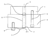
図1は本発明に関わる位置決め機構の使用態様を示す要部断面図である。
図1において、1は変動部、2は位置決めピン、3は標準部である。
位置決めピン2は、四角柱形状の角ピンであり、その対向する二側面の先端部にテーパー2aが設けられている。また、変動部1には、前記テーパー2aがある一定の深さまで挿入される四角形の開口部を有する位置決め穴4が、標準部3には、位置決めピン2が貫通する位置決め穴5が設けられている。さらに、標準部3の変動部1との接触面と反対側の面には、ボルト6により板バネ7が位置決めピン2の後端部2bを付勢するように固定されている。また、8は変動部1と標準部3が位置決めされた後、両金型同士を固定するための固定ボルトである。Embodiments of the present invention will be described below with reference to the accompanying drawings.
1 to 6 show a mold positioning mechanism as an embodiment of the present invention and its usage.
FIG. 1 is a cross-sectional view of an essential part showing a usage mode of a positioning mechanism according to the present invention.
In FIG. 1, 1 is a fluctuation | variation part, 2 is a positioning pin, 3 is a standard part.
The
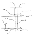
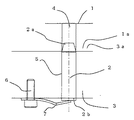
図2乃至図4は金型パーツの変動部と標準部が位置決めピンにより位置決めされる過程を示す図であり、図2は変動部が標準部に位置決めピンによりセット状態された状態、図3は変動部が標準部に位置決めピンによりセンタリングされた状態、図4は変動部が標準部に位置決めピンにより固定された状態をそれぞれ示す。
まず、図2に示すように、位置決めピン2の先端部のテーパー2aが変動部1の位置決め穴4に挿入され始める。この状態では、変動部1の標準部3との接触面1aと、標準部3の変動部1との接触面3aとは離間している。
次に、図3に示すように、変動部1を標準部3側に降下させて接触面1aと接触面3aとの距離を狭めていくと、位置決めピン2の先端部のテーパー2aにより位置決め穴4と位置決めピン2とはセンタリングされる。しかしながら、まだこの状態でも接触面1aと接触面3aとは僅かに離間している。
更に、図4に示すように、図1に示す固定ボルト8を締め付けることにより、変動部1の接触面1aと標準部3の接触面3aが接触し、位置決めピン2は位置決め穴4とのセンタリングを保ったまま、板バネ7の付勢力に抗して押し下げられ、変動部1と標準部3とが位置決め固定される。FIGS. 2 to 4 are views showing a process in which the variation part and the standard part of the mold part are positioned by the positioning pin, FIG. 2 is a state in which the variation part is set to the standard part by the positioning pin, and FIG. FIG. 4 shows a state in which the variable part is centered on the standard part by the positioning pin, and FIG. 4 shows a state in which the variable part is fixed to the standard part by the positioning pin.
First, as shown in FIG. 2, the taper 2 a at the tip of the
Next, as shown in FIG. 3, when the distance between the contact surface 1a and the
Further, as shown in FIG. 4, by tightening the
つまり、上記のような本発明の位置決め方法によれば、標準部3から突き出た角ピン状の位置決めピン2を変動部1に設けられた角穴上の位置決め穴4に挿入するだけで、位置決めピン2の先端部に加工したテーパー2aが位置決め穴4のエッジ部に滑り込み、標準部3と変動部1が自動的に位置決めされる。そして、その位置決めされた状態で、標準部3と変動部1を固定ボルト8等で締めれば両者の固定は完了する。この方法を使えば、従来のように丸ピン状の位置決めピンを圧入しないで位置決めすることができるため、位置決めピンを打ち込む必要もなく、軽い力で精度よく位置決めすることができる。
さらに、位置決めピン圧入時の大きな摩擦もないため、金型の繰り返し使用における精度も高く保つことができる。That is, according to the positioning method of the present invention as described above, the positioning can be performed simply by inserting the square pin-
Further, since there is no large friction when the positioning pin is pressed, the precision in repeated use of the mold can be kept high.
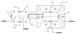
図5は本発明に関わる金型パーツの変動部1と標準部3の平面図を示す。
図5において、変動部1には、先端部にテーパーを有する四角柱状の複数の位置決めピンが挿入される、開口部が長方形の位置決め穴4a、位置決め穴4b、位置決め穴4c、及び位置決め穴4dが各辺中央部に形成されている。ここで、位置決め穴4aと位置決め穴4bとは基準線l上の対向する位置で、かつ基準線l上に開口部の長手方向がくるように配置されている。また、位置決め穴4cと位置決め穴4dとは基準線lと直交する基準線m上の対向する位置で、かつ基準線m上に開口部の長手方向がくるように配置されている。
同様に、標準部3には、先端部にテーパーを有する四角柱状の4本の位置決めピンが貫通する、開口部が長方形の位置決め穴5a、位置決め穴5b、位置決め穴5c及び位置決め穴5dが各辺中央部に形成されている。ここで、位置決め穴5aと位置決め穴5bとは基準線l上の対向する位置で、かつ基準線l上に開口部の長手方向がくるように配置されている。また、位置決め穴5cと位置決め穴5dとは基準線lと直交する基準線m上の対向する位置で、かつ基準線m上に開口部の長手方向がくるように配置されている。
よって、変動部1を標準部3上部の所望の位置にセットした後、標準部3の底面側(図5の紙面の裏側)から4本の位置決めピンを位置決め穴5a、位置決め穴5b、位置決め穴5c及び位置決め穴5dにそれぞれ貫通させ、変動部1の底面側(図5の紙面の裏側)から、対応する位置決め穴4a、位置決め穴4b、位置決め穴4c及び位置決め穴4dに挿入し、位置決めピンの先端部のテーパーにより、変動部1は標準部3に対して位置決めされる。
ここで、基準線l上の位置決めピンのテーパー形成面と基準線m上の位置決めピンのテーパー形成面が直交するため、平面内での確実な位置決めが可能となる。FIG. 5 shows a plan view of the
In FIG. 5, the
Similarly, the
Therefore, after setting the
Here, since the taper forming surface of the positioning pin on the
図6は本発明における金型位置決め機構の他の実施例を示す。図1乃至図5と同等の部材については同一の番号を付し、詳しい説明は省略する。
図6において、位置決めピン2により変動部1は標準部3に位置決めされるのであるが、位置決めピン2の後端部2bを付勢するバネはコイルバネ9を使用している。
また、変動部1を標準部3に位置決めした後、変動部1を標準部として、別の変動部11を先端部にテーパー12aを有する位置決めピン12により位置決めしている。この場合も位置決めピン12の後端部をコイルバネ19により付勢している。ここで、14は変動部11に設けられた位置決め穴、15は変動部1に設けられた位置決め穴である。FIG. 6 shows another embodiment of the mold positioning mechanism in the present invention. The same members as those in FIGS. 1 to 5 are denoted by the same reference numerals, and detailed description thereof is omitted.
In FIG. 6, the
Further, after positioning the
1 変動部
2 位置決めピン
3 標準部
4 変動部の位置決め穴
5 標準部の位置決め穴
6 ボルト
7 板バネ
8 固定ボルトDESCRIPTION OF
Claims (2)
Priority Applications (1)
| Application Number | Priority Date | Filing Date | Title |
|---|---|---|---|
| JP2012125306A JP5794496B2 (en) | 2012-04-24 | 2012-04-24 | Mold positioning mechanism |
Applications Claiming Priority (1)
| Application Number | Priority Date | Filing Date | Title |
|---|---|---|---|
| JP2012125306A JP5794496B2 (en) | 2012-04-24 | 2012-04-24 | Mold positioning mechanism |
Publications (2)
| Publication Number | Publication Date |
|---|---|
| JP2013226785A true JP2013226785A (en) | 2013-11-07 |
| JP5794496B2 JP5794496B2 (en) | 2015-10-14 |
Family
ID=49674976
Family Applications (1)
| Application Number | Title | Priority Date | Filing Date |
|---|---|---|---|
| JP2012125306A Expired - Fee Related JP5794496B2 (en) | 2012-04-24 | 2012-04-24 | Mold positioning mechanism |
Country Status (1)
| Country | Link |
|---|---|
| JP (1) | JP5794496B2 (en) |
Cited By (4)
| Publication number | Priority date | Publication date | Assignee | Title |
|---|---|---|---|---|
| JP6052526B1 (en) * | 2015-10-09 | 2016-12-27 | 株式会社Ihi | Fiber reinforced composite material molding equipment |
| CN107584732A (en) * | 2017-10-16 | 2018-01-16 | 广东长盈精密技术有限公司 | Mould bullet needle construction and bullet pin hole processing method |
| KR101853200B1 (en) * | 2016-10-20 | 2018-06-04 | 방건경 | A finishing device with auto-positioning jig |
| KR102322848B1 (en) * | 2020-07-17 | 2021-11-04 | 오충근 | Centering methods of the mold-sets of the vertical type injection molding machine |
Citations (1)
| Publication number | Priority date | Publication date | Assignee | Title |
|---|---|---|---|---|
| JPH0515534B2 (en) * | 1985-04-11 | 1993-03-01 | Nissei Plastics Ind Co |
-
2012
- 2012-04-24 JP JP2012125306A patent/JP5794496B2/en not_active Expired - Fee Related
Patent Citations (1)
| Publication number | Priority date | Publication date | Assignee | Title |
|---|---|---|---|---|
| JPH0515534B2 (en) * | 1985-04-11 | 1993-03-01 | Nissei Plastics Ind Co |
Cited By (5)
| Publication number | Priority date | Publication date | Assignee | Title |
|---|---|---|---|---|
| JP6052526B1 (en) * | 2015-10-09 | 2016-12-27 | 株式会社Ihi | Fiber reinforced composite material molding equipment |
| WO2017061047A1 (en) * | 2015-10-09 | 2017-04-13 | 株式会社Ihi | Fiber-reinforced composite member forming device |
| KR101853200B1 (en) * | 2016-10-20 | 2018-06-04 | 방건경 | A finishing device with auto-positioning jig |
| CN107584732A (en) * | 2017-10-16 | 2018-01-16 | 广东长盈精密技术有限公司 | Mould bullet needle construction and bullet pin hole processing method |
| KR102322848B1 (en) * | 2020-07-17 | 2021-11-04 | 오충근 | Centering methods of the mold-sets of the vertical type injection molding machine |
Also Published As
| Publication number | Publication date |
|---|---|
| JP5794496B2 (en) | 2015-10-14 |
Similar Documents
| Publication | Publication Date | Title |
|---|---|---|
| US8998281B2 (en) | Clamping mechanism | |
| JP5794496B2 (en) | Mold positioning mechanism | |
| JP6041189B2 (en) | Snap ring mounting jig | |
| US7699298B2 (en) | Jig for holding a core and method utilizing the same | |
| US20130207332A1 (en) | Adjustment mechanism | |
| JP2014091066A (en) | Vibration generation system and manufacturing method of the same | |
| JP2014107924A (en) | Ipm rotor structure | |
| JP5485806B2 (en) | Mold positioning and fixing device | |
| JP2005103639A (en) | Apparatus for supporting pilot punch | |
| JP5721689B2 (en) | Manufacturing method of spirit level | |
| CN104338852B (en) | A kind of mould | |
| TWM511948U (en) | Press mechanism | |
| JP2017010803A (en) | Connector insertion jig | |
| JP5069616B2 (en) | magnet catch | |
| JP2011025430A (en) | Mold and method for positionally adjusting the same | |
| JP6247085B2 (en) | Mold | |
| JP2016223098A (en) | Panel frame | |
| JP6163085B2 (en) | Pallet for parts alignment and manufacturing method thereof | |
| KR101815201B1 (en) | Cam Slide Unit | |
| KR101619289B1 (en) | Positioning plate for chucks | |
| JP4635640B2 (en) | Optical component fixing ferrule mold and mold adjustment method | |
| CN204700168U (en) | The split type die sleeve of a kind of straight die shank | |
| JP2012045597A (en) | Punch die | |
| JP6012699B2 (en) | Board stopper | |
| JP2016128179A (en) | Plate material stock device |
Legal Events
| Date | Code | Title | Description |
|---|---|---|---|
| A871 | Explanation of circumstances concerning accelerated examination |
Free format text: JAPANESE INTERMEDIATE CODE: A871 Effective date: 20140922 |
|
| A621 | Written request for application examination |
Free format text: JAPANESE INTERMEDIATE CODE: A621 Effective date: 20140922 |
|
| A521 | Written amendment |
Free format text: JAPANESE INTERMEDIATE CODE: A523 Effective date: 20141104 |
|
| A975 | Report on accelerated examination |
Free format text: JAPANESE INTERMEDIATE CODE: A971005 Effective date: 20141210 |
|
| A131 | Notification of reasons for refusal |
Free format text: JAPANESE INTERMEDIATE CODE: A131 Effective date: 20150106 |
|
| A521 | Written amendment |
Free format text: JAPANESE INTERMEDIATE CODE: A523 Effective date: 20150304 |
|
| A131 | Notification of reasons for refusal |
Free format text: JAPANESE INTERMEDIATE CODE: A131 Effective date: 20150512 |
|
| A521 | Written amendment |
Free format text: JAPANESE INTERMEDIATE CODE: A523 Effective date: 20150603 |
|
| TRDD | Decision of grant or rejection written | ||
| A01 | Written decision to grant a patent or to grant a registration (utility model) |
Free format text: JAPANESE INTERMEDIATE CODE: A01 Effective date: 20150721 |
|
| A61 | First payment of annual fees (during grant procedure) |
Free format text: JAPANESE INTERMEDIATE CODE: A61 Effective date: 20150801 |
|
| R150 | Certificate of patent or registration of utility model |
Ref document number: 5794496 Country of ref document: JP Free format text: JAPANESE INTERMEDIATE CODE: R150 |
|
| LAPS | Cancellation because of no payment of annual fees |


