JP2005009495A - Indirect injection internal combustion supercharged engine in which combustion gas is scavenged, and method of supplying supercharged air to the engine - Google Patents
Indirect injection internal combustion supercharged engine in which combustion gas is scavenged, and method of supplying supercharged air to the engine Download PDFInfo
- Publication number
- JP2005009495A JP2005009495A JP2004179473A JP2004179473A JP2005009495A JP 2005009495 A JP2005009495 A JP 2005009495A JP 2004179473 A JP2004179473 A JP 2004179473A JP 2004179473 A JP2004179473 A JP 2004179473A JP 2005009495 A JP2005009495 A JP 2005009495A
- Authority
- JP
- Japan
- Prior art keywords
- intake
- supercharged
- air
- supercharged air
- engine
- Prior art date
- Legal status (The legal status is an assumption and is not a legal conclusion. Google has not performed a legal analysis and makes no representation as to the accuracy of the status listed.)
- Granted
Links
- 238000002347 injection Methods 0.000 title claims abstract description 47
- 239000007924 injection Substances 0.000 title claims abstract description 47
- 238000002485 combustion reaction Methods 0.000 title claims abstract description 26
- 238000000034 method Methods 0.000 title claims description 8
- 239000000567 combustion gas Substances 0.000 title description 14
- 239000000446 fuel Substances 0.000 claims abstract description 39
- 238000005192 partition Methods 0.000 claims description 15
- 230000000694 effects Effects 0.000 abstract description 3
- 239000000243 solution Substances 0.000 abstract 1
- 230000002000 scavenging effect Effects 0.000 description 41
- 230000004087 circulation Effects 0.000 description 4
- 238000012986 modification Methods 0.000 description 3
- 230000004048 modification Effects 0.000 description 3
- 230000006835 compression Effects 0.000 description 2
- 238000007906 compression Methods 0.000 description 2
- 229930195733 hydrocarbon Natural products 0.000 description 1
- 150000002430 hydrocarbons Chemical class 0.000 description 1
- 239000000203 mixture Substances 0.000 description 1
Images
Classifications
-
- F—MECHANICAL ENGINEERING; LIGHTING; HEATING; WEAPONS; BLASTING
- F02—COMBUSTION ENGINES; HOT-GAS OR COMBUSTION-PRODUCT ENGINE PLANTS
- F02M—SUPPLYING COMBUSTION ENGINES IN GENERAL WITH COMBUSTIBLE MIXTURES OR CONSTITUENTS THEREOF
- F02M35/00—Combustion-air cleaners, air intakes, intake silencers, or induction systems specially adapted for, or arranged on, internal-combustion engines
- F02M35/10—Air intakes; Induction systems
- F02M35/104—Intake manifolds
- F02M35/108—Intake manifolds with primary and secondary intake passages
-
- F—MECHANICAL ENGINEERING; LIGHTING; HEATING; WEAPONS; BLASTING
- F02—COMBUSTION ENGINES; HOT-GAS OR COMBUSTION-PRODUCT ENGINE PLANTS
- F02B—INTERNAL-COMBUSTION PISTON ENGINES; COMBUSTION ENGINES IN GENERAL
- F02B17/00—Engines characterised by means for effecting stratification of charge in cylinders
-
- F—MECHANICAL ENGINEERING; LIGHTING; HEATING; WEAPONS; BLASTING
- F02—COMBUSTION ENGINES; HOT-GAS OR COMBUSTION-PRODUCT ENGINE PLANTS
- F02B—INTERNAL-COMBUSTION PISTON ENGINES; COMBUSTION ENGINES IN GENERAL
- F02B25/00—Engines characterised by using fresh charge for scavenging cylinders
- F02B25/02—Engines characterised by using fresh charge for scavenging cylinders using unidirectional scavenging
- F02B25/04—Engines having ports both in cylinder head and in cylinder wall near bottom of piston stroke
-
- F—MECHANICAL ENGINEERING; LIGHTING; HEATING; WEAPONS; BLASTING
- F02—COMBUSTION ENGINES; HOT-GAS OR COMBUSTION-PRODUCT ENGINE PLANTS
- F02B—INTERNAL-COMBUSTION PISTON ENGINES; COMBUSTION ENGINES IN GENERAL
- F02B27/00—Use of kinetic or wave energy of charge in induction systems, or of combustion residues in exhaust systems, for improving quantity of charge or for increasing removal of combustion residues
- F02B27/02—Use of kinetic or wave energy of charge in induction systems, or of combustion residues in exhaust systems, for improving quantity of charge or for increasing removal of combustion residues the systems having variable, i.e. adjustable, cross-sectional areas, chambers of variable volume, or like variable means
- F02B27/0205—Use of kinetic or wave energy of charge in induction systems, or of combustion residues in exhaust systems, for improving quantity of charge or for increasing removal of combustion residues the systems having variable, i.e. adjustable, cross-sectional areas, chambers of variable volume, or like variable means characterised by the charging effect
- F02B27/021—Resonance charging
-
- F—MECHANICAL ENGINEERING; LIGHTING; HEATING; WEAPONS; BLASTING
- F02—COMBUSTION ENGINES; HOT-GAS OR COMBUSTION-PRODUCT ENGINE PLANTS
- F02B—INTERNAL-COMBUSTION PISTON ENGINES; COMBUSTION ENGINES IN GENERAL
- F02B27/00—Use of kinetic or wave energy of charge in induction systems, or of combustion residues in exhaust systems, for improving quantity of charge or for increasing removal of combustion residues
- F02B27/02—Use of kinetic or wave energy of charge in induction systems, or of combustion residues in exhaust systems, for improving quantity of charge or for increasing removal of combustion residues the systems having variable, i.e. adjustable, cross-sectional areas, chambers of variable volume, or like variable means
- F02B27/0226—Use of kinetic or wave energy of charge in induction systems, or of combustion residues in exhaust systems, for improving quantity of charge or for increasing removal of combustion residues the systems having variable, i.e. adjustable, cross-sectional areas, chambers of variable volume, or like variable means characterised by the means generating the charging effect
- F02B27/0242—Fluid communication passages between intake ducts, runners or chambers
-
- F—MECHANICAL ENGINEERING; LIGHTING; HEATING; WEAPONS; BLASTING
- F02—COMBUSTION ENGINES; HOT-GAS OR COMBUSTION-PRODUCT ENGINE PLANTS
- F02B—INTERNAL-COMBUSTION PISTON ENGINES; COMBUSTION ENGINES IN GENERAL
- F02B27/00—Use of kinetic or wave energy of charge in induction systems, or of combustion residues in exhaust systems, for improving quantity of charge or for increasing removal of combustion residues
- F02B27/02—Use of kinetic or wave energy of charge in induction systems, or of combustion residues in exhaust systems, for improving quantity of charge or for increasing removal of combustion residues the systems having variable, i.e. adjustable, cross-sectional areas, chambers of variable volume, or like variable means
- F02B27/0226—Use of kinetic or wave energy of charge in induction systems, or of combustion residues in exhaust systems, for improving quantity of charge or for increasing removal of combustion residues the systems having variable, i.e. adjustable, cross-sectional areas, chambers of variable volume, or like variable means characterised by the means generating the charging effect
- F02B27/0247—Plenum chambers; Resonance chambers or resonance pipes
- F02B27/0252—Multiple plenum chambers or plenum chambers having inner separation walls, e.g. comprising valves for the same group of cylinders
-
- F—MECHANICAL ENGINEERING; LIGHTING; HEATING; WEAPONS; BLASTING
- F02—COMBUSTION ENGINES; HOT-GAS OR COMBUSTION-PRODUCT ENGINE PLANTS
- F02B—INTERNAL-COMBUSTION PISTON ENGINES; COMBUSTION ENGINES IN GENERAL
- F02B27/00—Use of kinetic or wave energy of charge in induction systems, or of combustion residues in exhaust systems, for improving quantity of charge or for increasing removal of combustion residues
- F02B27/02—Use of kinetic or wave energy of charge in induction systems, or of combustion residues in exhaust systems, for improving quantity of charge or for increasing removal of combustion residues the systems having variable, i.e. adjustable, cross-sectional areas, chambers of variable volume, or like variable means
- F02B27/0226—Use of kinetic or wave energy of charge in induction systems, or of combustion residues in exhaust systems, for improving quantity of charge or for increasing removal of combustion residues the systems having variable, i.e. adjustable, cross-sectional areas, chambers of variable volume, or like variable means characterised by the means generating the charging effect
- F02B27/0289—Intake runners having multiple intake valves per cylinder
-
- F—MECHANICAL ENGINEERING; LIGHTING; HEATING; WEAPONS; BLASTING
- F02—COMBUSTION ENGINES; HOT-GAS OR COMBUSTION-PRODUCT ENGINE PLANTS
- F02B—INTERNAL-COMBUSTION PISTON ENGINES; COMBUSTION ENGINES IN GENERAL
- F02B31/00—Modifying induction systems for imparting a rotation to the charge in the cylinder
- F02B31/08—Modifying induction systems for imparting a rotation to the charge in the cylinder having multiple air inlets
- F02B31/085—Modifying induction systems for imparting a rotation to the charge in the cylinder having multiple air inlets having two inlet valves
-
- F—MECHANICAL ENGINEERING; LIGHTING; HEATING; WEAPONS; BLASTING
- F02—COMBUSTION ENGINES; HOT-GAS OR COMBUSTION-PRODUCT ENGINE PLANTS
- F02B—INTERNAL-COMBUSTION PISTON ENGINES; COMBUSTION ENGINES IN GENERAL
- F02B33/00—Engines characterised by provision of pumps for charging or scavenging
- F02B33/44—Passages conducting the charge from the pump to the engine inlet, e.g. reservoirs
-
- F—MECHANICAL ENGINEERING; LIGHTING; HEATING; WEAPONS; BLASTING
- F02—COMBUSTION ENGINES; HOT-GAS OR COMBUSTION-PRODUCT ENGINE PLANTS
- F02B—INTERNAL-COMBUSTION PISTON ENGINES; COMBUSTION ENGINES IN GENERAL
- F02B75/00—Other engines
- F02B75/16—Engines characterised by number of cylinders, e.g. single-cylinder engines
- F02B75/18—Multi-cylinder engines
- F02B75/20—Multi-cylinder engines with cylinders all in one line
-
- F—MECHANICAL ENGINEERING; LIGHTING; HEATING; WEAPONS; BLASTING
- F02—COMBUSTION ENGINES; HOT-GAS OR COMBUSTION-PRODUCT ENGINE PLANTS
- F02D—CONTROLLING COMBUSTION ENGINES
- F02D9/00—Controlling engines by throttling air or fuel-and-air induction conduits or exhaust conduits
- F02D9/08—Throttle valves specially adapted therefor; Arrangements of such valves in conduits
- F02D9/10—Throttle valves specially adapted therefor; Arrangements of such valves in conduits having pivotally-mounted flaps
- F02D9/109—Throttle valves specially adapted therefor; Arrangements of such valves in conduits having pivotally-mounted flaps having two or more flaps
- F02D9/1095—Rotating on a common axis, e.g. having a common shaft
-
- F—MECHANICAL ENGINEERING; LIGHTING; HEATING; WEAPONS; BLASTING
- F02—COMBUSTION ENGINES; HOT-GAS OR COMBUSTION-PRODUCT ENGINE PLANTS
- F02F—CYLINDERS, PISTONS OR CASINGS, FOR COMBUSTION ENGINES; ARRANGEMENTS OF SEALINGS IN COMBUSTION ENGINES
- F02F1/00—Cylinders; Cylinder heads
- F02F1/24—Cylinder heads
- F02F1/42—Shape or arrangement of intake or exhaust channels in cylinder heads
- F02F1/4214—Shape or arrangement of intake or exhaust channels in cylinder heads specially adapted for four or more valves per cylinder
-
- F—MECHANICAL ENGINEERING; LIGHTING; HEATING; WEAPONS; BLASTING
- F02—COMBUSTION ENGINES; HOT-GAS OR COMBUSTION-PRODUCT ENGINE PLANTS
- F02M—SUPPLYING COMBUSTION ENGINES IN GENERAL WITH COMBUSTIBLE MIXTURES OR CONSTITUENTS THEREOF
- F02M35/00—Combustion-air cleaners, air intakes, intake silencers, or induction systems specially adapted for, or arranged on, internal-combustion engines
- F02M35/10—Air intakes; Induction systems
- F02M35/10006—Air intakes; Induction systems characterised by the position of elements of the air intake system in direction of the air intake flow, i.e. between ambient air inlet and supply to the combustion chamber
- F02M35/10026—Plenum chambers
- F02M35/10032—Plenum chambers specially shaped or arranged connecting duct between carburettor or air inlet duct and the plenum chamber; specially positioned carburettors or throttle bodies with respect to the plenum chamber
-
- F—MECHANICAL ENGINEERING; LIGHTING; HEATING; WEAPONS; BLASTING
- F02—COMBUSTION ENGINES; HOT-GAS OR COMBUSTION-PRODUCT ENGINE PLANTS
- F02M—SUPPLYING COMBUSTION ENGINES IN GENERAL WITH COMBUSTIBLE MIXTURES OR CONSTITUENTS THEREOF
- F02M35/00—Combustion-air cleaners, air intakes, intake silencers, or induction systems specially adapted for, or arranged on, internal-combustion engines
- F02M35/10—Air intakes; Induction systems
- F02M35/10006—Air intakes; Induction systems characterised by the position of elements of the air intake system in direction of the air intake flow, i.e. between ambient air inlet and supply to the combustion chamber
- F02M35/10026—Plenum chambers
- F02M35/10045—Multiple plenum chambers; Plenum chambers having inner separation walls
-
- F—MECHANICAL ENGINEERING; LIGHTING; HEATING; WEAPONS; BLASTING
- F02—COMBUSTION ENGINES; HOT-GAS OR COMBUSTION-PRODUCT ENGINE PLANTS
- F02M—SUPPLYING COMBUSTION ENGINES IN GENERAL WITH COMBUSTIBLE MIXTURES OR CONSTITUENTS THEREOF
- F02M35/00—Combustion-air cleaners, air intakes, intake silencers, or induction systems specially adapted for, or arranged on, internal-combustion engines
- F02M35/10—Air intakes; Induction systems
- F02M35/10006—Air intakes; Induction systems characterised by the position of elements of the air intake system in direction of the air intake flow, i.e. between ambient air inlet and supply to the combustion chamber
- F02M35/10026—Plenum chambers
- F02M35/10065—Valves arranged in the plenum chamber
-
- F—MECHANICAL ENGINEERING; LIGHTING; HEATING; WEAPONS; BLASTING
- F02—COMBUSTION ENGINES; HOT-GAS OR COMBUSTION-PRODUCT ENGINE PLANTS
- F02M—SUPPLYING COMBUSTION ENGINES IN GENERAL WITH COMBUSTIBLE MIXTURES OR CONSTITUENTS THEREOF
- F02M35/00—Combustion-air cleaners, air intakes, intake silencers, or induction systems specially adapted for, or arranged on, internal-combustion engines
- F02M35/10—Air intakes; Induction systems
- F02M35/1015—Air intakes; Induction systems characterised by the engine type
- F02M35/10157—Supercharged engines
-
- F—MECHANICAL ENGINEERING; LIGHTING; HEATING; WEAPONS; BLASTING
- F02—COMBUSTION ENGINES; HOT-GAS OR COMBUSTION-PRODUCT ENGINE PLANTS
- F02M—SUPPLYING COMBUSTION ENGINES IN GENERAL WITH COMBUSTIBLE MIXTURES OR CONSTITUENTS THEREOF
- F02M35/00—Combustion-air cleaners, air intakes, intake silencers, or induction systems specially adapted for, or arranged on, internal-combustion engines
- F02M35/10—Air intakes; Induction systems
- F02M35/1015—Air intakes; Induction systems characterised by the engine type
- F02M35/1019—Two-stroke engines; Reverse-flow scavenged or cross scavenged engines
-
- F—MECHANICAL ENGINEERING; LIGHTING; HEATING; WEAPONS; BLASTING
- F02—COMBUSTION ENGINES; HOT-GAS OR COMBUSTION-PRODUCT ENGINE PLANTS
- F02M—SUPPLYING COMBUSTION ENGINES IN GENERAL WITH COMBUSTIBLE MIXTURES OR CONSTITUENTS THEREOF
- F02M35/00—Combustion-air cleaners, air intakes, intake silencers, or induction systems specially adapted for, or arranged on, internal-combustion engines
- F02M35/10—Air intakes; Induction systems
- F02M35/10209—Fluid connections to the air intake system; their arrangement of pipes, valves or the like
- F02M35/10222—Exhaust gas recirculation [EGR]; Positive crankcase ventilation [PCV]; Additional air admission, lubricant or fuel vapour admission
-
- F—MECHANICAL ENGINEERING; LIGHTING; HEATING; WEAPONS; BLASTING
- F02—COMBUSTION ENGINES; HOT-GAS OR COMBUSTION-PRODUCT ENGINE PLANTS
- F02M—SUPPLYING COMBUSTION ENGINES IN GENERAL WITH COMBUSTIBLE MIXTURES OR CONSTITUENTS THEREOF
- F02M35/00—Combustion-air cleaners, air intakes, intake silencers, or induction systems specially adapted for, or arranged on, internal-combustion engines
- F02M35/10—Air intakes; Induction systems
- F02M35/104—Intake manifolds
- F02M35/108—Intake manifolds with primary and secondary intake passages
- F02M35/1085—Intake manifolds with primary and secondary intake passages the combustion chamber having multiple intake valves
-
- F—MECHANICAL ENGINEERING; LIGHTING; HEATING; WEAPONS; BLASTING
- F02—COMBUSTION ENGINES; HOT-GAS OR COMBUSTION-PRODUCT ENGINE PLANTS
- F02B—INTERNAL-COMBUSTION PISTON ENGINES; COMBUSTION ENGINES IN GENERAL
- F02B75/00—Other engines
- F02B75/16—Engines characterised by number of cylinders, e.g. single-cylinder engines
- F02B75/18—Multi-cylinder engines
- F02B2075/1804—Number of cylinders
- F02B2075/1816—Number of cylinders four
-
- F—MECHANICAL ENGINEERING; LIGHTING; HEATING; WEAPONS; BLASTING
- F02—COMBUSTION ENGINES; HOT-GAS OR COMBUSTION-PRODUCT ENGINE PLANTS
- F02B—INTERNAL-COMBUSTION PISTON ENGINES; COMBUSTION ENGINES IN GENERAL
- F02B2275/00—Other engines, components or details, not provided for in other groups of this subclass
- F02B2275/16—Indirect injection
-
- F—MECHANICAL ENGINEERING; LIGHTING; HEATING; WEAPONS; BLASTING
- F02—COMBUSTION ENGINES; HOT-GAS OR COMBUSTION-PRODUCT ENGINE PLANTS
- F02M—SUPPLYING COMBUSTION ENGINES IN GENERAL WITH COMBUSTIBLE MIXTURES OR CONSTITUENTS THEREOF
- F02M26/00—Engine-pertinent apparatus for adding exhaust gases to combustion-air, main fuel or fuel-air mixture, e.g. by exhaust gas recirculation [EGR] systems
- F02M2026/001—Arrangements; Control features; Details
- F02M2026/009—EGR combined with means to change air/fuel ratio, ignition timing, charge swirl in the cylinder
-
- F—MECHANICAL ENGINEERING; LIGHTING; HEATING; WEAPONS; BLASTING
- F02—COMBUSTION ENGINES; HOT-GAS OR COMBUSTION-PRODUCT ENGINE PLANTS
- F02M—SUPPLYING COMBUSTION ENGINES IN GENERAL WITH COMBUSTIBLE MIXTURES OR CONSTITUENTS THEREOF
- F02M35/00—Combustion-air cleaners, air intakes, intake silencers, or induction systems specially adapted for, or arranged on, internal-combustion engines
- F02M35/10—Air intakes; Induction systems
- F02M35/10209—Fluid connections to the air intake system; their arrangement of pipes, valves or the like
- F02M35/10216—Fuel injectors; Fuel pipes or rails; Fuel pumps or pressure regulators
-
- F—MECHANICAL ENGINEERING; LIGHTING; HEATING; WEAPONS; BLASTING
- F02—COMBUSTION ENGINES; HOT-GAS OR COMBUSTION-PRODUCT ENGINE PLANTS
- F02M—SUPPLYING COMBUSTION ENGINES IN GENERAL WITH COMBUSTIBLE MIXTURES OR CONSTITUENTS THEREOF
- F02M35/00—Combustion-air cleaners, air intakes, intake silencers, or induction systems specially adapted for, or arranged on, internal-combustion engines
- F02M35/10—Air intakes; Induction systems
- F02M35/104—Intake manifolds
- F02M35/112—Intake manifolds for engines with cylinders all in one line
-
- Y—GENERAL TAGGING OF NEW TECHNOLOGICAL DEVELOPMENTS; GENERAL TAGGING OF CROSS-SECTIONAL TECHNOLOGIES SPANNING OVER SEVERAL SECTIONS OF THE IPC; TECHNICAL SUBJECTS COVERED BY FORMER USPC CROSS-REFERENCE ART COLLECTIONS [XRACs] AND DIGESTS
- Y02—TECHNOLOGIES OR APPLICATIONS FOR MITIGATION OR ADAPTATION AGAINST CLIMATE CHANGE
- Y02T—CLIMATE CHANGE MITIGATION TECHNOLOGIES RELATED TO TRANSPORTATION
- Y02T10/00—Road transport of goods or passengers
- Y02T10/10—Internal combustion engine [ICE] based vehicles
- Y02T10/12—Improving ICE efficiencies
Landscapes
- Engineering & Computer Science (AREA)
- Chemical & Material Sciences (AREA)
- Combustion & Propulsion (AREA)
- Mechanical Engineering (AREA)
- General Engineering & Computer Science (AREA)
- Supercharger (AREA)
- Characterised By The Charging Evacuation (AREA)
Abstract
Description
本発明は、特に間接噴射の過給式内燃エンジン、およびそのようなエンジンへの供給方法に関する。 The invention relates in particular to a supercharged internal combustion engine with indirect injection and a supply method for such an engine.
本発明は、より詳しくは、吸気行程において燃焼ガスを掃気する過給式エンジンへの給気手段に関する。 More particularly, the present invention relates to an air supply means for a supercharged engine that scavenges combustion gas in an intake stroke.
周知のように、エンジンが発生する出力は、燃焼室内に供給される空気の量によって決まる。この出力を増大させるために、エンジンの燃焼室内に供給される前に圧縮された吸気が用いられる。この空気は、一般に過給気と呼ばれており、ターボ過給機などの任意の公知の手段によって圧縮されている。 As is well known, the power generated by the engine depends on the amount of air supplied into the combustion chamber. In order to increase this output, intake air that has been compressed before being fed into the combustion chamber of the engine is used. This air is generally called supercharged air and is compressed by any known means such as a turbocharger.
本願の出願人によって出願されている特許文献1に既に記載されているように、直接噴射の過給式エンジンの出力は、燃焼室内に供給される過給気の量を増やすことによって、さらに増大させることが可能である。したがって、燃焼室内に含まれる残留燃焼ガスは、このエンジンの吸気行程の開始時に排出され、過給気に置き換えられる。この動作は、燃焼ガスの掃気と呼ばれ、排気弁と吸気弁とのオーバーラップによって実現される。この動作の終了時にも、吸気行程は継続し、排気弁が閉じると、燃料が燃焼室内に噴射される。 As already described in U.S. Pat. No. 6,057,097 filed by the applicant of this application, the output of a direct injection supercharged engine is further increased by increasing the amount of supercharged air supplied into the combustion chamber. It is possible to make it. Therefore, the residual combustion gas contained in the combustion chamber is discharged at the start of the intake stroke of the engine and is replaced with supercharged air. This operation is called scavenging of combustion gas, and is realized by the overlap between the exhaust valve and the intake valve. At the end of this operation, the intake stroke continues, and when the exhaust valve is closed, fuel is injected into the combustion chamber.
2002年6月21日に出願されている仏国特許出願第02/07,693号明細書の中でより詳細に説明されているように、出願人は間接噴射の過給式エンジンの構成内にこの構成を設けている。 As described in more detail in French Patent Application No. 02 / 07,693 filed on June 21, 2002, the applicant is in the form of a supercharged engine with indirect injection. This configuration is provided.
燃焼ガスの掃気動作は、実質的には管と弁とからなる、燃料が混合されていない過給気用の特別な吸気手段を追加することによって、このエンジン内で行われるようになっている。したがって、このエンジンは、燃料が混合されていない過給気が掃気動作中に燃焼室内に流入することを可能にする第1の吸気手段と、第1の吸気手段が閉じたときに、燃料が混合されている過給気が燃焼室内に流入することを可能にする第2の吸気手段とを有している。したがって、燃焼ガスの掃気動作は、エンジンの吸気行程の開始時に、排気弁と燃料が混合されていない過給気用の吸気弁とによって行われるようになっている。このオーバーラップ中は、排気弁は開いたままであり、燃料が混合されていない過給気は第1の吸気手段を介して燃焼室内に流入することができる。したがって、残留燃焼ガスは、燃料が混合されていない過給気に置き換えられる。掃気動作の終了時に、排気弁が閉じ、燃料を含んだ過給気は、マルチポイント燃料インジェクションの場合には燃料インジェクタを備えている他の吸気手段を介して燃焼室内に流入することができる。 The scavenging operation of the combustion gas is carried out in this engine by adding a special intake means for supercharged air, which is essentially a tube and a valve and is not mixed with fuel. . Therefore, the engine has a first intake means that allows supercharged air that is not mixed with fuel to flow into the combustion chamber during the scavenging operation, and the fuel is discharged when the first intake means is closed. And a second intake means for allowing the mixed supercharged air to flow into the combustion chamber. Therefore, the scavenging operation of the combustion gas is performed at the start of the intake stroke of the engine by the exhaust valve and the supercharged intake valve in which fuel is not mixed. During this overlap, the exhaust valve remains open, and the supercharged air that is not mixed with fuel can flow into the combustion chamber via the first intake means. Therefore, the residual combustion gas is replaced with supercharged air that is not mixed with fuel. At the end of the scavenging operation, the exhaust valve is closed, and the supercharged air containing fuel can flow into the combustion chamber via other intake means equipped with a fuel injector in the case of multipoint fuel injection.
一般に、吸気管の自由端は、過給気の供給手段、通常は吸気マニフォールドに接続されており、吸気マニフォールドの入口は空気圧縮手段の出口に接続されている。
エンジンの動作中は、吸気マニフォールドに流入した過給気は、全ての吸気管に全体的に供給される。この場合、燃料が混合された過給気と燃料が混合されていない過給気用の吸気管からの過給気とが混合されるおそれがある。そのため、吸気行程の開始時に掃気動作が実行されたときには、部分的に燃料が混合された過給気が燃焼室内に供給され、それから、燃焼ガスとともに排気弁を介して排出される。 While the engine is operating, the supercharged air flowing into the intake manifold is supplied to all intake pipes as a whole. In this case, there is a possibility that the supercharged air mixed with the fuel and the supercharged air from the intake pipe for the supercharged air not mixed with the fuel may be mixed. Therefore, when the scavenging operation is executed at the start of the intake stroke, the supercharged air partially mixed with fuel is supplied into the combustion chamber, and then discharged together with the combustion gas through the exhaust valve.
このことは、燃料の消費を増大させ、未燃焼の炭化水素などが排気時に排出されることにつながる。 This increases fuel consumption and leads to unburned hydrocarbons being discharged during exhaust.
そのため、本発明は、吸気マニフォールド内の音響効果に対して有利に働きつつ、2つの吸気手段の間を燃料が迂回することを防止する、簡単な構成の過給気供給手段によって、前述の欠点を克服することを目的とする。 For this reason, the present invention provides the above-mentioned drawbacks by means of a supercharged air supply means with a simple configuration that works against acoustic effects in the intake manifold while preventing the fuel from bypassing between the two intake means. The purpose is to overcome.
したがって、本発明は、一方の種類が、燃料が混合されていない過給気の吸気手段であり、他方の種類が、燃料が混合されている過給気の吸気手段である、2種類の過給気吸気手段を備えている少なくとも1つのシリンダを有し、供給手段によって吸気手段に過給気が供給される、特に間接噴射の過給式内燃エンジンにおいて、供給手段は、吸気手段の各々の種類用の特別な過給気供給装置を有していることを特徴とする、特に間接噴射の過給式内燃エンジンに関する。 Therefore, according to the present invention, one type is a supercharging air intake means in which fuel is not mixed, and the other type is a supercharging air intake means in which fuel is mixed. In the supercharged internal combustion engine of indirect injection, in particular, the supply means has at least one cylinder provided with the intake air intake means, and the intake air is supplied to the intake means by the supply means. In particular, the invention relates to a supercharged internal combustion engine with indirect injection, characterized in that it has a special supercharger supply device for the type.
供給手段が吸気マニフォールドを有している場合、吸気マニフォールドは両過給気供給装置を画定する内部の仕切りを有していることが有利である。 If the supply means has an intake manifold, it is advantageous for the intake manifold to have an internal partition defining both supercharged air supply devices.
一方の過給気供給装置は、過給気入口と、他方の過給気供給装置との連通を可能にする手段とを有していてもよい。 One supercharged air supply device may have a supercharged air inlet and a means for enabling communication with the other supercharged air supply device.
連通手段は、両過給気供給装置を接続する管路を有していてもよい。 The communication means may have a pipe line connecting both supercharged air supply devices.
接続管路は絞り手段を備えていることが好ましい。 It is preferable that the connecting pipe has a throttle means.
連通手段は、仕切りに通路を有していてもよい。 The communication means may have a passage in the partition.
通路は逆止手段または絞り手段を有していることが好ましい。 The passage preferably has a check means or a throttle means.
供給手段は、両過給気供給装置に共通する空気入口を有していてもよい。 The supply means may have an air inlet common to both supercharged air supply devices.
空気入口は、各過給気供給装置内への吸気を制御する絞り手段を有していてもよい。 The air inlet may have throttle means for controlling intake air into each supercharged air supply device.
絞り手段はバタフライバルブであることが好ましい。 The throttling means is preferably a butterfly valve.
供給手段は、各過給気供給装置用の空気入口を有していてもよい。 The supply means may have an air inlet for each supercharged air supply device.
また、本発明は、一方の種類が、燃料が混合されていない過給気の吸気手段であり、他方の種類が、燃料が混合されている過給気の吸気手段である、2種類の過給気吸気手段を備えている少なくとも1つのシリンダを有し、供給手段によって吸気手段に過給気が供給される、特に間接噴射の過給式内燃エンジン用の過給気の供給方法において、各々の種類の吸気手段に過給気を別々に供給することを特徴とする、過給気の供給方法に関する。 In addition, the present invention provides two types of overcharge air intake means in which one type is supercharged air that is not mixed with fuel, and the other type is intake means for supercharged air that is mixed with fuel. In a supercharged air supply method for a supercharged internal combustion engine of indirect injection, which has at least one cylinder provided with a charge air intake means, and supercharged air is supplied to the intake means by the supply means. The present invention relates to a method for supplying supercharged air, characterized in that supercharged air is separately supplied to different types of intake means.
各々の種類の吸気手段に過給気を連続的に供給してもよい。 The supercharged air may be continuously supplied to each type of intake means.
各々の種類の吸気手段に過給気を同時に供給してもよい。 You may supply supercharging air simultaneously to each kind of intake means.
本発明のその他の特徴と利点は、添付図面を参照して、非限定的な例による以降の説明を読むことで明らかになるであろう。 Other features and advantages of the present invention will become apparent upon reading the following description by way of non-limiting example with reference to the accompanying drawings.
図1は、特にガソリンエンジンであって好ましくは火花点火式のエンジンである、間接噴射の過給式内燃エンジンのシリンダ10を示している。
FIG. 1 shows a
シリンダ10は、吸気管16および18と吸気弁20および22などの遮断手段とを各々が備えている、2つの種類の過給気吸気手段12および14を有している。吸気管18は燃料噴射手段24を備えているが、吸気管16は燃料噴射手段を備えていない。以下では、説明を簡略化するために、吸気管16と吸気弁20を燃料が混合されていない過給気吸気管および弁と呼び、吸気管18と吸気弁22を燃料が混合されている過給気吸気管および弁と呼ぶ。
The
このシリンダ10は、排気管28と排気弁などの遮断手段30とを備えている2つの排気手段26も有している。吸気手段と排気手段は、ピストン34の上側部分と共にこのシリンダ10の燃焼室36を画定することを可能にしているシリンダヘッド32によって支持されている。
The
吸気行程の開始時にピストン34の上死点付近にあるときに、燃焼室36内の燃焼ガスの掃気を実行するように、排気弁26と燃料が混合されていない過給気吸気弁20との間でオーバーラップが実現する。したがって、燃焼室36内に存在する燃焼ガスの圧力よりも高い圧力を有している、燃料が混合されていない過給気は、燃焼室内36を通過することが可能であり、かつ、排気弁30を介して燃焼ガスを排出させるように燃焼ガスを掃気する。排気弁30が閉じるとすぐに、燃料が混合されている過給気の吸気弁22が開き、過給気と燃料との混合気が燃焼室36内に流入できるようになる。
When the intake stroke is near the top dead center of the piston 34, the
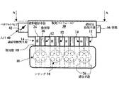
図2からわかるように、シリンダ10は、少なくとも1つのシリンダ、一般的には4つのシリンダを有し、エンジンブロック33に支持されたシリンダヘッド32を備えているエンジンの一部である。
As can be seen from FIG. 2, the
各シリンダ10の吸気管16および18の各々は、一般に吸気マニフォールドと呼ばれ、入口40によってターボ過給機などの空気圧縮手段(不図示)の出口に接続されている空気供給手段38に独立に接続されている。入口40は、この吸気マニフォールド38内に供給される過給気の量を調節可能な、たとえばバタフライバルブである絞り手段42を備えていることが有利である。
Each of the
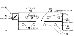
図3に示されているように、本発明の第1の実施形態では、吸気マニフォールド38は、吸気マニフォールド38を独立した2つの半体のマニフォールドに分けることを可能にしている内部の仕切り44を有している。この仕切り44は、吸気マニフォールド38を実質的に均等で密閉された2つの部分に分割することで、吸気マニフォールド38の最大長さにわたって水平方向に延びている、密閉された壁からなることが好ましい。第1のマニフォールド半体46は、掃気マニフォールドと呼ばれ、絞り手段42を備えている過給気入口40を有しており、かつ掃気オリフィスと呼ばれているオリフィス48を介して、シリンダ10の燃料が混合されていない過給気の吸気管16の各々に供給することを可能にしている。第2のマニフォールド半体50は、噴射マニフォールドと呼ばれ、燃料が混合されている過給気吸気管18をこの噴射マニフォールド50の内部に連通させることを可能にする、噴射オリフィスと呼ばれているオリフィス52を有している。掃気マニフォールド46は、過給気を管路56を介して噴射マニフォールド50内に設けられている空気入口58に供給することが可能な過給気出口54も有している。
As shown in FIG. 3, in a first embodiment of the present invention, the
このようにして、吸気の種類ごとに1つずつ、2つの別個の、つまり独立した過給気供給装置が形成されている。第1の供給装置46は、燃料が混合されていない空気を吸気管16とマニフォールド半体50に供給し、第2の供給装置は燃料が混合されている空気を吸気管18だけに供給する。
In this way, two separate or independent supercharged air supply devices are formed, one for each type of intake air. The
エンジンの動作中は、過給気は、入口40を通って掃気マニフォールド46内に流入し、同時に、オリフィス48を通って吸気管16に供給され、それから、管路56を通って、吸気管18用の、噴射マニフォールド50のオリフィス52に供給される。過給気の一連の循環は、このようにして、掃気マニフォールド46から噴射マニフォールド50へ行われる。
During engine operation, supercharged air flows into the scavenging
したがって、燃焼ガスの掃気動作中には吸気管16および18の間で迂回が発生せず、これは、出願人により出願された仏国特許出願第02/07,693号明細書において説明されている掃気動作と同様である。実際に、掃気オリフィス48と噴射オリフィス52は仕切り44によって物理的に分離されていて、両者の間に連通は生じ得ない。なお、過給気の供給は、異なる種類の吸気管に対して別々に実行される。
Therefore, no bypass occurs between the
図4の第2の実施形態は、図3の実施形態と実質的に同一であり、したがって同じ参照番号を付している。 The second embodiment of FIG. 4 is substantially identical to the embodiment of FIG. 3 and is therefore given the same reference number.
本実施形態では、掃気マニフォールド46から噴射マニフォールド50内に流入する過給気の量の制御を可能にする、バタフライバルブなどの絞り手段60が管路56に設けられている
エンジンの動作中は、過給気の量は、掃気マニフォールド46内に流入させられる空気用のバルブ42だけで制御されているのではなく、噴射マニフォールド50に供給される空気用のバルブ60によっても制御されている。
In the present embodiment, throttle means 60 such as a butterfly valve that enables control of the amount of supercharged air flowing into the
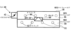
図5の実施形態は、前述の実施形態に類似しており、吸気マニフォールド38には、吸気マニフォールド38を掃気マニフォールド46と噴射のマニフォールド50とに分割可能な仕切りが同様に設けられている。
The embodiment of FIG. 5 is similar to the previous embodiment, and the
本実施形態では、仕切りは、掃気マニフォールド46から噴射マニフォールド50に過給気を供給することを可能にする通路64を有している内部の壁62からなる。この壁62は、吸気マニフォールド38を実質的に同一な2つの部分に分割することで、吸気マニフォールド38の最大長さにわたって水平方向に延びている。
In this embodiment, the partition comprises an
過給気は、絞り手段42が設けられている過給気入口40を通って掃気マニフォールド46内に流入し、掃気オリフィス48に供給され、それから、通路64を通って噴射マニフォールド50内に流れ込んで噴射オリフィス52に供給される。
The supercharging air flows into the scavenging
図6に示されているように、通路64は、噴射マニフォールド50内に存在している過給気が掃気マニフォールド46内に逆流するのを防止する逆止弁のような逆止手段66を備えていることが有利である。したがって、この逆止手段により、燃料が混合されている過給気が掃気マニフォールド内に逆流するおそれが全く無くなることが保証される。
As shown in FIG. 6, the
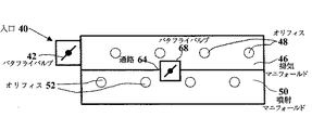
図7に示されているように、通路64は、掃気マニフォールド46から噴射マニフォールド50へ供給される空気の量を制御することを可能にするバタフライバルブなどの絞り手段68を備えていることがさらに有利である。
As shown in FIG. 7, the
図3から図7に示した例では、掃気用マニフォールド46へ過給気を連続して供給した後に、噴射マニフォールド50へ過給気を連続して供給することにより、迂回現象を防止することが可能になる。
In the example shown in FIG. 3 to FIG. 7, a detour phenomenon can be prevented by continuously supplying the supercharged air to the scavenging
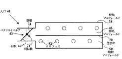
図8の実施形態は、バタフライバルブからなる絞り手段43を備えた過給気入口41を備えている吸気マニフォールド38を示している。この吸気マニフォールド38は、掃気オリフィス48を有している掃気マニフォールド46と噴射オリフィス52を有している噴射マニフォールド50とを画定することを可能にする内部の仕切り70を、自身の容積内に有している。
The embodiment of FIG. 8 shows an
本実施形態では、過給気入口41は、掃気マニフォールド46と噴射マニフォールド50とに同時に供給するように構成されている。このような同時供給を達成するために、仕切り70は、過給気入口41の側端がバタフライバルブ43の水平方向の回転軸72を通る平面と同一平面上に配置されるように、吸気マニフォールド38の最大長さにわたって水平方向に延びている。
In the present embodiment, the supercharged air inlet 41 is configured to supply the scavenging
バタフライバルブ43の両方の羽根74および76は、過給気入口41が閉じた位置で、仕切り70を通る平面に対して直交しないように延びていることが有利である。この図の例では、羽根74は、回転軸72を通っている垂直軸に対して前方、つまり空気の循環方向に傾いており、羽根76は、この循環方向とは逆向きである後方に傾いている。この構成により、バタフライバルブ43が部分的に開いた位置では、バタフライバルブ43の羽根74はこの空気の循環と同じ方向になるので、掃気マニフォールド46に対する過給気の供給が促進される。
Both
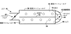
図9は、図8の変形例である他の実施形態を有利に示しており、そのため同じ参照番号を付している。 FIG. 9 advantageously shows another embodiment, which is a variant of FIG. 8, and is therefore given the same reference numerals.
本実施形態では、掃気マニフォールド46は過給気出口78を有しており、噴射マニフォールド50は接続管路82によって空気出口78に接続されている過給気入口80を備えている。この図に点線で示されているように、接続管路82は、掃気マニフォールド46から流入される過給気の量を制御することを可能にする、バタフライバルブなどの絞り手段84を備えていることが好ましい。
In the present embodiment, the scavenging
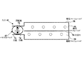
図10は、図8の他の変形例を示す、本発明の他の実施形態である。 FIG. 10 is another embodiment of the present invention showing another modification of FIG.
本変形例では、バタフライバルブ43の回転軸72は、仕切り70を通る平面に対して実質的に垂直に配置されている。
In this modification, the rotating
したがって、過給気は、掃気マニフォールド46と噴射マニフォールド50とに実質的に同一の状態で流入し、バタフライバルブ43の羽根74および76は、掃気マニフォールド46と噴射マニフォールド50との間の過給に関する制御には全く影響を及ぼしていない。
Accordingly, the supercharging air flows into the scavenging
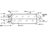
図11は、掃気マニフォールド46と噴射マニフォールド50とを上述のように形成するように、吸気マニフォールド38が仕切り86によって分割されている、他の実施形態である。
FIG. 11 is another embodiment in which the
掃気マニフォールド46は絞り手段90を備えた過給気入口88を備えており、また、噴射マニフォールド50は絞り手段94を備えた過給気入口92を備えている。
The scavenging
掃気用マニフォールド46は、たとえばバタフライバルブの形態の絞り手段102を有利に備えている接続管路100によって噴射マニフォールド50に設けられている空気入口98に連通している過給気出口96を有していることが好ましい。
The scavenging
図8から図11に示した実施形態では、掃気マニフォールド46と噴射マニフォールド50への過給気の供給は実質的に同時に実行され、これらのマニフォールドは同一の空気入口を介して供給され、あるいは各々のマニフォールドが特別の過給気入口を介して供給されている。これにより、迂回現象を防止することも可能になる。
In the embodiment shown in FIGS. 8-11, the supply of supercharging air to the scavenging
本発明は、上述の実施形態に限定されず、あらゆる変形例を含んでいる。 The present invention is not limited to the above-described embodiment, and includes all modifications.
図3から図7に関連して説明した例においては、掃気マニフォールド46と噴射マニフォールド50は過給気がこの順番で供給されることについて特に説明した。
In the example described with reference to FIGS. 3 to 7, the scavenging
この構成は、エンジンが高負荷で動作するときには特に有利である。部分負荷で動作する場合には、空気入口40を噴射マニフォールド50上に配置することによって、空気を噴射マニフォールド50内に供給し、それから掃気マニフォールド46内に供給することにより、空気の供給を逆の順序にすることが可能である。
This configuration is particularly advantageous when the engine operates at high loads. When operating at partial load, air supply is reversed by providing air into the
さらに、図8および図9に示されているケースでは、バタフライバルブ43の羽根74および76の傾きは、掃気マニフォールド46への過給気の供給に好都合である。この傾きは、羽根76が前方に傾き、羽根74が後方に傾くように逆向きにすることが可能である。その場合、過給気の供給は、噴射マニフォールド50の高さで有利になる。
Further, in the case shown in FIGS. 8 and 9, the inclination of the
10 シリンダ
12,14 過給気吸気手段
16,18 吸気管
20,22 吸気弁
24 燃料噴射手段
26 排気手段
28 排気管
30 遮断手段
32 シリンダヘッド
33 エンジンブロック
34 ピストン
36 燃焼室
38 空気供給手段(吸気マニフォールド)
40,41,58,80,88,92,98 入口
42,43,60,68,84,90,94,102 絞り手段(バタフライバルブ)
44,62,70,86 仕切り
46 第1のマニフォールド半体(掃気マニフォールド)
48,52 オリフィス
50 第2のマニフォールド半体(噴射マニフォールド)
54,78,96 出口
56 管路
62 内部の壁
64 通路
66 逆止手段(逆止弁)
72 回転軸
74,76 羽根
82,100 接続管路
10
40, 41, 58, 80, 88, 92, 98
44, 62, 70, 86
48, 52
54, 78, 96
72 Rotating
Claims (15)
前記供給手段(38)は、前記吸気手段(12,14)の各々の種類用の特別な過給気供給装置(46,50)を有していることを特徴とする、特に間接噴射の過給式内燃エンジン。 One type is supercharging air intake means (12) in which fuel is not mixed, and the other type is supercharging air intake means (14) in which fuel is mixed. It has at least one cylinder (10) provided with intake air intake means (12, 14), and is supplied with supercharged air to the intake means by supply means (38), in particular supercharged internal combustion with indirect injection. In the engine,
The supply means (38) has a special supercharger supply device (46, 50) for each type of the intake means (12, 14), in particular excessive indirect injection. Supply type internal combustion engine.
各々の種類の前記吸気手段に過給気を別々に供給することを特徴とする、過給気の供給方法。 One type is supercharging air intake means (12) in which fuel is not mixed, and the other type is supercharging air intake means (14) in which fuel is mixed. It has at least one cylinder (10) provided with intake air intake means (12, 14), and is supplied with supercharged air to the intake means by supply means (38), in particular supercharged internal combustion with indirect injection. In a method for supplying supercharged air for an engine,
A method of supplying supercharged air, wherein supercharged air is separately supplied to each type of intake means.
Applications Claiming Priority (1)
| Application Number | Priority Date | Filing Date | Title |
|---|---|---|---|
| FR0307578A FR2856435B1 (en) | 2003-06-20 | 2003-06-20 | INTERNAL COMBUSTION ENGINE WITH INDIRECT INJECTION TO SWEEP GAS SCAN AND METHOD OF SUPPLYING SURALIMENT AIR FOR SUCH AN ENGINE |
Publications (2)
| Publication Number | Publication Date |
|---|---|
| JP2005009495A true JP2005009495A (en) | 2005-01-13 |
| JP4596417B2 JP4596417B2 (en) | 2010-12-08 |
Family
ID=33396832
Family Applications (1)
| Application Number | Title | Priority Date | Filing Date |
|---|---|---|---|
| JP2004179473A Expired - Fee Related JP4596417B2 (en) | 2003-06-20 | 2004-06-17 | Indirect injection supercharged internal combustion engine for scavenging combustion gas and method for supplying supercharged air to the engine |
Country Status (5)
| Country | Link |
|---|---|
| US (1) | US7082764B2 (en) |
| EP (1) | EP1489283B1 (en) |
| JP (1) | JP4596417B2 (en) |
| DE (1) | DE602004015530D1 (en) |
| FR (1) | FR2856435B1 (en) |
Cited By (1)
| Publication number | Priority date | Publication date | Assignee | Title |
|---|---|---|---|---|
| JP2010285993A (en) * | 2009-06-12 | 2010-12-24 | IFP Energies Nouvelles | Method of controlling intake of supercharged internal combustion engine including burnt gas scavenging operation |
Families Citing this family (9)
| Publication number | Priority date | Publication date | Assignee | Title |
|---|---|---|---|---|
| FR2863006B1 (en) * | 2003-12-02 | 2006-02-24 | Inst Francais Du Petrole | METHOD FOR CONTROLLING AN OVERLAYING MOTOR, IN PARTICULAR AN INDIRECT INJECTION ENGINE, AND ENGINE USING SUCH A METHOD |
| FR2886342B1 (en) * | 2005-05-24 | 2010-08-27 | Inst Francais Du Petrole | METHOD FOR CONTROLLING SCAN OF BURNED GASES OF AN INDIRECT INJECTION ENGINE, ESPECIALLY SUPERCURRENT MOTOR, AND ENGINE USING SUCH A METHOD |
| US7275516B1 (en) * | 2006-03-20 | 2007-10-02 | Ford Global Technologies, Llc | System and method for boosted direct injection engine |
| US7673617B2 (en) * | 2007-06-14 | 2010-03-09 | Institut Francis Du Petrole | Indirect-injection internal-combustion engine, notably spark-ignition supercharged engine, with two intake means for carrying out a burnt gas scavenging stage |
| FR2920034B1 (en) * | 2007-08-14 | 2009-10-02 | Inst Francais Du Petrole | PROCESS FOR REINTRODUCING EXHAUST GASES AT THE INTAKE OF AN INTERNAL COMBUSTION ENGINE AND ENGINE USING SUCH A METHOD |
| FR2955358B1 (en) * | 2010-01-19 | 2012-06-08 | Inst Francais Du Petrole | METHOD FOR SCANNING RESIDUAL BURN GASES OF A MULTI-CYLINDER MOTOR WITH SUPERIOR DIRECT INJECTION INTERNAL COMBUSTION ENGINE OPERATING AT PARTIAL LOADS |
| FR2966199B1 (en) * | 2010-10-19 | 2012-12-07 | Motorisations Aeronautiques | INTAKE DISTRIBUTOR HAVING AN AIR INLET BREAKER DEVICE |
| ES2542304B1 (en) * | 2014-01-02 | 2016-05-12 | Nairex Business, S.L. | INTERNAL COMBUSTION ENGINE WITH PRESSURE DISTRIBUTION CHAMBER WITH MULTIPLE INDEPENDENT ADMISSIONS |
| FR3085439B1 (en) * | 2018-08-30 | 2021-07-16 | Ifp Energies Now | DEVICE AND CONTROL SYSTEM OF AN INTERNAL COMBUSTION ENGINE WITH DOUBLE INTAKE AND SCAN |
Citations (5)
| Publication number | Priority date | Publication date | Assignee | Title |
|---|---|---|---|---|
| JPH03151532A (en) * | 1989-11-07 | 1991-06-27 | Daihatsu Motor Co Ltd | Two-cycle engine |
| JPH03151531A (en) * | 1989-11-07 | 1991-06-27 | Daihatsu Motor Co Ltd | Two-cycle engine |
| JPH06330758A (en) * | 1993-05-24 | 1994-11-29 | Mazda Motor Corp | Intake system of engine |
| JP2003239807A (en) * | 2002-02-19 | 2003-08-27 | Walbro Japan Inc | Butterfly throttle valve type carburetor for stratified scavenging internal combustion engine |
| JP2006514719A (en) * | 2002-07-02 | 2006-05-11 | アクティエボラゲット エレクトロラックス | Additional air control valve for 2-stroke engines |
Family Cites Families (15)
| Publication number | Priority date | Publication date | Assignee | Title |
|---|---|---|---|---|
| US1593989A (en) * | 1923-05-28 | 1926-07-27 | Rafter Albert | Internal-explosion engine |
| GB2115485B (en) * | 1982-02-17 | 1987-01-07 | Nat Res Dev | Stratified charge engines |
| FR2617240B1 (en) * | 1987-06-26 | 1992-10-02 | Inst Francais Du Petrole | DEVICE AND METHOD FOR PRESSURIZING CARBIDE MIXTURE INTO THE CYLINDER OF AN ENGINE |
| US4809649A (en) * | 1987-11-23 | 1989-03-07 | Thomassen International B.V. | Four-stroke internal-combustion engine and procedure for operating such an engine |
| US5230320A (en) * | 1991-06-27 | 1993-07-27 | Mazda Motor Corporation | Intake and exhaust control system for automobile engine |
| GB9222353D0 (en) * | 1992-10-23 | 1992-12-09 | Ricardo Consulting Eng | Spark ignited internal combustion engines |
| JPH07145740A (en) * | 1993-09-30 | 1995-06-06 | Mazda Motor Corp | Power train provided with engine having mechanical supercharger |
| GB2287985A (en) * | 1994-03-19 | 1995-10-04 | Ford Motor Co | Multi-cylinder two-stroke engine charge intake system |
| US6032634A (en) * | 1994-11-02 | 2000-03-07 | Hitachi, Ltd. | Air induction system for internal-combustion engine |
| US5553580A (en) * | 1995-01-13 | 1996-09-10 | Ganoung; David P. | Stratified charge engines and method for their operation |
| JPH09217628A (en) * | 1996-02-13 | 1997-08-19 | Yamaha Motor Co Ltd | Two cycle engine |
| US6951211B2 (en) * | 1996-07-17 | 2005-10-04 | Bryant Clyde C | Cold air super-charged internal combustion engine, working cycle and method |
| US5857450A (en) * | 1997-06-24 | 1999-01-12 | Brunswick Corporation | Low emission two cycle engine using two segment piston |
| JP4006789B2 (en) * | 1997-09-22 | 2007-11-14 | 日産自動車株式会社 | Intake device for internal combustion engine |
| FR2841294B1 (en) * | 2002-06-21 | 2007-04-06 | Inst Francais Du Petrole | METHOD FOR CONTROLLING AN INDIRECT INDIRECT INJECTION ENGINE AND ENGINE USING SUCH A METHOD |
-
2003
- 2003-06-20 FR FR0307578A patent/FR2856435B1/en not_active Expired - Fee Related
-
2004
- 2004-05-19 DE DE602004015530T patent/DE602004015530D1/en not_active Expired - Lifetime
- 2004-05-19 EP EP04291300A patent/EP1489283B1/en not_active Expired - Lifetime
- 2004-06-17 JP JP2004179473A patent/JP4596417B2/en not_active Expired - Fee Related
- 2004-06-21 US US10/870,964 patent/US7082764B2/en not_active Expired - Lifetime
Patent Citations (5)
| Publication number | Priority date | Publication date | Assignee | Title |
|---|---|---|---|---|
| JPH03151532A (en) * | 1989-11-07 | 1991-06-27 | Daihatsu Motor Co Ltd | Two-cycle engine |
| JPH03151531A (en) * | 1989-11-07 | 1991-06-27 | Daihatsu Motor Co Ltd | Two-cycle engine |
| JPH06330758A (en) * | 1993-05-24 | 1994-11-29 | Mazda Motor Corp | Intake system of engine |
| JP2003239807A (en) * | 2002-02-19 | 2003-08-27 | Walbro Japan Inc | Butterfly throttle valve type carburetor for stratified scavenging internal combustion engine |
| JP2006514719A (en) * | 2002-07-02 | 2006-05-11 | アクティエボラゲット エレクトロラックス | Additional air control valve for 2-stroke engines |
Cited By (1)
| Publication number | Priority date | Publication date | Assignee | Title |
|---|---|---|---|---|
| JP2010285993A (en) * | 2009-06-12 | 2010-12-24 | IFP Energies Nouvelles | Method of controlling intake of supercharged internal combustion engine including burnt gas scavenging operation |
Also Published As
| Publication number | Publication date |
|---|---|
| EP1489283B1 (en) | 2008-08-06 |
| DE602004015530D1 (en) | 2008-09-18 |
| EP1489283A1 (en) | 2004-12-22 |
| JP4596417B2 (en) | 2010-12-08 |
| US20040255907A1 (en) | 2004-12-23 |
| US7082764B2 (en) | 2006-08-01 |
| FR2856435A1 (en) | 2004-12-24 |
| FR2856435B1 (en) | 2005-09-23 |
Similar Documents
| Publication | Publication Date | Title |
|---|---|---|
| JPH0663452B2 (en) | 2-cycle internal combustion engine | |
| CN105556100A (en) | Operation of a quantity-controlled internal combustion engine having cylinder deactivation | |
| JP4596417B2 (en) | Indirect injection supercharged internal combustion engine for scavenging combustion gas and method for supplying supercharged air to the engine | |
| JP6591994B2 (en) | Gaseous fuel combustion system for internal combustion engines | |
| JP2001263173A (en) | Four cycle engine | |
| US6513484B1 (en) | Boosted direct injection stratified charge gasoline engines | |
| JP2011508140A (en) | Internal combustion engine and method for modifying an internal combustion engine | |
| JP2019065778A (en) | Control device of internal combustion engine | |
| JP2010031685A (en) | Spark ignition internal combustion engine | |
| JPS606066A (en) | Cooling device for fuel injection valve in dual fuel engine | |
| JPH10252486A (en) | Intake/exhaust device for internal combustion engine | |
| JPH03138419A (en) | Supercharger of engine | |
| JP2010031688A (en) | Spark-ignition internal combustion engine | |
| JP2020186696A (en) | Internal combustion engine with supercharger | |
| JPH0663453B2 (en) | 2-cycle internal combustion engine | |
| JPH0681658A (en) | Two cycle engine having selective control means of sending-in charge to combustion chamber | |
| JP2010031687A (en) | Spark ignition internal combustion engine | |
| JP2889973B2 (en) | Multi-cylinder sub-chamber lean-burn gas engine | |
| JP2865672B2 (en) | Mixture compression type two-stroke internal combustion engine | |
| JPS603942Y2 (en) | Diesel engine air supply system | |
| EP0046156B1 (en) | Turbocharged engine with pressurized gas recirculation | |
| JP2004176620A (en) | Overhead valve type multiple cylinder engine capable of two-cycle operation | |
| JP6548571B2 (en) | Internal combustion engine | |
| SU1633149A1 (en) | Internal combustion engine | |
| JPS59147867A (en) | Fuel injection type internal-combustion engine |
Legal Events
| Date | Code | Title | Description |
|---|---|---|---|
| A621 | Written request for application examination |
Free format text: JAPANESE INTERMEDIATE CODE: A621 Effective date: 20070329 |
|
| A131 | Notification of reasons for refusal |
Free format text: JAPANESE INTERMEDIATE CODE: A131 Effective date: 20091028 |
|
| A601 | Written request for extension of time |
Free format text: JAPANESE INTERMEDIATE CODE: A601 Effective date: 20100128 |
|
| A602 | Written permission of extension of time |
Free format text: JAPANESE INTERMEDIATE CODE: A602 Effective date: 20100202 |
|
| A521 | Request for written amendment filed |
Free format text: JAPANESE INTERMEDIATE CODE: A523 Effective date: 20100226 |
|
| A131 | Notification of reasons for refusal |
Free format text: JAPANESE INTERMEDIATE CODE: A131 Effective date: 20100407 |
|
| A521 | Request for written amendment filed |
Free format text: JAPANESE INTERMEDIATE CODE: A523 Effective date: 20100705 |
|
| TRDD | Decision of grant or rejection written | ||
| A01 | Written decision to grant a patent or to grant a registration (utility model) |
Free format text: JAPANESE INTERMEDIATE CODE: A01 Effective date: 20100825 |
|
| A01 | Written decision to grant a patent or to grant a registration (utility model) |
Free format text: JAPANESE INTERMEDIATE CODE: A01 |
|
| A61 | First payment of annual fees (during grant procedure) |
Free format text: JAPANESE INTERMEDIATE CODE: A61 Effective date: 20100915 |
|
| R150 | Certificate of patent or registration of utility model |
Ref document number: 4596417 Country of ref document: JP Free format text: JAPANESE INTERMEDIATE CODE: R150 Free format text: JAPANESE INTERMEDIATE CODE: R150 |
|
| FPAY | Renewal fee payment (event date is renewal date of database) |
Free format text: PAYMENT UNTIL: 20131001 Year of fee payment: 3 |
|
| R250 | Receipt of annual fees |
Free format text: JAPANESE INTERMEDIATE CODE: R250 |
|
| R250 | Receipt of annual fees |
Free format text: JAPANESE INTERMEDIATE CODE: R250 |
|
| R250 | Receipt of annual fees |
Free format text: JAPANESE INTERMEDIATE CODE: R250 |
|
| R250 | Receipt of annual fees |
Free format text: JAPANESE INTERMEDIATE CODE: R250 |
|
| R250 | Receipt of annual fees |
Free format text: JAPANESE INTERMEDIATE CODE: R250 |
|
| R250 | Receipt of annual fees |
Free format text: JAPANESE INTERMEDIATE CODE: R250 |
|
| LAPS | Cancellation because of no payment of annual fees |

