JP6162674B2 - compact - Google Patents

compact Download PDF

Info

Publication number
JP6162674B2
JP6162674B2 JP2014211759A JP2014211759A JP6162674B2 JP 6162674 B2 JP6162674 B2 JP 6162674B2 JP 2014211759 A JP2014211759 A JP 2014211759A JP 2014211759 A JP2014211759 A JP 2014211759A JP 6162674 B2 JP6162674 B2 JP 6162674B2
Authority
JP
Japan
Prior art keywords
movable wall
wall portion
puff
end side
compact
Prior art date
Legal status (The legal status is an assumption and is not a legal conclusion. Google has not performed a legal analysis and makes no representation as to the accuracy of the status listed.)
Active
Application number
JP2014211759A
Other languages
Japanese (ja)
Other versions
JP2016077513A (en
Inventor
山中 康弘
康弘 山中
彰則 佐藤
彰則 佐藤
有里 風巻
有里 風巻
Current Assignee (The listed assignees may be inaccurate. Google has not performed a legal analysis and makes no representation or warranty as to the accuracy of the list.)
MFV Co Ltd
Original Assignee
MFV Co Ltd
Priority date (The priority date is an assumption and is not a legal conclusion. Google has not performed a legal analysis and makes no representation as to the accuracy of the date listed.)
Filing date
Publication date
Application filed by MFV Co Ltd filed Critical MFV Co Ltd
Priority to JP2014211759A priority Critical patent/JP6162674B2/en
Publication of JP2016077513A publication Critical patent/JP2016077513A/en
Application granted granted Critical
Publication of JP6162674B2 publication Critical patent/JP6162674B2/en
Active legal-status Critical Current
Anticipated expiration legal-status Critical

Links

Images

Landscapes

  • Closures For Containers (AREA)

Description

本発明は、パフ等の化粧用具を収納する化粧用具収納凹部を備えるコンパクトに関するものである。   The present invention relates to a compact provided with a cosmetic tool storage recess for storing a cosmetic tool such as a puff.

コンパクトには容器本体と容器本体の上端開口を開閉自在に塞ぐ蓋体とを備え、容器本体に上端が開口した化粧用具収納凹部が設けられたものがある。
この種の従来のコンパクトには、容器本体の後壁部にパフ(化粧用具)を受ける支持突片がヒンジピン廻りに回動自在にヒンジ係合され、蓋体を開方向に大きく回動させた際に、支持突片の後壁部が蓋体後端により圧接されて支持突片が開方向に回動するように構成されたものがある。この場合、蓋体を大きく開くと同時に支持突片が化粧用具収納凹部の底壁から上方に揺動して、パフが支持突片と共に上方に揺動して持ち上がるため、持ち上がった一端部を摘んでパフを容易に取り出して使用することができるようになっている(例えば特許文献1)。
Some of the compacts include a container body and a lid that covers the upper end opening of the container body so as to be openable and closable.
In this type of conventional compact, a support protrusion for receiving a puff (cosmetic tool) on the rear wall portion of the container body is hinge-engaged so as to be rotatable around a hinge pin, and the lid is greatly rotated in the opening direction. In some cases, the rear wall portion of the support protrusion is pressed against the rear end of the lid, and the support protrusion rotates in the opening direction. In this case, the support protrusion is swung upward from the bottom wall of the cosmetic device receiving recess at the same time as the lid is opened, and the puff is swung upward together with the support protrusion. Therefore, the puff can be easily taken out and used (for example, Patent Document 1).

また、他の従来のコンパクトには、パフと化粧用具収納凹部の底壁との間の一部に隙間を設け、隙間に対応するパフの一部を押圧することにより、該一部を下降させてパフの他端部を持ち上げさせ、これにより、持ち上がったパフの他端部を摘んでパフを容易に取り出して使用できるようにしたものがある(例えば特許文献2)。   In another conventional compact, a gap is provided in a part between the puff and the bottom wall of the cosmetic device housing recess, and the part of the puff corresponding to the gap is pressed down to lower the part. The other end of the puff is lifted, and the other end of the raised puff is picked up so that the puff can be easily taken out and used (for example, Patent Document 2).

実開昭61−197906号公報Japanese Utility Model Publication No. 61-197906 登録実用新案3053663号公報Registered Utility Model No. 3056363

しかし、従来では、前者の場合、化粧用具収納凹部とは別個に支持突片を設け、これを回動自在に支持する必要があり、部品数が増えて製造コストも増大するし、コンパクト全体も分厚くなるという問題があった。
また、後者の場合、部品数は増えないが、底壁に隙間が必要になるため、コンパクト自体が分厚くなるし、パフに加工を施すことが必要な場合もあり、この点から製造費用が高くなるという問題があった。
However, conventionally, in the former case, it is necessary to provide a support protrusion separately from the cosmetic tool housing recess, and to support this in a freely rotatable manner, increasing the number of parts, increasing the manufacturing cost, and reducing the overall compact size. There was a problem of becoming thicker.
In the latter case, the number of parts does not increase, but since a gap is required in the bottom wall, the compact itself becomes thicker, and it may be necessary to process the puff. There was a problem of becoming.

本発明は上記問題点に鑑み、部品数を増やさず、コンパクト自体も分厚くならずに済んで安価に製造することができ、しかもパフ等の化粧用具を取り出し易くなし得るコンパクトを提供することを目的としている。   SUMMARY OF THE INVENTION In view of the above problems, the present invention has an object to provide a compact that does not increase the number of parts, can be manufactured at low cost without increasing the thickness of the compact itself, and can easily take out cosmetic tools such as puffs. It is said.

本発明における課題解決のための具体的手段は、次の通りである。
この技術的課題を解決する本発明の技術的手段は、上端が開口した化粧用具収納凹部7を備えるコンパクトであって、
化粧用具収納凹部7に収納した化粧用具9の一端側を下方押圧によって下方移動させて他端側を持ち上げるように、化粧用具収納凹部7の底壁17の一端側に下方に弾性変形可能な可動壁部29が設けられている点にある。
Specific means for solving the problems in the present invention are as follows.
The technical means of the present invention for solving this technical problem is a compact comprising a cosmetic tool storage recess 7 whose upper end is open,
A moveable elastically deformable downward to one end side of the bottom wall 17 of the cosmetic tool storage recess 7 so that one end side of the cosmetic tool 9 stored in the cosmetic tool storage recess 7 is moved downward by pressing downward and the other end side is lifted. The wall portion 29 is provided.

また、本発明の他の技術的手段は、前記底壁17に、一端部を残して可動壁部29の外周を囲繞するように可動壁形成溝30が設けられて、前記可動壁部29が底壁17の可動壁形成溝30の内側に形成されている点にある。
また、本発明の他の技術的手段は、可動壁部29はその一端部を支点に弾性変形により下方へ傾斜揺動自在とされ、可動壁部29の他端側に、化粧用具9が可動壁部29上を滑降するのを規制する滑降規制片35が突設されている点にある。
According to another technical means of the present invention, a movable wall forming groove 30 is provided on the bottom wall 17 so as to surround the outer periphery of the movable wall portion 29 except for one end thereof. This is in the point formed inside the movable wall forming groove 30 of the bottom wall 17.
Further, according to another technical means of the present invention, the movable wall portion 29 can be tilted and swung downward by elastic deformation with one end portion as a fulcrum, and the cosmetic tool 9 is movable on the other end side of the movable wall portion 29. The downhill restricting piece 35 for restricting the downhill on the wall portion 29 is provided in a protruding manner.

また、本発明の他の技術的手段は、可動壁部29の他端側に、可動壁部29の下方揺動を規制するように化粧用具収納凹部7の可動壁部29以外の固定側に係合するストッパー47が設けられている点にある。
また、本発明の他の技術的手段は、前記可動壁部29は、底壁17の一部を他の部分よりも弾性変形し易い弾性材で構成してなる点にある。
In addition, another technical means of the present invention is provided on the other end side of the movable wall portion 29 on the fixed side other than the movable wall portion 29 of the cosmetic device housing recess 7 so as to restrict the downward swing of the movable wall portion 29. An engaging stopper 47 is provided.
In addition, another technical means of the present invention is that the movable wall portion 29 is formed of an elastic material in which a part of the bottom wall 17 is more easily elastically deformed than other parts.

本発明によれば、化粧用具収納凹部に収納されたパフの一端側を下方押圧によって下方移動させて他端側を簡単に持ち上げることができ、これにより、持ち上がった化粧用具の他端部を摘んで化粧用具を容易に取り出して使用できる。
しかも、化粧用具収納凹部の底壁に可動壁形成溝を設けたり、底壁の一部を弾性変形し易い材料で構成したりすることによって、部品数を増やすことなく底壁に可動壁部を設けることができ、コンパクト自体が分厚くなるようなこともなくなり、安価に製造することができる。
According to the present invention, the one end side of the puff stored in the cosmetic tool storage recess can be moved downward by pressing downward, and the other end side can be easily lifted, whereby the other end portion of the lifted cosmetic tool can be gripped. Therefore, the cosmetic tool can be easily taken out and used.
In addition, by providing a movable wall forming groove on the bottom wall of the cosmetic device storage recess, or by configuring a part of the bottom wall with a material that is easily elastically deformed, the movable wall portion can be formed on the bottom wall without increasing the number of parts. Therefore, the compact itself does not become thick, and can be manufactured at low cost.

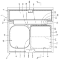
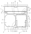
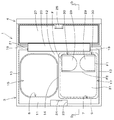
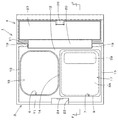
本発明の第1実施形態を示すコンパクトの平面図である。It is a compact top view which shows 1st Embodiment of this invention. 同図1のA−A線断面図である。It is the sectional view on the AA line of the same FIG. 第2実施形態を示すコンパクトの平面図である。It is a compact top view which shows 2nd Embodiment. 同図3のB−B線断面図である。It is a BB sectional view taken on the line of FIG. 第3実施形態を示すコンパクトの平面図である。It is a compact top view which shows 3rd Embodiment. 同図5のC−C線断面図である。It is CC sectional view taken on the line of FIG. 第4実施形態を示すコンパクトの側面断面図である。It is side surface sectional drawing of the compact which shows 4th Embodiment. 第5実施形態を示すコンパクトの平面図である。It is a compact top view which shows 5th Embodiment. 同図3のD−D線断面図である。It is the DD sectional view taken on the line of FIG. 第6実施形態を示すコンパクトの平面図である。It is a compact top view which shows 6th Embodiment. 同図10のE−E線断面図である。It is the EE sectional view taken on the line of FIG. 第7実施形態を示すコンパクトの平面図である。It is a compact top view which shows 7th Embodiment. 同図12のF−F線断面図で、(a)はパフを化粧用具収納凹部に収納した状態であり、(b)はパフの他端部を化粧用具収納凹部から持ち上げた状態である。12 is a cross-sectional view taken along line FF in FIG. 12, where (a) shows a state where the puff is housed in the cosmetic tool housing recess, and (b) shows a state where the other end of the puff is lifted from the cosmetic tool housing recess.

以下、本発明の実施の形態を図面に基づいて説明する。
図1及び図2は本発明の第1実施形態を示している。図1及び図2において、コンパクト1は、容器本体3と容器本体3の上端開口を開閉自在に塞ぐ蓋体4とを備えている。
容器本体3は、弾性を有する硬質合成樹脂等により左右に長い長方形状に形成されている。容器本体3の左右方向の一方側に、上端が開口した長方形の化粧料収納凹部6が形成され、他方側に、上端が開口した長方形の化粧用具収納凹部(パフ収納凹部)7が形成されている。化粧料収納凹部6に白粉等の化粧料が収納され、化粧用具収納凹部7に化粧用具であるパフ9が収納されている。
Hereinafter, embodiments of the present invention will be described with reference to the drawings.
1 and 2 show a first embodiment of the present invention. 1 and 2, the compact 1 includes a container body 3 and a lid body 4 that closes an upper end opening of the container body 3 so as to be openable and closable.
The container main body 3 is formed in a rectangular shape that is long to the left and right by elastic hard synthetic resin or the like. A rectangular cosmetic storage recess 6 having an open upper end is formed on one side of the container body 3 in the left-right direction, and a rectangular cosmetic tool storage recess (puff storage recess) 7 having an open upper end is formed on the other side. Yes. Cosmetics such as white powder are stored in the cosmetic storage recess 6, and a puff 9 that is a cosmetic tool is stored in the cosmetic storage recess 7.

而して、容器本体3は、化粧料収納凹部6及び化粧用具収納凹部7の周囲に前壁11と後壁12と左右一対の側壁13とを有し、化粧料収納凹部6と化粧用具収納凹部7との間に仕切り壁14を有している。化粧料収納凹部6は長方形の薄板状の底壁15を有し、化粧用具収納凹部7は長方形の薄板状の底壁17を有し、容器本体3の後壁12には左右一対の支持部19が突設されている。   Thus, the container body 3 has a front wall 11, a rear wall 12, and a pair of left and right side walls 13 around the cosmetic storage recess 6 and the cosmetic tool storage recess 7, and the cosmetic storage recess 6 and the cosmetic tool storage. A partition wall 14 is provided between the recess 7. The cosmetic storage recess 6 has a rectangular thin plate-like bottom wall 15, the cosmetic tool storage recess 7 has a rectangular thin plate-like bottom wall 17, and a pair of left and right support portions on the rear wall 12 of the container body 3. 19 is projected.

蓋体4は、硬質合成樹脂等により容器本体3に対応する長方形状に形成されている。蓋体4の後端部に取付部20が突設されている。取付部20を左右の支持部19間に嵌合して枢支軸21を容器本体3の支持部19及び蓋体4の取付部20に打ち込むことにより、蓋体4が、取付部20を介して容器本体3の後壁12に枢支軸21廻りに開閉自在になるようにヒンジ結合されている。   The lid 4 is formed in a rectangular shape corresponding to the container main body 3 with a hard synthetic resin or the like. A mounting portion 20 protrudes from the rear end portion of the lid body 4. By fitting the attachment portion 20 between the left and right support portions 19 and driving the pivot shaft 21 into the support portion 19 of the container body 3 and the attachment portion 20 of the lid body 4, the lid body 4 is interposed via the attachment portion 20. The container body 3 is hinged to the rear wall 12 so that it can be opened and closed around the pivot shaft 21.

容器本体3の前壁11に、係止凹部23が設けられ、係止凹部23の内壁上部に前方突出した係止部24が設けられている。蓋体4の前端部には、下方に向けて鉤形に突出した係合部25が設けられ、該係合部25は弾性変形によって係止部24に下側から係脱自在に係合し、これにより蓋体4を閉塞状態に保持するようになっている。
蓋体4の内面側に、鏡体27が設けられている。鏡体27はその鏡面を容器本体3側に向けた状態で蓋体4に埋設固定されている。
A locking recess 23 is provided on the front wall 11 of the container body 3, and a locking portion 24 protruding forward is provided on the inner wall upper portion of the locking recess 23. The front end of the lid 4 is provided with an engaging portion 25 projecting downward in a bowl shape. The engaging portion 25 is engaged with the engaging portion 24 from the lower side by elastic deformation so as to be freely disengaged. Thus, the lid 4 is held in a closed state.
A mirror body 27 is provided on the inner surface side of the lid body 4. The mirror body 27 is embedded and fixed in the lid body 4 with its mirror surface facing the container body 3 side.

化粧用具収納凹部7の底壁17の後端側(一端側)に下方に弾性変形可能な可動壁部29が設けられている。底壁17の後端側に平面視で前方が開口したコの字状の可動壁形成溝30が形成され、可動壁形成溝30は左右方向の後溝部32と前後方向の左右一対の側溝部33とを有している。而して、一端部を残して可動壁部29の外周を囲繞するように可動壁形成溝30が底壁17に設けられて、可動壁部29が底壁17の可動壁形成溝30の内側に形成され、可動壁部29の前方に固定壁部31が形成されている。   A movable wall 29 that is elastically deformable downward is provided on the rear end side (one end side) of the bottom wall 17 of the cosmetic device housing recess 7. A U-shaped movable wall forming groove 30 having a front opening in a plan view is formed on the rear end side of the bottom wall 17, and the movable wall forming groove 30 includes a rear groove portion 32 in the left-right direction and a pair of left and right side groove portions in the front-rear direction. 33. Thus, the movable wall forming groove 30 is provided in the bottom wall 17 so as to surround the outer periphery of the movable wall portion 29 except for one end, and the movable wall portion 29 is located inside the movable wall forming groove 30 of the bottom wall 17. A fixed wall portion 31 is formed in front of the movable wall portion 29.

従って、可動壁部29はその前端部(1点鎖線F1)を支点に弾性変形により下方へ傾斜揺動自在とされており、化粧用具収納凹部7に収納したパフ9の後端側(一端側)を下方に押圧することによって、可動壁部29が前端部を支点に後下がりに傾斜揺動して、化粧用具収納凹部7の下面よりも下方に突出し、これによりパフ9が可動壁部29の前端部(1点鎖線F1)を支点に揺動し、パフ9の後端側(一端側)を下方移動させてパフ9の前端側(他端側)を持ち上げるようになっている。   Therefore, the movable wall portion 29 can be tilted and swung downward by elastic deformation with the front end portion (one-dot chain line F1) as a fulcrum, and the rear end side (one end side) of the puff 9 stored in the cosmetic device storing recess 7 ) Downwardly, the movable wall portion 29 tilts and swings backward and downward with the front end portion as a fulcrum, and protrudes downward from the lower surface of the cosmetic device receiving recess 7, whereby the puff 9 is moved to the movable wall portion 29. The front end portion (one-dot chain line F1) of the puff 9 is swung around a fulcrum, and the rear end side (one end side) of the puff 9 is moved downward to lift the front end side (the other end side) of the puff 9.

可動壁部29の後端側(他端側)に、パフ9が可動壁部29上を後方に滑降するのを規制する滑降規制片35が上方突設されている。
前記第1実施形態によれば、パフ9を使用して化粧をする場合、コンパクト1の蓋体4を開いた後、図2に示すように、化粧用具収納凹部7に収納したパフ9の後端側を指で下方に押圧すると、可動壁部29がその前端部(1点鎖線F1)を支点に弾性変形により下方へ傾斜揺動して、可動壁部29が化粧用具収納凹部7の下面よりも下方に突出し、これによりパフ29が可動壁部29の前端部(1点鎖線F1)を支点に揺動し、パフ9の後端側を下方移動させてパフ9の前端側が持ち上がる。
On the rear end side (the other end side) of the movable wall portion 29, a downhill regulating piece 35 that restricts the puff 9 from sliding down on the movable wall portion 29 protrudes upward.
According to the first embodiment, when makeup is performed using the puff 9, after the lid 4 of the compact 1 is opened, as shown in FIG. When the end side is pressed downward with a finger, the movable wall 29 tilts and swings downward by elastic deformation with its front end (one-dot chain line F1) as a fulcrum, so that the movable wall 29 is the lower surface of the cosmetic device housing recess 7 Thus, the puff 29 swings about the front end portion (one-dot chain line F1) of the movable wall portion 29 as a fulcrum, and the rear end side of the puff 9 is moved downward to raise the front end side of the puff 9.

従って、その持ち上がったパフ9の前部を指で摘んでパフ9を容易に取り出して使用できる。また、押圧を解除することによって、可動壁部29は弾性変形の復元力によって元の水平な状態に自動的に戻るため、パフ9を使用した後は、パフ9を従来通り化粧用具収納凹部7に簡単に収納することができる。
また、可動壁部29が下方へ傾斜揺動した際に、パフ9が可動壁部29上を後方に滑降するのを滑降規制片35によって規制することができるため、パフ9が滑降して可動壁部29から後方に突出するのを防止でき、下方へ傾斜揺動した可動壁部29が元の水平な状態に戻るときに、パフ9が可動壁部29と後壁12との間に挟まるのを未然に防止し得る。
Therefore, the front part of the raised puff 9 can be picked up with a finger and the puff 9 can be easily taken out and used. Moreover, since the movable wall 29 automatically returns to the original horizontal state by the restoring force of the elastic deformation by releasing the pressing, after the puff 9 is used, the puff 9 is kept as usual in the cosmetic device receiving recess 7. Can be stored easily.
Further, when the movable wall portion 29 tilts and swings downward, it is possible to restrict the puff 9 from sliding down on the movable wall portion 29 by the downhill regulating piece 35, so that the puff 9 slides down and is movable. The puff 9 is sandwiched between the movable wall portion 29 and the rear wall 12 when the movable wall portion 29 tilted and swung downward can be prevented from protruding backward from the wall portion 29 and returns to the original horizontal state. Can be prevented in advance.

また、鏡体27を見たい場合には、蓋体4を図2に示すように開けばよく、簡単に鏡体27を見ることができ、この際に、可動壁部29が下方へ傾斜揺動することはなくなり、従来(特許文献1)のように鏡を見るときに不必要にパフの前端側が持ち上がるようなこともなくなる。
しかも、化粧用具収納凹部7の底壁17に可動壁形成溝30を設けることによって、部品数を増やすことなく底壁17に可動壁部29を簡単に形成することができ、コンパクト1自体が分厚くなるようなこともなくなり、コンパクト1を安価かつ簡単に製造することができる。
Further, in order to view the mirror body 27, the lid body 4 can be opened as shown in FIG. 2, and the mirror body 27 can be easily viewed. At this time, the movable wall portion 29 tilts downward. It does not move, and the front end side of the puff is not lifted unnecessarily when the mirror is viewed as in the prior art (Patent Document 1).
In addition, by providing the movable wall forming groove 30 in the bottom wall 17 of the cosmetic device receiving recess 7, the movable wall portion 29 can be easily formed in the bottom wall 17 without increasing the number of parts, and the compact 1 itself is thick. The compact 1 can be manufactured inexpensively and easily.

図3及び図4は第2実施形態を示し、底壁17の前端側に、可動壁形成溝30に対向して平面視で後方が開口したコの字状の第2可動壁形成溝38が形成され、第2可動壁形成溝38は左右方向の前溝部39と前後方向の左右一対の側溝部40とを有している。第2可動壁形成溝38はその左右幅が可動壁形成溝30の左右幅よりも小さく、左右側溝部40の後部は可動壁形成溝30における左右側溝部33の前部の左右方向内側に配置されている。   3 and 4 show a second embodiment. A U-shaped second movable wall forming groove 38 having a rear opening in plan view facing the movable wall forming groove 30 is formed on the front end side of the bottom wall 17. The second movable wall forming groove 38 is formed with a front groove portion 39 in the left-right direction and a pair of left and right side groove portions 40 in the front-rear direction. The left and right widths of the second movable wall forming groove 38 are smaller than the left and right widths of the movable wall forming groove 30, and the rear part of the left and right side groove part 40 is disposed on the inner side in the left and right direction of the front part of the left and right side groove part 33 in the movable wall forming groove 30. Has been.

而して、底壁17の第2可動壁形成溝38の内側に第2可動壁部34が形成され、第2可動壁部34は可動壁部29の前端部(1点鎖線F1)を支点に可動壁部29に連動して弾性変形によって前上がりに傾斜揺動するようになっている。その他の点は第1実施形態の場合と同様の構成である。
第2実施形態の場合、化粧用具収納凹部7に収納したパフ9の後部を指で下方に押圧すると、可動壁部29がその前端部(1点鎖線F1)を支点に弾性変形により下方へ傾斜揺動すると共に、第2可動壁部34はその後端部(1点鎖線F1)を支点に可動壁部29に
連動して弾性変形によって前上がりに傾斜揺動し、これによりパフ9が可動壁部29の前端部(1点鎖線F1)を支点に揺動し、パフ9の後端側(一端側)を下方移動させてパフ9の前端側(他端側)が持ち上がり、その持ち上がったパフ9の前端部を指で摘んでパフ9を容易に取り出して使用できる。
Thus, the second movable wall portion 34 is formed inside the second movable wall forming groove 38 of the bottom wall 17, and the second movable wall portion 34 supports the front end portion (one-dot chain line F 1) of the movable wall portion 29. In conjunction with the movable wall portion 29, it is tilted and swung forward and upward by elastic deformation. The other points are the same as those in the first embodiment.
In the case of the second embodiment, when the rear portion of the puff 9 housed in the cosmetic device housing recess 7 is pressed downward with a finger, the movable wall portion 29 is inclined downward by elastic deformation with the front end portion (dashed line F1) as a fulcrum. While swinging, the second movable wall portion 34 tilts and swings upward by elastic deformation in conjunction with the movable wall portion 29 with the rear end portion (one-dot chain line F1) as a fulcrum, whereby the puff 9 is moved to the movable wall. The front end portion (one-dot chain line F1) of the portion 29 is swung around the fulcrum, the rear end side (one end side) of the puff 9 is moved downward, the front end side (the other end side) of the puff 9 is lifted, and the raised puff The front end of 9 can be picked with a finger and the puff 9 can be easily taken out and used.

図5及び図6は第3実施形態を示し、可動壁形成溝30の左右側溝部33が前方に向けて長く形成され、底壁17の可動壁形成溝30の内側に、平面視で前方が開口したコの字状の第2可動壁形成溝38が形成され、この第2可動壁形成溝38は左右方向の後溝部43と前後方向の左右一対の側溝部44とを有している。第2可動壁形成溝38の形成により、可動壁部29には長方板形状の可動壁部本体から前方突出した左右一対の支持脚46が具備され、可動壁部29の前方に固定壁部31が形成され、可動壁部29は左右支持脚46の前端部(1点鎖線F1)を支点に弾性変形により後下がりに下方揺動し、これによりパフ9が固定壁部31の前端部(実線F2)を支点に揺動し、パフ9の後端側(一端側)を下方移動させてパフ9の前端側(他端側)がより大きく持ち上がるように構成されている。その点は前記第1実施形態の場合と同様の構成である。   5 and 6 show a third embodiment, in which the left and right groove portions 33 of the movable wall forming groove 30 are formed long toward the front side, and the front side in the plan view is inside the movable wall forming groove 30 of the bottom wall 17. An opened U-shaped second movable wall forming groove 38 is formed. The second movable wall forming groove 38 includes a rear groove portion 43 in the left-right direction and a pair of left and right side groove portions 44 in the front-rear direction. Due to the formation of the second movable wall forming groove 38, the movable wall portion 29 is provided with a pair of left and right support legs 46 protruding forward from the rectangular plate-shaped movable wall main body, and the fixed wall portion is disposed in front of the movable wall portion 29. 31 is formed, and the movable wall portion 29 swings downward downward by elastic deformation with the front end portion (one-dot chain line F1) of the left and right support legs 46 as a fulcrum, whereby the puff 9 is moved to the front end portion of the fixed wall portion 31 ( The front end side (the other end side) of the puff 9 is lifted more greatly by swinging around the solid line F2) and moving the rear end side (one end side) of the puff 9 downward. This is the same configuration as in the first embodiment.

図7は第4実施形態を示し、可動壁部29の他端側である滑降規制片35の上部にストッパー47が後方突設され、化粧用具収納凹部7の可動壁部29以外の固定側である後壁12の下部に受け片48が前方突設されており、可動壁部29が前端部(1点鎖線F1)を支点に後下がり傾斜揺動したときにストッパー47が受け片48に上側から当接し、これにより可動壁部29の下方揺動を規制するようになっている。その他の点は第3実施形態の場合と同様の構成である。   FIG. 7 shows a fourth embodiment, in which a stopper 47 protrudes rearwardly on the upper part of the downhill restricting piece 35 which is the other end side of the movable wall portion 29, and on the fixed side other than the movable wall portion 29 of the cosmetic device housing recess 7. A receiving piece 48 is projected forward from a lower portion of a certain rear wall 12, and the stopper 47 is located above the receiving piece 48 when the movable wall portion 29 tilts backward and swings with the front end portion (one-dot chain line F <b> 1) as a fulcrum. Thus, the swinging of the movable wall portion 29 is restricted. The other points are the same as those in the third embodiment.

図8及び図9は第5実施形態を示し、底壁17の後端側に、平面視で左右方向外方が開口したコの字状又はC字状の可動壁形成溝30が背中合わせに左右一対設けられている。この左右の可動壁形成溝30は底壁17の左右方向中央部で連続一体に形成されている。底壁17の各可動壁形成溝30の内側に、左右一対の可動壁部29がそれぞれ形成され、これら可動壁部29の前方に固定壁部31が形成されており、各可動壁部29は左右方向外端部(1点鎖線F1)を支点に、左右方向の内方下がりに弾性変形によって下方傾斜するようになっている。   8 and 9 show a fifth embodiment, and a U-shaped or C-shaped movable wall forming groove 30 having an opening in the left and right direction in plan view is provided on the rear end side of the bottom wall 17 in the back-to-back direction. A pair is provided. The left and right movable wall forming grooves 30 are integrally formed at the center in the left-right direction of the bottom wall 17. A pair of left and right movable wall portions 29 are formed inside each movable wall forming groove 30 of the bottom wall 17, and a fixed wall portion 31 is formed in front of these movable wall portions 29. With the outer end in the left-right direction (one-dot chain line F1) as a fulcrum, it is inclined downward by elastic deformation inwardly in the left-right direction.

この場合、化粧用具収納凹部7に収納したパフ9の後端側を指で下方に押圧すると、左右の可動壁部29が左右方向外端部(1点鎖線F1)を支点に弾性変形により下方へ傾斜揺動し、これによりパフ9が固定壁部31の後端部(実線F2)を支点に揺動し、パフ9の後端側を下方移動させてパフ9の前端側(他端側)が大きく持ち上がり、その持ち上がったパフ9の前端部を指で摘んでパフ9を容易に取り出して使用できる。   In this case, when the rear end side of the puff 9 stored in the cosmetic device storing recess 7 is pressed downward with a finger, the left and right movable wall portions 29 are lowered by elastic deformation with the left and right outer end portions (one-dot chain line F1) as a fulcrum. As a result, the puff 9 swings with the rear end portion (solid line F2) of the fixed wall portion 31 as a fulcrum, and the rear end side of the puff 9 is moved downward to the front end side (the other end side) of the puff 9. ) Is lifted greatly, and the front end portion of the lifted puff 9 can be picked up with a finger and the puff 9 can be easily taken out and used.

なお、この第5実施形態の場合、パフ9が可動壁部29を滑降するのを規制する滑降規制片35が省略されているが、これを左右可動壁部29の左右方向内端部にそれぞれ突設するようにしてもよい。
図10及び図11は第6実施形態を示し、可動壁部29の後端部から左右両端部に亘って左右突出片51と後突出片52とを平面視コの字状に一体に上方突設したものであり、後突出片52がパフ9の滑降を規制する滑降規制片35とされている。その他の点は第1実施形態の場合と同様の構成である。
In the case of this fifth embodiment, the downhill restricting piece 35 that restricts the puff 9 from sliding down the movable wall portion 29 is omitted, but this is applied to the left and right inner ends of the left and right movable wall portions 29, respectively. You may make it project.
10 and 11 show a sixth embodiment, in which the left and right projecting pieces 51 and the rear projecting piece 52 are integrally projected upward in a U-shape in plan view from the rear end portion of the movable wall portion 29 to the left and right end portions. The rear projecting piece 52 is a downhill regulating piece 35 that regulates the downfall of the puff 9. The other points are the same as those in the first embodiment.

この第6実施形態の場合、可動壁部29が傾斜揺動した際に滑降規制片35(後突出片52)によってパフ9が滑降するのを防ぐと共に、パフ9が左右に不測に移動するのを左右突出片51によって防ぐことができ、パフ9が可動壁部29から不測に後方及び左右に突出して、パフ9が可動壁部29と後壁12との間に挟まるのをより確実に防止し得る。また、可動壁部29が傾斜揺動した際に、容器本体3の後方や側方から化粧用具収納凹部7内が見えなくなるように左右突出片51と後突出片52とで隠すことができ、体裁がよくなる。   In the case of the sixth embodiment, when the movable wall portion 29 is tilted and swung, the puff 9 is prevented from sliding down by the slide-down regulating piece 35 (rear projecting piece 52), and the puff 9 is moved unexpectedly to the left and right. Can be prevented by the left and right projecting pieces 51, and the puff 9 can be more reliably prevented from unexpectedly projecting rearward and left and right from the movable wall portion 29 and being pinched between the movable wall portion 29 and the rear wall 12. Can do. Further, when the movable wall 29 is tilted and swung, it can be hidden by the left and right protruding pieces 51 and the rear protruding pieces 52 so that the inside of the cosmetic tool storage recess 7 cannot be seen from the rear or side of the container body 3. Appearance is improved.

図12及び図13は第7実施形態を示し、前壁11及び後壁12等と一体に硬質合成樹脂等により構成された底壁本体54の前部に開口部55が設けられ、底壁本体54上に柔軟で弾性に富むエラストマー等の弾性材で構成したカバー壁56が敷設され、カバー壁56には開口部55に嵌合する可動壁部29が一体に下方突設されており、可動壁部29で
開口部55を塞いでいる。従って、底壁17は底壁本体54とカバー壁56と可動壁部29とを備えてなり、可動壁部29は、底壁17の一部を他の部分よりも弾性変形し易い弾性材で構成してなる。
12 and 13 show a seventh embodiment, in which an opening 55 is provided in the front portion of a bottom wall body 54 that is integrally formed of a hard synthetic resin or the like with the front wall 11 and the rear wall 12, and the bottom wall body. A cover wall 56 made of an elastic material such as a flexible and elastic elastomer is laid on 54, and a movable wall portion 29 that fits into the opening 55 is integrally projected downward from the cover wall 56. The opening portion 55 is blocked by the wall portion 29. Therefore, the bottom wall 17 includes a bottom wall main body 54, a cover wall 56, and a movable wall portion 29. The movable wall portion 29 is made of an elastic material that easily elastically deforms a part of the bottom wall 17 as compared with other portions. Consists of.

この第7実施形態の場合、図13(a)に示すように蓋体4を開いた状態から図13(b)に示すように化粧用具収納凹部7に収納したパフ9の後端側を指で下方に押圧すると、可動壁部29が下方に弾性変形し、パフ9の後端側を下方移動させてパフ9の前端側が持ち上がり、その持ち上がったパフ9の前端部を指で摘んでパフ9を容易に取り出して使用できる。   In the case of this seventh embodiment, the rear end side of the puff 9 housed in the cosmetic device housing recess 7 as shown in FIG. 13B from the state in which the lid 4 is opened as shown in FIG. When the pressure is pressed downward, the movable wall portion 29 is elastically deformed downward, the rear end side of the puff 9 is moved downward, the front end side of the puff 9 is lifted, the front end portion of the raised puff 9 is picked with a finger, and the puff 9 Can be easily taken out and used.

なお、前記実施形態では、可動壁部29は底壁17の可動壁形成溝30の内側に形成してなり、又は底壁17の一部を他の部分よりも弾性変形し易い弾性材で構成してなるが、可動壁部29はこのようなものに限定されず、可動壁部29は化粧用具収納凹部7の底壁17の一端側に下方に弾性変形可能に構成されていればよい。
また、前記実施形態では、化粧用具収納凹部7の底壁17の後端側に可動壁部29を設けているが、これに代え、底壁17の前端側に可動壁部29を設けるようにしてもよい。この場合、例えば、底壁17の前端側に平面視で後方が開口したコの字状の可動壁形成溝30を形成し、可動壁部29がその後端部を支点に弾性変形によって前下がりに傾斜揺動するようにしてもよい。
In the embodiment, the movable wall portion 29 is formed inside the movable wall forming groove 30 of the bottom wall 17 or a part of the bottom wall 17 is made of an elastic material that is more easily elastically deformed than other portions. However, the movable wall portion 29 is not limited to this, and the movable wall portion 29 only needs to be configured to be elastically deformable downward on one end side of the bottom wall 17 of the cosmetic device housing recess 7.
In the embodiment, the movable wall portion 29 is provided on the rear end side of the bottom wall 17 of the cosmetic device receiving recess 7. Instead, the movable wall portion 29 is provided on the front end side of the bottom wall 17. May be. In this case, for example, a U-shaped movable wall forming groove 30 opened rearward in plan view is formed on the front end side of the bottom wall 17, and the movable wall portion 29 is lowered forward by elastic deformation with the rear end portion as a fulcrum. It may be tilted and swung.

また、化粧用具収納凹部7に収納される化粧用具はパフ9に限定されず、化粧用ブラシその他の化粧用具であってもよい。
また、前記実施形態では、容器本体3に化粧料収納凹部6と化粧用具収納凹部7とが左右に形成されているが、これに代え、容器本体3に化粧料収納凹部6と化粧用具収納凹部7とが前後に形成されていてもよいし、2段に形成されていてもよい。
Further, the makeup tool stored in the makeup tool storage recess 7 is not limited to the puff 9, and may be a makeup brush or other makeup tools.
Moreover, in the said embodiment, although the cosmetics accommodation recessed part 6 and the makeup | decoration tool accommodation recessed part 7 are formed in the container body 3 at right and left, it replaces with this and the cosmetics accommodation recessed part 6 and the makeup | decoration tool accommodation recessed part are formed in the container main body 3. 7 may be formed in front and back, or may be formed in two stages.

また、前記第1〜第6実施形態では、底壁17に平面視でコの字状の可動壁形成溝30が形成されて、可動壁部29が長方形板状に形成されているが、これに代えて、底壁17に平面視でL字状の可動壁形成溝30を形成して、可動壁部29を三角板状に形成するようにしてもよい。
また、本発明が適用される化粧用のコンパクト1は、化粧用具収納凹部7を備えていればよく、化粧料収納凹部6や鏡体27がないものであってもよい。
In the first to sixth embodiments, the bottom wall 17 is formed with a U-shaped movable wall forming groove 30 in a plan view, and the movable wall portion 29 is formed in a rectangular plate shape. Instead of this, an L-shaped movable wall forming groove 30 may be formed in the bottom wall 17 in plan view so that the movable wall portion 29 is formed in a triangular plate shape.
Further, the cosmetic compact 1 to which the present invention is applied only needs to include the cosmetic tool housing recess 7, and may not include the cosmetic housing recess 6 or the mirror body 27.

1 コンパクト
7 化粧用具収納凹部
9 パフ(化粧用具)
17 底壁
29 可動壁部
30 可動壁形成溝
35 滑降規制片
47 ストッパー
1 Compact 7 Makeup tool storage recess 9 Puff (makeup tool)
17 Bottom wall 29 Movable wall 30 Movable wall forming groove 35 Downhill regulation piece 47 Stopper

Claims (5)

上端が開口した化粧用具収納凹部(7)を備えるコンパクトであって、
化粧用具収納凹部(7)に収納した化粧用具(9)の一端側を下方押圧によって下方移動させて他端側を持ち上げるように、化粧用具収納凹部(7)の底壁(17)の一端側に下方に弾性変形可能な可動壁部(29)が設けられていることを特徴とするコンパクト。
It is a compact with a cosmetic tool storage recess (7) whose upper end is open,
One end side of the bottom wall (17) of the cosmetic tool storage recess (7) so that the one end side of the cosmetic tool (9) stored in the cosmetic tool storage recess (7) is moved downward by pressing downward and the other end side is lifted The movable wall part (29) which can be elastically deformed below is provided in the compact.
前記底壁(17)に、一端部を残して可動壁部(29)の外周を囲繞するように可動壁形成溝(30)が設けられて、前記可動壁部(29)が底壁(17)の可動壁形成溝(30)の内側に形成されていることを特徴とする請求項1に記載のコンパクト。   A movable wall forming groove (30) is provided on the bottom wall (17) so as to surround the outer periphery of the movable wall portion (29), leaving one end portion, and the movable wall portion (29) is formed on the bottom wall (17). The compact according to claim 1, wherein the compact is formed inside the movable wall forming groove (30). 可動壁部(29)はその一端部を支点に弾性変形により下方へ傾斜揺動自在とされ、可動壁部(29)の他端側に、化粧用具(9)が可動壁部(29)上を滑降するのを規制する滑降規制片(35)が突設されていることを特徴とする請求項1又は2に記載のコンパクト。   The movable wall portion (29) can be tilted and swung downward by elastic deformation with one end portion as a fulcrum, and a cosmetic tool (9) is placed on the movable wall portion (29) on the other end side of the movable wall portion (29). The compact according to claim 1, wherein a downhill restricting piece (35) for restricting downhill is provided. 可動壁部(29)の他端側に、可動壁部(29)の下方揺動を規制するように化粧用具収納凹部(7)の可動壁部(29)以外の固定側に係合するストッパー(47)が設けられていることを特徴とする請求項1〜3のいずれかに記載のコンパクト。   A stopper that engages with the other end side of the movable wall portion (29) on a fixed side other than the movable wall portion (29) of the cosmetic device housing recess (7) so as to restrict the downward swing of the movable wall portion (29). (47) is provided, The compact in any one of Claims 1-3 characterized by the above-mentioned. 前記可動壁部(29)は、底壁(17)の一部を他の部分よりも弾性変形し易い弾性材で構成してなることを特徴とする請求項1に記載のコンパクト。   2. The compact according to claim 1, wherein the movable wall portion (29) is made of an elastic material that is more easily elastically deformed than other portions of the bottom wall (17).
JP2014211759A 2014-10-16 2014-10-16 compact Active JP6162674B2 (en)

Priority Applications (1)

Application Number Priority Date Filing Date Title
JP2014211759A JP6162674B2 (en) 2014-10-16 2014-10-16 compact

Applications Claiming Priority (1)

Application Number Priority Date Filing Date Title
JP2014211759A JP6162674B2 (en) 2014-10-16 2014-10-16 compact

Publications (2)

Publication Number Publication Date
JP2016077513A JP2016077513A (en) 2016-05-16
JP6162674B2 true JP6162674B2 (en) 2017-07-12

Family

ID=55956858

Family Applications (1)

Application Number Title Priority Date Filing Date
JP2014211759A Active JP6162674B2 (en) 2014-10-16 2014-10-16 compact

Country Status (1)

Country Link
JP (1) JP6162674B2 (en)

Family Cites Families (10)

* Cited by examiner, † Cited by third party
Publication number Priority date Publication date Assignee Title
JPS6063103U (en) * 1983-10-03 1985-05-02 ワイケイケイ株式会社 container
JPS60143506U (en) * 1984-03-01 1985-09-24 株式会社吉野工業所 cosmetic compact
JPS6112418U (en) * 1984-06-28 1986-01-24 株式会社吉野工業所 Compact with puff
JPS61106105U (en) * 1984-12-17 1986-07-05
JPH0240892Y2 (en) * 1985-05-30 1990-10-31
JPH0530656Y2 (en) * 1986-11-22 1993-08-05
JPH058893Y2 (en) * 1986-11-27 1993-03-05
JPH0186911U (en) * 1987-11-27 1989-06-08
JP3053663U (en) * 1998-04-30 1998-11-04 池川 信弘 Compact for makeup
JP5258235B2 (en) * 2006-10-31 2013-08-07 吉田プラ工業株式会社 Compact container

Also Published As

Publication number Publication date
JP2016077513A (en) 2016-05-16

Similar Documents

Publication Publication Date Title
USD858887S1 (en) Cosmetic compact
JP5260199B2 (en) Compact container
JP2013512831A (en) Pop-up slide container
JP2013090873A (en) Cosmetic container
KR101354441B1 (en) The cosmetics case
JP6162674B2 (en) compact
USD878699S1 (en) Lid for a refuse receptacle
US20140284334A1 (en) Case with retractable clasp hook
JP4953906B2 (en) Airtight compact
JP5037986B2 (en) Airtight cosmetic container
JP6402040B2 (en) Container with lid
KR102354418B1 (en) Detachable container for color cosmetics
JP5094171B2 (en) Compact container
JP5241390B2 (en) Compact container
JP2012115438A (en) Cosmetic container
JP2009082162A (en) Cosmetic container
JP6419648B2 (en) Pull-out storage case
JP6271792B1 (en) Stick-shaped cosmetic container
JP4767564B2 (en) Sliding compact container
JP5437036B2 (en) Cosmetic container
JP6318104B2 (en) Container with lid
JP2016209119A (en) Compact container
JP5067797B2 (en) Compact container
JP4970911B2 (en) Cosmetic container
JP5241389B2 (en) Compact container

Legal Events

Date Code Title Description
A621 Written request for application examination

Free format text: JAPANESE INTERMEDIATE CODE: A621

Effective date: 20160622

A977 Report on retrieval

Free format text: JAPANESE INTERMEDIATE CODE: A971007

Effective date: 20170517

TRDD Decision of grant or rejection written
A01 Written decision to grant a patent or to grant a registration (utility model)

Free format text: JAPANESE INTERMEDIATE CODE: A01

Effective date: 20170613

A61 First payment of annual fees (during grant procedure)

Free format text: JAPANESE INTERMEDIATE CODE: A61

Effective date: 20170615

R150 Certificate of patent or registration of utility model

Ref document number: 6162674

Country of ref document: JP

Free format text: JAPANESE INTERMEDIATE CODE: R150

R250 Receipt of annual fees

Free format text: JAPANESE INTERMEDIATE CODE: R250

R250 Receipt of annual fees

Free format text: JAPANESE INTERMEDIATE CODE: R250

R250 Receipt of annual fees

Free format text: JAPANESE INTERMEDIATE CODE: R250

R250 Receipt of annual fees

Free format text: JAPANESE INTERMEDIATE CODE: R250

R250 Receipt of annual fees

Free format text: JAPANESE INTERMEDIATE CODE: R250