JP6089354B2 - レンズアレイおよびその製造方法 - Google Patents
レンズアレイおよびその製造方法 Download PDFInfo
- Publication number
- JP6089354B2 JP6089354B2 JP2011233757A JP2011233757A JP6089354B2 JP 6089354 B2 JP6089354 B2 JP 6089354B2 JP 2011233757 A JP2011233757 A JP 2011233757A JP 2011233757 A JP2011233757 A JP 2011233757A JP 6089354 B2 JP6089354 B2 JP 6089354B2
- Authority
- JP
- Japan
- Prior art keywords
- prism
- recess
- light
- lens
- light emitting
- Prior art date
- Legal status (The legal status is an assumption and is not a legal conclusion. Google has not performed a legal analysis and makes no representation as to the accuracy of the status listed.)
- Expired - Fee Related
Links
Images
Classifications
-
- G—PHYSICS
- G02—OPTICS
- G02B—OPTICAL ELEMENTS, SYSTEMS OR APPARATUS
- G02B6/00—Light guides; Structural details of arrangements comprising light guides and other optical elements, e.g. couplings
- G02B6/24—Coupling light guides
- G02B6/42—Coupling light guides with opto-electronic elements
- G02B6/4201—Packages, e.g. shape, construction, internal or external details
- G02B6/4204—Packages, e.g. shape, construction, internal or external details the coupling comprising intermediate optical elements, e.g. lenses, holograms
- G02B6/4214—Packages, e.g. shape, construction, internal or external details the coupling comprising intermediate optical elements, e.g. lenses, holograms the intermediate optical element having redirecting reflective means, e.g. mirrors, prisms for deflecting the radiation from horizontal to down- or upward direction toward a device
-
- G—PHYSICS
- G02—OPTICS
- G02B—OPTICAL ELEMENTS, SYSTEMS OR APPARATUS
- G02B6/00—Light guides; Structural details of arrangements comprising light guides and other optical elements, e.g. couplings
- G02B6/24—Coupling light guides
- G02B6/42—Coupling light guides with opto-electronic elements
- G02B6/4201—Packages, e.g. shape, construction, internal or external details
- G02B6/4249—Packages, e.g. shape, construction, internal or external details comprising arrays of active devices and fibres
-
- G—PHYSICS
- G02—OPTICS
- G02B—OPTICAL ELEMENTS, SYSTEMS OR APPARATUS
- G02B6/00—Light guides; Structural details of arrangements comprising light guides and other optical elements, e.g. couplings
- G02B6/24—Coupling light guides
- G02B6/42—Coupling light guides with opto-electronic elements
- G02B6/4292—Coupling light guides with opto-electronic elements the light guide being disconnectable from the opto-electronic element, e.g. mutually self aligning arrangements
Landscapes
- Physics & Mathematics (AREA)
- General Physics & Mathematics (AREA)
- Optics & Photonics (AREA)
- Optical Couplings Of Light Guides (AREA)
- Light Receiving Elements (AREA)
Description
(第1の変形例)
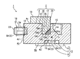
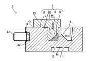
例えば、図6に示すように、プリズム18に連設されている鍔部19の右端部を、プリズム配置用凹部16の右内側面16aよりも右方に延出させることによって、プリズム18の配置の容易化および安定化を図るようにしてもよい。
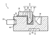
また、図7に示すように、接着剤20を、プリズム配置用凹部16とプリズム18との間に、満遍なく(凹部16の全内面にわたって)充填させるとともに、鍔部19と上端面4cとの間にも充填させることによって、プリズム18の接着力の増大を図ってもよい。
さらに、図8に示すように、第1の変形例と第2の変形例を組み合わせてもよいことは勿論である。
(第1の変形例)
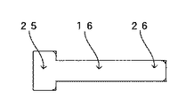
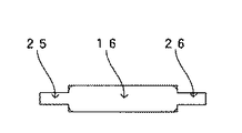
例えば、図13に示すように、第1の気泡滞留防止用凹部25および第2の気泡滞留防止用凹部26を、ともに、プリズム配置用凹部16よりもレンズ整列方向に直交する方向における一方(図13における上方)に大きく形成するようにしてもよい。
また、図14に示すように、第1の気泡滞留防止用凹部25を、プリズム配置用凹部16よりもレンズ整列方向に直交する方向における両方向(図14における上下方向)に大きく形成し、一方、第2の気泡滞留防止用凹部26を、プリズム配置用凹部16よりも同方向に小さく形成してもよい。
さらに、図15に示すように、第1の気泡滞留防止用凹部25および第2の気泡滞留防止用凹部26を、ともに、プリズム配置用凹部16よりもレンズ整列方向に直交する方向における両方向(図15における上下方向)に小さく形成してもよい。
(第1の変形例)
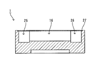
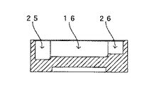
例えば、図20に示すように、第1の気泡滞留防止用凹部25および第2の気泡滞留防止用凹部26を、プリズム配置用凹部16よりも浅く形成してもよい。
また、図21に示すように、第1の気泡滞留防止用凹部25を、プリズム配置用凹部16よりも深く形成し、一方、第2の気泡滞留防止用凹部26を、プリズム配置用凹部16よりも浅く形成してもよい。
3 光電変換装置
4 レンズアレイ本体
5 光ファイバ
7 発光素子
8 受光素子
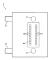
11 第1のレンズ面
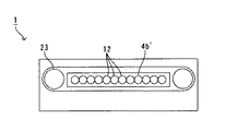
12 第2のレンズ面
13 第3のレンズ面
14 全反射面
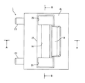
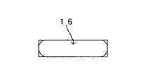
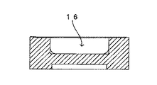
16 プリズム配置用凹部
17 反射/透過層
18 プリズム
20 接着剤
25 第1の気泡滞留防止用凹部
26 第2の気泡滞留防止用凹部
27 流入防止用凹縁部
Claims (4)
- 複数の発光素子が整列形成されるとともに前記複数の発光素子の少なくとも1つから発光された光をモニタするためのモニタ光を受光する少なくとも1つの受光素子が形成された光電変換装置と、光伝送体との間に配置され、前記複数の発光素子と前記光伝送体の端面とを光学的に結合可能とされたレンズアレイであって、
レンズアレイ本体における前記光電変換装置側の第1の面に、前記複数の発光素子に対応する所定の整列方向に整列するように形成され、前記複数の発光素子ごとに発光された光がそれぞれ入射する複数の第1のレンズ面と、
前記第1の面に前記整列方向に直交する方向において隣位する前記レンズアレイ本体における前記光伝送体側の第2の面に、前記整列方向に沿って整列するように形成され、前記複数の第1のレンズ面にそれぞれ入射した前記複数の発光素子ごとの光を、前記光伝送体の端面に向けてそれぞれ出射させる複数の第2のレンズ面と、
前記第1の面における前記複数の第1のレンズ面に対して前記第2の面側の位置に形成され、前記レンズアレイ本体の内部側から入射した前記モニタ光を前記受光素子に向けて出射させる少なくとも1つの第3のレンズ面と、
前記レンズアレイ本体における前記第1の面と反対側の第3の面に前記複数の第1のレンズ面に対向するように凹入形成された凹部の内斜面であって、前記複数の第1のレンズ面に対向するように形成され、前記複数の第1のレンズ面に入射した前記複数の発光素子ごとの光を前記複数の第2のレンズ面側に向けて全反射させる全反射面と、
前記第3の面における前記全反射面が形成されている前記凹部の前記第2の面側の隣の位置であって前記第3のレンズ面に対向する位置に、前記複数の第1のレンズ面と前記複数の第2のレンズ面とを結ぶ光路上に位置するように凹入形成されたプリズム配置用凹部と、
このプリズム配置用凹部内に配置され、前記複数の第2のレンズ面側に向かって進行する前記複数の発光素子ごとの光の光路を形成するプリズムと、
このプリズムにおける前記複数の発光素子ごとの光の入射面上に配置され、前記全反射面によって全反射された前記複数の発光素子ごとの光を、所定の反射率で前記第3のレンズ面側に反射させるとともに所定の透過率で前記第2のレンズ面側に透過させ、その際に、前記複数の発光素子ごとの光の少なくとも1つを前記モニタ光として反射させる反射/透過層と、
前記プリズム配置用凹部と前記プリズムとの間に充填され、前記プリズムを前記プリズム配置用凹部内に接着する透光性の接着剤と、
前記第3の面に、前記プリズム配置用凹部に対して前記整列方向の一方において連通されるとともに、前記複数の発光素子ごとの光の光路上から逸脱するように凹入形成され、前記プリズムの接着時における前記プリズム配置用凹部と前記プリズムとの間の前記複数の発光素子ごとの光の光路上への前記接着剤の気泡の滞留を防止するための第1の気泡滞留防止用凹部と、
前記第3の面に、前記プリズム配置用凹部に対して前記整列方向の他方において連通されるとともに、前記複数の発光素子ごとの光の光路上から逸脱するように凹入形成され、前記接着剤の気泡の滞留を防止するための第2の気泡滞留防止用凹部と、
前記第3の面に、前記プリズム配置用凹部、前記第1の気泡滞留防止用凹部および前記第2の気泡滞留防止用凹部のそれぞれの開口を包囲するように凹入形成されるとともに前記全反射面が形成されている凹部の開口に到達しない形状に形成され、前記プリズムの接着時における前記接着剤の前記全反射面上への流入を防止するための接着剤流入防止用凹縁部と
を備えたことを特徴とするレンズアレイ。 - 請求項1に記載のプリズム配置用凹部内に、請求項1に記載のプリズムを請求項1に記載の接着剤を介して接着することによって、請求項1に記載のレンズアレイを製造すること
を特徴とするレンズアレイの製造方法。 - 前記プリズム配置用凹部内に前記プリズムを配置した状態で、前記接着剤を、請求項1に記載の第1の気泡滞留防止用凹部および第2の気泡滞留防止用凹部の一方から注入して他方に向かって流動させながら、前記プリズム配置用凹部と前記プリズムとの間に充填させること
を特徴とする請求項2に記載のレンズアレイの製造方法。 - 前記プリズム配置用凹部内に前記接着剤を配置した状態で、前記プリズムを前記プリズム配置用凹部内に配置することによって、前記接着剤を、前記第1の気泡滞留防止用凹部および第2の気泡滞留防止用凹部に向かって流動させながら、前記プリズム配置用凹部と前記プリズムとの間に充填させること
を特徴とする請求項2に記載のレンズアレイの製造方法。
Priority Applications (5)
| Application Number | Priority Date | Filing Date | Title |
|---|---|---|---|
| JP2011233757A JP6089354B2 (ja) | 2011-10-25 | 2011-10-25 | レンズアレイおよびその製造方法 |
| TW101137901A TW201329552A (zh) | 2011-10-25 | 2012-10-15 | 透鏡陣列及其製造方法 |
| CN201280052224.6A CN104024901B (zh) | 2011-10-25 | 2012-10-24 | 透镜阵列以及其制造方法 |
| US14/352,976 US9110256B2 (en) | 2011-10-25 | 2012-10-24 | Lens array and manufacturing method thereof |
| PCT/JP2012/077475 WO2013062004A1 (ja) | 2011-10-25 | 2012-10-24 | レンズアレイおよびその製造方法 |
Applications Claiming Priority (1)
| Application Number | Priority Date | Filing Date | Title |
|---|---|---|---|
| JP2011233757A JP6089354B2 (ja) | 2011-10-25 | 2011-10-25 | レンズアレイおよびその製造方法 |
Publications (2)
| Publication Number | Publication Date |
|---|---|
| JP2013092605A JP2013092605A (ja) | 2013-05-16 |
| JP6089354B2 true JP6089354B2 (ja) | 2017-03-08 |
Family
ID=48167831
Family Applications (1)
| Application Number | Title | Priority Date | Filing Date |
|---|---|---|---|
| JP2011233757A Expired - Fee Related JP6089354B2 (ja) | 2011-10-25 | 2011-10-25 | レンズアレイおよびその製造方法 |
Country Status (5)
| Country | Link |
|---|---|
| US (1) | US9110256B2 (ja) |
| JP (1) | JP6089354B2 (ja) |
| CN (1) | CN104024901B (ja) |
| TW (1) | TW201329552A (ja) |
| WO (1) | WO2013062004A1 (ja) |
Families Citing this family (14)
| Publication number | Priority date | Publication date | Assignee | Title |
|---|---|---|---|---|
| JP5702596B2 (ja) * | 2010-10-28 | 2015-04-15 | 株式会社エンプラス | レンズアレイおよびこれを備えた光モジュール |
| US9487562B2 (en) | 2011-06-17 | 2016-11-08 | President And Fellows Of Harvard College | Stabilized polypeptides as regulators of RAB GTPase function |
| TWI578051B (zh) * | 2013-03-07 | 2017-04-11 | 鴻海精密工業股份有限公司 | 光連接器 |
| JP6011908B2 (ja) * | 2012-03-16 | 2016-10-25 | 株式会社エンプラス | 光レセプタクルおよびこれを備えた光モジュール |
| JP6205194B2 (ja) * | 2013-07-08 | 2017-09-27 | 株式会社エンプラス | 光レセプタクルおよび光モジュール |
| CN104345400A (zh) * | 2013-07-26 | 2015-02-11 | 鸿富锦精密工业(深圳)有限公司 | 光耦合模块、光电转换装置及光纤耦合连接器 |
| KR102252682B1 (ko) * | 2014-09-01 | 2021-05-18 | 한국전자통신연구원 | 다채널 광모듈 장치 및 그것의 제조 방법 |
| JP6402029B2 (ja) * | 2014-12-25 | 2018-10-10 | 株式会社エンプラス | 測定方法 |
| US10222555B2 (en) * | 2017-01-10 | 2019-03-05 | International Business Machines Corporation | Integrated optoelectronic chip and lens array |
| JP2019008243A (ja) * | 2017-06-28 | 2019-01-17 | 株式会社エンプラス | 光レセプタクルおよび光モジュール |
| JP6943660B2 (ja) * | 2017-07-14 | 2021-10-06 | 株式会社エンプラス | 光レセプタクルおよび光モジュール |
| CN107589488A (zh) * | 2017-09-25 | 2018-01-16 | 中航海信光电技术有限公司 | 一种透镜光纤阵列及并行光收发模块 |
| KR102004358B1 (ko) * | 2018-06-28 | 2019-10-01 | 옵티시스 주식회사 | 광 커넥터 |
| JP6675701B1 (ja) | 2019-11-13 | 2020-04-01 | 先端フォトニクス株式会社 | 光学部品及びアイソレータ |
Family Cites Families (12)
| Publication number | Priority date | Publication date | Assignee | Title |
|---|---|---|---|---|
| JPH02281211A (ja) * | 1989-04-21 | 1990-11-16 | Matsushita Electric Ind Co Ltd | 光コリメータおよび光結合部品 |
| US5500523A (en) * | 1990-09-21 | 1996-03-19 | Nippon Sheet Glass Co. Ltd. | Optical information transmitting device and method of manufacturing same |
| JP2001356246A (ja) * | 2000-06-13 | 2001-12-26 | Oki Electric Ind Co Ltd | 光モジュールおよびその製造方法 |
| JP2005269108A (ja) * | 2004-03-17 | 2005-09-29 | Nippon Sheet Glass Co Ltd | ライン照明装置およびライン照明装置を組み込んだ画像読取装置 |
| JP2006017885A (ja) | 2004-06-30 | 2006-01-19 | Fuji Xerox Co Ltd | 導波路フィルム型光モジュール、光導波路フィルム及びその製造方法 |
| JP2007150643A (ja) * | 2005-11-28 | 2007-06-14 | Sony Corp | 固体撮像素子、固体撮像素子の駆動方法および撮像装置 |
| JP2007166299A (ja) * | 2005-12-14 | 2007-06-28 | Sony Corp | 固体撮像素子、色分解撮像光学系及び撮像装置 |
| JP4914638B2 (ja) * | 2006-04-28 | 2012-04-11 | オリンパス株式会社 | 内視鏡、内視鏡装置、内視鏡の組み立て方法、内視鏡装置の組み立て方法 |
| JP2009058747A (ja) * | 2007-08-31 | 2009-03-19 | Fuji Xerox Co Ltd | 光電子回路基板および光電子回路基板の検査装置 |
| JP5185895B2 (ja) * | 2009-07-29 | 2013-04-17 | パナソニック株式会社 | 光電変換サブマウント基板及びその製造方法 |
| JP5485686B2 (ja) * | 2009-12-25 | 2014-05-07 | 株式会社エンプラス | レンズアレイおよびこれを備えた光モジュール |
| CN102667565B (zh) * | 2009-12-22 | 2015-05-13 | 恩普乐股份有限公司 | 透镜阵列以及具备该透镜阵列的光学模块 |
-
2011
- 2011-10-25 JP JP2011233757A patent/JP6089354B2/ja not_active Expired - Fee Related
-
2012
- 2012-10-15 TW TW101137901A patent/TW201329552A/zh not_active IP Right Cessation
- 2012-10-24 US US14/352,976 patent/US9110256B2/en active Active
- 2012-10-24 WO PCT/JP2012/077475 patent/WO2013062004A1/ja active Application Filing
- 2012-10-24 CN CN201280052224.6A patent/CN104024901B/zh active Active
Also Published As
| Publication number | Publication date |
|---|---|
| TW201329552A (zh) | 2013-07-16 |
| TWI563305B (ja) | 2016-12-21 |
| US20140270662A1 (en) | 2014-09-18 |
| CN104024901A (zh) | 2014-09-03 |
| CN104024901B (zh) | 2016-05-25 |
| US9110256B2 (en) | 2015-08-18 |
| JP2013092605A (ja) | 2013-05-16 |
| WO2013062004A1 (ja) | 2013-05-02 |
Similar Documents
| Publication | Publication Date | Title |
|---|---|---|
| JP6089354B2 (ja) | レンズアレイおよびその製造方法 | |
| WO2011077723A1 (ja) | レンズアレイおよびこれを備えた光モジュール | |
| US9423293B2 (en) | Optical receptacle and optical module | |
| US9310530B2 (en) | Lens array and optical module provided therewith | |
| JP5485686B2 (ja) | レンズアレイおよびこれを備えた光モジュール | |
| TWI576629B (zh) | 光插座及具備其的光模組 | |
| TWI619980B (zh) | 透鏡陣列及具備它的光學模組 | |
| TWI491944B (zh) | Light module | |
| TWI536045B (zh) | Lens array and manufacturing method thereof | |
| US20080131050A1 (en) | Manufacturing method of optical-electrical substrate and optical-electrical substrate | |
| KR20110028273A (ko) | 광 스플리터 장치 | |
| WO2013140922A1 (ja) | 光レセプタクルおよびこれを備えた光モジュール | |
| KR20100112190A (ko) | 회로 보드 실장 광학 도파관용 광학 탭 | |
| US20190094475A1 (en) | Optical receptacle, optical module, and method for manufacturing optical module | |
| JP2012194454A (ja) | レンズアレイおよびこれを備えた光モジュール | |
| TWI579610B (zh) | 光插座及具備其的光模組 | |
| JP2012163904A (ja) | 光通信モジュール及び光結合部材 | |
| JP2011141478A (ja) | レンズアレイおよびこれを備えた光モジュール | |
| JP2013057720A (ja) | 光モジュール | |
| JP2017049613A (ja) | レンズアレイおよびこれを備えた光モジュール | |
| WO2016147300A1 (ja) | 光導波路及びその製造方法、その光導波路を用いた光デバイス | |
| JP5749578B2 (ja) | レンズアレイおよびこれを備えた光モジュール | |
| JP2007156114A (ja) | 光信号入出力装置の製造方法 | |
| JP5758725B2 (ja) | レンズアレイおよびこれを備えた光モジュール | |
| JP5749577B2 (ja) | レンズアレイおよびこれを備えた光モジュール |
Legal Events
| Date | Code | Title | Description |
|---|---|---|---|
| A621 | Written request for application examination |
Free format text: JAPANESE INTERMEDIATE CODE: A621 Effective date: 20140919 |
|
| A131 | Notification of reasons for refusal |
Free format text: JAPANESE INTERMEDIATE CODE: A131 Effective date: 20150915 |
|
| A521 | Request for written amendment filed |
Free format text: JAPANESE INTERMEDIATE CODE: A523 Effective date: 20151116 |
|
| A131 | Notification of reasons for refusal |
Free format text: JAPANESE INTERMEDIATE CODE: A131 Effective date: 20160517 |
|
| A521 | Request for written amendment filed |
Free format text: JAPANESE INTERMEDIATE CODE: A523 Effective date: 20160714 |
|
| TRDD | Decision of grant or rejection written | ||
| A01 | Written decision to grant a patent or to grant a registration (utility model) |
Free format text: JAPANESE INTERMEDIATE CODE: A01 Effective date: 20161108 |
|
| A61 | First payment of annual fees (during grant procedure) |
Free format text: JAPANESE INTERMEDIATE CODE: A61 Effective date: 20161207 |
|
| A61 | First payment of annual fees (during grant procedure) |
Free format text: JAPANESE INTERMEDIATE CODE: A61 Effective date: 20170120 |
|
| R150 | Certificate of patent or registration of utility model |
Ref document number: 6089354 Country of ref document: JP Free format text: JAPANESE INTERMEDIATE CODE: R150 |
|
| R250 | Receipt of annual fees |
Free format text: JAPANESE INTERMEDIATE CODE: R250 |
|
| R250 | Receipt of annual fees |
Free format text: JAPANESE INTERMEDIATE CODE: R250 |
|
| LAPS | Cancellation because of no payment of annual fees |
