JP6019415B2 - Sensor device - Google Patents

Sensor device Download PDF

Info

Publication number
JP6019415B2
JP6019415B2 JP2014503445A JP2014503445A JP6019415B2 JP 6019415 B2 JP6019415 B2 JP 6019415B2 JP 2014503445 A JP2014503445 A JP 2014503445A JP 2014503445 A JP2014503445 A JP 2014503445A JP 6019415 B2 JP6019415 B2 JP 6019415B2
Authority
JP
Japan
Prior art keywords
flow path
sensor device
aggregate
region
metal layer
Prior art date
Legal status (The legal status is an assumption and is not a legal conclusion. Google has not performed a legal analysis and makes no representation as to the accuracy of the status listed.)
Active
Application number
JP2014503445A
Other languages
Japanese (ja)
Other versions
JPWO2013132761A1 (en
Inventor
雄介 北川
雄介 北川
橋本谷 磨志
磨志 橋本谷
福島 奨
奨 福島
Current Assignee (The listed assignees may be inaccurate. Google has not performed a legal analysis and makes no representation or warranty as to the accuracy of the list.)
Panasonic Intellectual Property Management Co Ltd
Original Assignee
Panasonic Intellectual Property Management Co Ltd
Priority date (The priority date is an assumption and is not a legal conclusion. Google has not performed a legal analysis and makes no representation as to the accuracy of the date listed.)
Filing date
Publication date
Application filed by Panasonic Intellectual Property Management Co Ltd filed Critical Panasonic Intellectual Property Management Co Ltd
Publication of JPWO2013132761A1 publication Critical patent/JPWO2013132761A1/en
Application granted granted Critical
Publication of JP6019415B2 publication Critical patent/JP6019415B2/en
Active legal-status Critical Current
Anticipated expiration legal-status Critical

Links

Images

Classifications

    • GPHYSICS
    • G01MEASURING; TESTING
    • G01NINVESTIGATING OR ANALYSING MATERIALS BY DETERMINING THEIR CHEMICAL OR PHYSICAL PROPERTIES
    • G01N33/00Investigating or analysing materials by specific methods not covered by groups G01N1/00 - G01N31/00
    • G01N33/48Biological material, e.g. blood, urine; Haemocytometers
    • G01N33/50Chemical analysis of biological material, e.g. blood, urine; Testing involving biospecific ligand binding methods; Immunological testing
    • G01N33/53Immunoassay; Biospecific binding assay; Materials therefor
    • G01N33/543Immunoassay; Biospecific binding assay; Materials therefor with an insoluble carrier for immobilising immunochemicals
    • G01N33/54366Apparatus specially adapted for solid-phase testing
    • G01N33/54373Apparatus specially adapted for solid-phase testing involving physiochemical end-point determination, e.g. wave-guides, FETS, gratings
    • BPERFORMING OPERATIONS; TRANSPORTING
    • B01PHYSICAL OR CHEMICAL PROCESSES OR APPARATUS IN GENERAL
    • B01LCHEMICAL OR PHYSICAL LABORATORY APPARATUS FOR GENERAL USE
    • B01L3/00Containers or dishes for laboratory use, e.g. laboratory glassware; Droppers
    • B01L3/50Containers for the purpose of retaining a material to be analysed, e.g. test tubes
    • B01L3/502Containers for the purpose of retaining a material to be analysed, e.g. test tubes with fluid transport, e.g. in multi-compartment structures
    • B01L3/5027Containers for the purpose of retaining a material to be analysed, e.g. test tubes with fluid transport, e.g. in multi-compartment structures by integrated microfluidic structures, i.e. dimensions of channels and chambers are such that surface tension forces are important, e.g. lab-on-a-chip
    • B01L3/502761Containers for the purpose of retaining a material to be analysed, e.g. test tubes with fluid transport, e.g. in multi-compartment structures by integrated microfluidic structures, i.e. dimensions of channels and chambers are such that surface tension forces are important, e.g. lab-on-a-chip specially adapted for handling suspended solids or molecules independently from the bulk fluid flow, e.g. for trapping or sorting beads, for physically stretching molecules
    • GPHYSICS
    • G01MEASURING; TESTING
    • G01NINVESTIGATING OR ANALYSING MATERIALS BY DETERMINING THEIR CHEMICAL OR PHYSICAL PROPERTIES
    • G01N21/00Investigating or analysing materials by the use of optical means, i.e. using sub-millimetre waves, infrared, visible or ultraviolet light
    • G01N21/01Arrangements or apparatus for facilitating the optical investigation
    • G01N21/03Cuvette constructions
    • G01N21/05Flow-through cuvettes
    • GPHYSICS
    • G01MEASURING; TESTING
    • G01NINVESTIGATING OR ANALYSING MATERIALS BY DETERMINING THEIR CHEMICAL OR PHYSICAL PROPERTIES
    • G01N21/00Investigating or analysing materials by the use of optical means, i.e. using sub-millimetre waves, infrared, visible or ultraviolet light
    • G01N21/17Systems in which incident light is modified in accordance with the properties of the material investigated
    • G01N21/41Refractivity; Phase-affecting properties, e.g. optical path length
    • GPHYSICS
    • G01MEASURING; TESTING
    • G01NINVESTIGATING OR ANALYSING MATERIALS BY DETERMINING THEIR CHEMICAL OR PHYSICAL PROPERTIES
    • G01N21/00Investigating or analysing materials by the use of optical means, i.e. using sub-millimetre waves, infrared, visible or ultraviolet light
    • G01N21/17Systems in which incident light is modified in accordance with the properties of the material investigated
    • G01N21/55Specular reflectivity
    • G01N21/552Attenuated total reflection
    • G01N21/553Attenuated total reflection and using surface plasmons
    • GPHYSICS
    • G01MEASURING; TESTING
    • G01NINVESTIGATING OR ANALYSING MATERIALS BY DETERMINING THEIR CHEMICAL OR PHYSICAL PROPERTIES
    • G01N21/00Investigating or analysing materials by the use of optical means, i.e. using sub-millimetre waves, infrared, visible or ultraviolet light
    • G01N21/75Systems in which material is subjected to a chemical reaction, the progress or the result of the reaction being investigated
    • G01N21/77Systems in which material is subjected to a chemical reaction, the progress or the result of the reaction being investigated by observing the effect on a chemical indicator
    • BPERFORMING OPERATIONS; TRANSPORTING
    • B01PHYSICAL OR CHEMICAL PROCESSES OR APPARATUS IN GENERAL
    • B01LCHEMICAL OR PHYSICAL LABORATORY APPARATUS FOR GENERAL USE
    • B01L2200/00Solutions for specific problems relating to chemical or physical laboratory apparatus
    • B01L2200/06Fluid handling related problems
    • B01L2200/0647Handling flowable solids, e.g. microscopic beads, cells, particles
    • B01L2200/0668Trapping microscopic beads
    • BPERFORMING OPERATIONS; TRANSPORTING
    • B01PHYSICAL OR CHEMICAL PROCESSES OR APPARATUS IN GENERAL
    • B01LCHEMICAL OR PHYSICAL LABORATORY APPARATUS FOR GENERAL USE
    • B01L2300/00Additional constructional details
    • B01L2300/06Auxiliary integrated devices, integrated components
    • B01L2300/069Absorbents; Gels to retain a fluid
    • BPERFORMING OPERATIONS; TRANSPORTING
    • B01PHYSICAL OR CHEMICAL PROCESSES OR APPARATUS IN GENERAL
    • B01LCHEMICAL OR PHYSICAL LABORATORY APPARATUS FOR GENERAL USE
    • B01L2400/00Moving or stopping fluids
    • B01L2400/04Moving fluids with specific forces or mechanical means
    • B01L2400/0403Moving fluids with specific forces or mechanical means specific forces
    • B01L2400/043Moving fluids with specific forces or mechanical means specific forces magnetic forces

Landscapes

  • Health & Medical Sciences (AREA)
  • Chemical & Material Sciences (AREA)
  • Physics & Mathematics (AREA)
  • Life Sciences & Earth Sciences (AREA)
  • Immunology (AREA)
  • Analytical Chemistry (AREA)
  • General Health & Medical Sciences (AREA)
  • Biochemistry (AREA)
  • General Physics & Mathematics (AREA)
  • Pathology (AREA)
  • Engineering & Computer Science (AREA)
  • Hematology (AREA)
  • Chemical Kinetics & Catalysis (AREA)
  • Biomedical Technology (AREA)
  • Urology & Nephrology (AREA)
  • Molecular Biology (AREA)
  • Fluid Mechanics (AREA)
  • Plasma & Fusion (AREA)
  • Dispersion Chemistry (AREA)
  • Clinical Laboratory Science (AREA)
  • Biotechnology (AREA)
  • Cell Biology (AREA)
  • Microbiology (AREA)
  • Food Science & Technology (AREA)
  • Medicinal Chemistry (AREA)
  • Investigating Or Analysing Materials By Optical Means (AREA)

Description

本発明は、例えば、ウィルス等の検知に使用できるセンサデバイスに関する。   The present invention relates to a sensor device that can be used for detecting, for example, viruses.

図22は、例えば、ウィルス検知等に使用可能な特許文献1に開示されているセンサデバイス600の断面図である。センサデバイス600は、プリズム601と、プリズム601の下面に配置された表面の平坦な金属層602と、金属層602の下面に配置された表面の平坦な所定の誘電率を有する絶縁層603と、絶縁層603の下面に固定されたアクセプタ604とを有している。   FIG. 22 is a cross-sectional view of a sensor device 600 disclosed in Patent Document 1 that can be used for virus detection or the like, for example. The sensor device 600 includes a prism 601, a flat metal layer 602 disposed on the lower surface of the prism 601, an insulating layer 603 having a predetermined flat dielectric constant disposed on the lower surface of the metal layer 602, And an acceptor 604 fixed to the lower surface of the insulating layer 603.

金属層602と絶縁層603との界面には、電子の疎密波である表面プラズモン波が存在している。プリズム601側上方には光源605が配置され、光源605からプリズム601へP偏光された光を全反射条件で入射する。このとき、金属層602と絶縁層603との表面にはエバネセント波が生じている。金属層602において全反射された光は、検波部606において受光され、光の強度が検出される。   At the interface between the metal layer 602 and the insulating layer 603, a surface plasmon wave that is an electron density wave exists. A light source 605 is arranged above the prism 601 side, and P-polarized light is incident on the prism 601 from the light source 605 under total reflection conditions. At this time, evanescent waves are generated on the surfaces of the metal layer 602 and the insulating layer 603. The light totally reflected by the metal layer 602 is received by the detection unit 606, and the intensity of the light is detected.

ここで、エバネセント波と表面プラズモン波との波数が一致する波数整合条件が満たされると、光源605から供給される光のエネルギーは表面プラズモン波の励起に利用され、反射光の強度が減少する。波数整合条件は、光源605から供給される光の入射角に依存する。したがって、入射角を変化させて検波部606で反射光強度を検出すると、ある入射角において、反射光の強度が減少する。   Here, when the wave number matching condition in which the wave numbers of the evanescent wave and the surface plasmon wave match is satisfied, the energy of the light supplied from the light source 605 is used for excitation of the surface plasmon wave, and the intensity of the reflected light decreases. The wave number matching condition depends on the incident angle of light supplied from the light source 605. Accordingly, when the reflected light intensity is detected by the detection unit 606 while changing the incident angle, the intensity of the reflected light decreases at a certain incident angle.

反射光の強度が最小となる角度である共鳴角は、絶縁層603の誘電率に依存している。試料中の被測定物質であるアナライトとアクセプタ604とが特異的に結合して生成された特異的結合物が絶縁層603の下面に構成されると、絶縁層603の誘電率が変化し、これに応じて、共鳴角が変化する。したがって、共鳴角の変化をモニタリングすることにより、アナライトとアクセプタ604との特異的結合反応の結合の強さや結合の速さなどを検知することが可能となる。   The resonance angle, which is the angle at which the intensity of the reflected light is minimized, depends on the dielectric constant of the insulating layer 603. When the specific binding substance generated by specifically binding the analyte as the substance to be measured in the sample and the acceptor 604 is formed on the lower surface of the insulating layer 603, the dielectric constant of the insulating layer 603 changes, In accordance with this, the resonance angle changes. Therefore, by monitoring the change in the resonance angle, it is possible to detect the strength of binding and the speed of binding in the specific binding reaction between the analyte and the acceptor 604.

特開2005−181296号公報JP 2005-181296 A

センサデバイスは、アナライトを含む試料が流れるように構成されてかつ担体が配置されるように構成された流路と、流路に設けられた金属層とを備える。担体の表面にはアナライトと特異的結合して凝集体を生成する複数のアクセプタが固定されるように構成されている。流路は、アナライトが偏在するように構成された凝集体トラップ部を有する。   The sensor device includes a channel configured to allow a sample containing an analyte to flow and a carrier to be disposed, and a metal layer provided in the channel. A plurality of acceptors that specifically bind to the analyte and generate aggregates are immobilized on the surface of the carrier. The flow path has an aggregate trap part configured so that the analyte is unevenly distributed.

このセンサデバイスは簡単な構成で高い検出感度を有する。   This sensor device has a high detection sensitivity with a simple configuration.

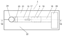
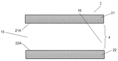
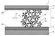
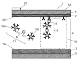
図1Aは本発明の実施の形態1におけるセンサデバイスの上面図である。FIG. 1A is a top view of the sensor device according to Embodiment 1 of the present invention. 図1Bは図1Aに示すセンサデバイスの線1B−1Bにおける断面図である。1B is a cross-sectional view taken along line 1B-1B of the sensor device shown in FIG. 1A. 図2Aは実施の形態1におけるセンサデバイスの側断面図である。FIG. 2A is a sectional side view of the sensor device according to Embodiment 1. 図2Bは図2Aに示すセンサデバイスの上面断面図である。2B is a top cross-sectional view of the sensor device shown in FIG. 2A. 図3は実施の形態1におけるセンサデバイスのアクセプタとアナライトの特異的結合を示す概念図である。FIG. 3 is a conceptual diagram showing specific binding between the acceptor and the analyte of the sensor device in the first embodiment. 図4Aは実施の形態1におけるセンサデバイスの側断面図である。4A is a side sectional view of the sensor device according to Embodiment 1. FIG. 図4Bは実施の形態1におけるセンサデバイスの側断面図である。FIG. 4B is a sectional side view of the sensor device according to Embodiment 1. 図5は実施の形態1におけるセンサデバイスの電磁界シミュレーション解析モデルの概念図である。FIG. 5 is a conceptual diagram of an electromagnetic field simulation analysis model of the sensor device in the first embodiment. 図6は実施の形態1におけるセンサデバイスの電磁気シミュレーションの解析結果を示す図である。FIG. 6 is a diagram showing an analysis result of the electromagnetic simulation of the sensor device in the first embodiment. 図7Aは実施の形態1におけるセンサデバイスの側断面図である。FIG. 7A is a side sectional view of the sensor device according to Embodiment 1. 図7Bは実施の形態1におけるセンサデバイスの側断面図である。FIG. 7B is a sectional side view of the sensor device according to Embodiment 1. 図8Aは実施の形態1におけるセンサデバイスの側断面図である。FIG. 8A is a side sectional view of the sensor device according to Embodiment 1. 図8Bは実施の形態1におけるセンサデバイスの側断面図である。FIG. 8B is a side sectional view of the sensor device according to Embodiment 1. 図9は実施の形態1におけるセンサデバイスの側断面図である。FIG. 9 is a side sectional view of the sensor device according to the first exemplary embodiment. 図10は実施の形態1におけるセンサデバイスの側断面図である。FIG. 10 is a side sectional view of the sensor device according to the first embodiment. 図11は実施の形態1におけるセンサデバイスの側断面図である。FIG. 11 is a sectional side view of the sensor device according to the first embodiment. 図12は実施の形態1におけるセンサデバイスの側断面図である。FIG. 12 is a side sectional view of the sensor device according to the first embodiment. 図13Aは本発明の実施の形態2におけるセンサデバイスの上面断面図である。FIG. 13A is a top cross-sectional view of the sensor device according to Embodiment 2 of the present invention. 図13Bは実施の形態2における他のセンサデバイスの上面断面図である。FIG. 13B is a top cross-sectional view of another sensor device according to Embodiment 2. 図14Aは実施の形態2におけるセンサデバイスの側断面図である。FIG. 14A is a side sectional view of the sensor device according to the second exemplary embodiment. 図14Bは図14Aに示すセンサデバイスの上面断面図である。14B is a top cross-sectional view of the sensor device shown in FIG. 14A. 図15は凝集体の概念図である。FIG. 15 is a conceptual diagram of an aggregate. 図16Aは本発明の実施の形態3におけるセンサデバイスの側断面図である。FIG. 16A is a sectional side view of the sensor device according to Embodiment 3 of the present invention. 図16Bは図16Aに示すセンサデバイスの拡大図である。FIG. 16B is an enlarged view of the sensor device shown in FIG. 16A. 図17は実施の形態3におけるセンサデバイスにおける電界強度の分布を表わす図である。FIG. 17 is a diagram showing the distribution of electric field strength in the sensor device according to the third embodiment. 図18Aは本発明の実施の形態4におけるセンサデバイスの上面断面図である。FIG. 18A is a top cross-sectional view of a sensor device according to Embodiment 4 of the present invention. 図18Bは図18Aに示すセンサデバイスの線18B−18Bにおける側断面図である。18B is a side cross-sectional view of the sensor device shown in FIG. 18A taken along line 18B-18B. 図18Cは実施の形態4における他のセンサデバイスの上面断面図である。FIG. 18C is a top cross-sectional view of another sensor device according to Embodiment 4. 図18Dは図18Cに示すセンサデバイスの線18D−18Dにおける側断面図である。18D is a side cross-sectional view of the sensor device shown in FIG. 18C taken along line 18D-18D. 図19Aは本発明の実施の形態5におけるセンサデバイスの上面断面図である。FIG. 19A is a top cross-sectional view of a sensor device according to Embodiment 5 of the present invention. 図19Bは図19Aに示すセンサデバイスの線19B−19Bにおける側断面図である。19B is a cross-sectional side view of the sensor device shown in FIG. 19A taken along line 19B-19B. 図20Aは本発明の実施の形態6におけるセンサデバイスの上面断面図である。FIG. 20A is a top cross-sectional view of the sensor device according to the sixth embodiment of the present invention. 図20Bは図20Aに示すセンサデバイスの線20B−20Bにおける側断面図である。20B is a cross-sectional side view of the sensor device shown in FIG. 20A taken along line 20B-20B. 図21Aは本発明の実施の形態7におけるセンサデバイスの断面図である。FIG. 21A is a cross-sectional view of the sensor device according to Embodiment 7 of the present invention. 図21Bは実施の形態7におけるセンサデバイスの下面斜視図である。FIG. 21B is a bottom perspective view of the sensor device according to Embodiment 7. 図22は従来のセンサデバイスの断面図である。FIG. 22 is a cross-sectional view of a conventional sensor device.

(実施の形態1)
図1Aは本発明の実施の形態1におけるセンサデバイス1の上面図である。図1Bは図1Aに示すセンサデバイス1の線1B−1Bにおける断面図である。センサデバイス1はMIM(Metal Insulator Metal)型のセンサデバイスである。
(Embodiment 1)
FIG. 1A is a top view of sensor device 1 according to Embodiment 1 of the present invention. 1B is a cross-sectional view taken along line 1B-1B of the sensor device 1 shown in FIG. 1A. The sensor device 1 is a MIM (Metal Insulator Metal) type sensor device.

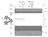
センサデバイス1は、試料を注入する注入口24と、注入された試料を一旦、貯留する貯留部25と、注入された試料をセンサ内に流す流路4と、流路4を流れて来た検査済みの試料を貯留する貯留部26と、流路4の少なくとも一部に設けられた金属層2、3を備えている。ユーザはスポイド27などにより、検査対象となる試料を注入口24から貯留部25に注入する。流路4は、センサデバイス1の上側に配置され金属層2を保持する保持部5と、センサデバイス1の下側に配置され金属層3を保持する保持部6と、側壁部21および側壁部22により構成されている。流路4内には、金属層2、3に挟まれた特定の領域18と、特定の領域18の前に配置された投入領域15と、領域18の後に配置された排出領域16が設けられている。貯留部25に貯留された試料は、毛細管現象等により流路4の投入領域15に投入される。流路4内に投入された試料は流路4内を矢印17の方向へ流れて領域18を経由して排出領域16から排出され貯留部26に貯留される。また、試料中の検体であるアナライトは流路4内の領域18にトラップされ検出される。このように、領域18はアナライトの凝集体をトラップする凝集体トラップ部として機能する。   The sensor device 1 has flowed through the flow path 4, the inlet 24 for injecting the sample, the storage unit 25 for temporarily storing the injected sample, the flow path 4 for flowing the injected sample into the sensor, and the like. A storage section 26 for storing the tested sample, and metal layers 2 and 3 provided in at least a part of the flow path 4 are provided. The user injects the sample to be inspected into the storage unit 25 from the injection port 24 using the spoid 27 or the like. The flow path 4 includes a holding portion 5 that is disposed on the upper side of the sensor device 1 and holds the metal layer 2, a holding portion 6 that is disposed on the lower side of the sensor device 1 and holds the metal layer 3, a side wall portion 21, and a side wall portion. 22. In the flow path 4, a specific region 18 sandwiched between the metal layers 2, 3, an input region 15 disposed in front of the specific region 18, and a discharge region 16 disposed after the region 18 are provided. ing. The sample stored in the storage unit 25 is input to the input region 15 of the flow path 4 by capillary action or the like. The sample put into the flow path 4 flows in the direction of the arrow 17 in the flow path 4, is discharged from the discharge area 16 via the area 18, and is stored in the storage section 26. In addition, the analyte that is the specimen in the sample is trapped in the region 18 in the flow path 4 and detected. Thus, the region 18 functions as an aggregate trap portion for trapping analyte aggregates.

センサデバイス1の動作について説明する。流路4内の金属層2および金属層3に挟まれた部分は検出部を構成する。図2Aと図2Bはそれぞれセンサデバイス1の主要部分を示す側断面図と上面断面図である。図2Aに示すように、金属層3は、流路4を介して金属層2に対向して金属層2の下方に配置されている。金属層2、3は金、銀等の金属で構成される。また、図2Bに示すように、側壁部21は流路4を挟んで側壁部22に対向して配置されている。金属層2の下面2Bは流路4の上面を構成し、金属層3の上面3Aは流路4の下面を構成し、側壁部21の側面21Aは流路4の第1の側面を構成し、側壁部22の側面22Aは流路4の第2の側面を構成する。このように、これら4つの面から流路4が形成されている。金属層2の下面2B、金属層3の上面3Aの少なくとも一方には複数の担体10がファンデルワールス力等の弱い力により物理的に吸着固定されている。担体10は、金属、樹脂等からなる物質の表面に固定された、検体であるアナライト8と特異的に結合する複数のアクセプタ7よりなる。   The operation of the sensor device 1 will be described. A portion sandwiched between the metal layer 2 and the metal layer 3 in the flow path 4 constitutes a detection unit. 2A and 2B are a side sectional view and a top sectional view showing the main part of the sensor device 1, respectively. As shown in FIG. 2A, the metal layer 3 is disposed below the metal layer 2 so as to face the metal layer 2 through the flow path 4. The metal layers 2 and 3 are made of a metal such as gold or silver. Further, as shown in FIG. 2B, the side wall portion 21 is disposed to face the side wall portion 22 with the flow path 4 interposed therebetween. The lower surface 2B of the metal layer 2 constitutes the upper surface of the channel 4, the upper surface 3A of the metal layer 3 constitutes the lower surface of the channel 4, and the side surface 21A of the side wall portion 21 constitutes the first side surface of the channel 4. The side surface 22 </ b> A of the side wall portion 22 constitutes the second side surface of the flow path 4. Thus, the flow path 4 is formed from these four surfaces. A plurality of carriers 10 are physically adsorbed and fixed to at least one of the lower surface 2B of the metal layer 2 and the upper surface 3A of the metal layer 3 by a weak force such as van der Waals force. The carrier 10 includes a plurality of acceptors 7 that specifically bind to an analyte 8 that is a specimen, which is fixed to the surface of a substance made of metal, resin, or the like.

金属、樹脂等からなる物質の大きさは、センサデバイス1の上方より入射される電磁波の波長の1/10以下であることが好ましい。物質の大きさは例えばその物質の径である。この波長は、流路4内の屈折率の影響を加味した波長を指している。金属、樹脂等からなる物質の大きさが入射される電磁波の波長の1/10以上の場合、ミー散乱の影響が強いが、1/10以下の場合、レイリー散乱の影響が強くなる。レイリー散乱はその散乱強度が物質の半径の−6乗に比例するため非常に小さく、散乱の影響がほぼ無視できるので、センサデバイス1の感度を向上させることができる。散乱の影響が大きい場合、光の直進性が失われ、観察光がうまく観察できない恐れがあるので、例えば、センサデバイス1の上方から入射する電磁波として可視光(特に、観察に用いる波長の500〜600nm)を用いた場合には、金属、樹脂等からなる物質の大きさは50〜60nm以下であることが好ましい。   The size of the substance made of metal, resin or the like is preferably 1/10 or less of the wavelength of the electromagnetic wave incident from above the sensor device 1. The size of the substance is, for example, the diameter of the substance. This wavelength indicates a wavelength that takes into account the influence of the refractive index in the flow path 4. When the size of the substance made of metal, resin, etc. is 1/10 or more of the wavelength of the incident electromagnetic wave, the influence of Mie scattering is strong, but when it is 1/10 or less, the influence of Rayleigh scattering is strong. Rayleigh scattering is very small because its scattering intensity is proportional to the -6th power of the radius of the substance, and the influence of scattering can be almost ignored, so that the sensitivity of the sensor device 1 can be improved. When the influence of scattering is large, the straightness of light is lost and the observation light may not be observed well. For example, visible light (especially having a wavelength of 500 to 500 nm used for observation) as electromagnetic waves incident from above the sensor device 1 may be observed. 600 nm), the size of the substance made of metal, resin or the like is preferably 50 to 60 nm or less.

センサデバイス1を使用する際には、試料62が投入領域15から流路4に投入されて充填され、充填された試料62は排出領域16から排出される。したがって、流路4中の試料62は実質的に金属層2、3で挟まれている。試料62は、アナライト8と非特異的検体9と媒質61とを含有する。媒質61は液体、ゲル等の流体よりなり、アナライト8と非特異的検体9とを運ぶ。   When the sensor device 1 is used, the sample 62 is charged into the flow path 4 from the input region 15 and filled, and the filled sample 62 is discharged from the discharge region 16. Therefore, the sample 62 in the flow path 4 is substantially sandwiched between the metal layers 2 and 3. The sample 62 contains the analyte 8, the nonspecific specimen 9, and the medium 61. The medium 61 is made of a fluid such as liquid or gel, and carries the analyte 8 and the nonspecific specimen 9.

金属層2は概ね100nm以下の厚みを有するので単体ではその形状を維持できない。金属層2の上面2Aは保持部5の下面5Bに固定され、その形状が保持される。金属層3は保持部6の上面6Aに固定されて保持される。   Since the metal layer 2 has a thickness of approximately 100 nm or less, the shape cannot be maintained alone. The upper surface 2A of the metal layer 2 is fixed to the lower surface 5B of the holding portion 5 and the shape thereof is held. The metal layer 3 is fixed and held on the upper surface 6A of the holding portion 6.

金属層2の上面2Aから電磁波91が入射する。電磁波91が可視光であり、金属層2が金よりなる場合には、金属層2は10nm〜45nmの範囲内の膜厚を有することが望ましい。   An electromagnetic wave 91 is incident from the upper surface 2A of the metal layer 2. When the electromagnetic wave 91 is visible light and the metal layer 2 is made of gold, the metal layer 2 preferably has a film thickness in the range of 10 nm to 45 nm.

金属層3が金よりなる場合には、金属層3は100nm以上の膜厚を有することが望ましい。金属層3の膜厚が100nm未満である場合には、入射された可視光である電磁波91は金属層3を透過し、流路4内へ反射される電磁波91の量が減る。   When the metal layer 3 is made of gold, the metal layer 3 desirably has a thickness of 100 nm or more. When the thickness of the metal layer 3 is less than 100 nm, the incident electromagnetic wave 91 that is visible light is transmitted through the metal layer 3 and the amount of the electromagnetic wave 91 reflected into the flow path 4 is reduced.

金属層2の上面2Aの上方、すなわち、金属層2について金属層3の反対の方向には電磁波源92が配置されている。電磁波源92は金属層2の上面2A上方から金属層2へ電磁波91を与える。   An electromagnetic wave source 92 is disposed above the upper surface 2A of the metal layer 2, that is, in the direction opposite to the metal layer 3 with respect to the metal layer 2. The electromagnetic wave source 92 applies an electromagnetic wave 91 from above the upper surface 2 </ b> A of the metal layer 2 to the metal layer 2.

なお、アクセプタ7とは、特定のアナライトと特異的結合をする捕捉体のことを指しており、例えば、抗体、受容体タンパク、アプタマー、ポルフィリン、モレキュラーインプリンティング技術により生成された高分子などを指す。   The acceptor 7 refers to a capturing body that specifically binds to a specific analyte. For example, an antibody, a receptor protein, an aptamer, a porphyrin, a polymer generated by a molecular imprinting technique, and the like. Point to.

なお、図1Bに示すように、貯留部25と流路4との間には、フィルター23が配置されていることが望ましい。フィルター23は試料中に混入したゴミなどの不要物を取り除く。   As shown in FIG. 1B, it is desirable that a filter 23 is disposed between the storage unit 25 and the flow path 4. The filter 23 removes unnecessary materials such as dust mixed in the sample.

以下、センサデバイス1の動作について説明する。実施の形態1においては、電磁波91は光であり、電磁波源92は光源である。   Hereinafter, the operation of the sensor device 1 will be described. In the first embodiment, the electromagnetic wave 91 is light, and the electromagnetic wave source 92 is a light source.

金属層2の上方から入射角θで上面2Aに与えられた電磁波の一部は、上面2A、下面2Bで反射されて、反射角−θの方向に金属層2から上方へ向けて伝搬していく。入射角θは、金属層2の上面の法線方向と電磁波の入射方向との間の角度である。金属層2の上方から入射された電磁波のうち、金属層2で反射されて金属層2から上方に向けて角度−θの方向へ伝搬していく電磁波を第1電磁波と呼ぶ。しかし、金属層2の上面2A、下面2Bで反射されなかった大部分の電磁波は、金属層2を透過して流路4を伝搬し、金属層3の上面3Aに到達する。金属層3の厚みが200nm以上と十分に厚いとき、金属層3の上方より到来した電磁波のすべては金属層3において反射され、再び金属層2の下面2Bに向けて流路4内を伝搬していく。そして、金属層2の下面2Bに到達した電磁波の一部は金属層2を透過し、金属層2から上方へ角度−θの方向で伝搬していく。以下、流路4から金属層2を透過し、金属層2から上方に向けて角度−θの方向へ伝搬していく電磁波を第2電磁波と呼ぶ。また、金属層2の下面2Bから到達し、金属層2を透過しなかった電磁波の大部分は金属層2の下面2B、上面2Aで反射され、再び、流路4内を下方へ向けて伝搬していく。金属層2の上方において、第1電磁波と第2電磁波とは干渉しあう。特に、整数mと、電磁波の真空中での波長λと、流路4の厚みdすなわち金属層2の下面と金属層3の上面との間隔dと、中空領域内の屈折率nと入射角θとで表される式1または式2の条件を満たす。間隔dが式1の条件を満たしたときには第1電磁波と第2電磁波とは弱めあい、間隔dが式2の条件を満たした時には第1電磁波と第2電磁波とは強めあう。   A part of the electromagnetic wave applied to the upper surface 2A at the incident angle θ from above the metal layer 2 is reflected by the upper surface 2A and the lower surface 2B and propagates upward from the metal layer 2 in the direction of the reflection angle −θ. Go. The incident angle θ is an angle between the normal direction of the upper surface of the metal layer 2 and the incident direction of the electromagnetic wave. Of the electromagnetic waves incident from above the metal layer 2, the electromagnetic waves reflected by the metal layer 2 and propagating upward from the metal layer 2 in the direction of the angle −θ are called first electromagnetic waves. However, most of the electromagnetic waves that are not reflected by the upper surface 2A and the lower surface 2B of the metal layer 2 pass through the metal layer 2 and propagate through the flow path 4 to reach the upper surface 3A of the metal layer 3. When the thickness of the metal layer 3 is sufficiently thick, such as 200 nm or more, all the electromagnetic waves that have arrived from above the metal layer 3 are reflected by the metal layer 3 and propagate through the channel 4 toward the lower surface 2B of the metal layer 2 again. To go. A part of the electromagnetic wave reaching the lower surface 2B of the metal layer 2 is transmitted through the metal layer 2 and propagates upward from the metal layer 2 at an angle of −θ. Hereinafter, an electromagnetic wave that passes through the metal layer 2 from the flow path 4 and propagates upward from the metal layer 2 in the direction of the angle −θ is referred to as a second electromagnetic wave. In addition, most of the electromagnetic waves that have arrived from the lower surface 2B of the metal layer 2 and did not pass through the metal layer 2 are reflected by the lower surface 2B and the upper surface 2A of the metal layer 2 and propagate again downward in the flow path 4. I will do it. Above the metal layer 2, the first electromagnetic wave and the second electromagnetic wave interfere with each other. In particular, the integer m, the wavelength λ of the electromagnetic wave in vacuum, the thickness d of the flow path 4, that is, the distance d between the lower surface of the metal layer 2 and the upper surface of the metal layer 3, the refractive index n and the incident angle in the hollow region The condition of the expression 1 or 2 expressed by θ is satisfied. When the distance d satisfies the condition of Expression 1, the first electromagnetic wave and the second electromagnetic wave are weakened, and when the distance d satisfies the condition of Expression 2, the first electromagnetic wave and the second electromagnetic wave are strengthened.

(m+1/2)×λ=2×n×d×cosθ …(式1)
m×λ=2×n×d×cosθ …(式2)
干渉条件は、金属層2および金属層3の形状の主に厚み、金属層2と金属層3の間の距離、金属層2の誘電率(屈折率)、金属層3の誘電率(屈折率)、流路4内の屈折率によって制御可能である。
(M + 1/2) × λ = 2 × n × d × cos θ (Formula 1)
m × λ = 2 × n × d × cos θ (Formula 2)
The interference conditions are mainly the thickness of the shape of the metal layer 2 and the metal layer 3, the distance between the metal layer 2 and the metal layer 3, the dielectric constant (refractive index) of the metal layer 2, and the dielectric constant (refractive index of the metal layer 3). ), And can be controlled by the refractive index in the flow path 4.

金属層2の上面2Aの上方には光等の電磁波93を検知する検知部94が配置される。電磁波源92から与えられた電磁波91をセンサデバイス1が受けた時に、センサデバイス1から反射又は輻射された光等の電磁波93を検知部94は受信する。なお、検知部94は必ずしも必要ではない。電磁波91が可視光の場合には、ユーザ自身の目で電磁波91の色の変化、強度を検知できる。これにより簡易で安価なセンサデバイス1を構築できる。   A detection unit 94 that detects an electromagnetic wave 93 such as light is disposed above the upper surface 2A of the metal layer 2. When the sensor device 1 receives the electromagnetic wave 91 applied from the electromagnetic wave source 92, the detection unit 94 receives the electromagnetic wave 93 such as light reflected or radiated from the sensor device 1. The detection unit 94 is not always necessary. When the electromagnetic wave 91 is visible light, the color change and intensity of the electromagnetic wave 91 can be detected by the user's own eyes. Thereby, a simple and inexpensive sensor device 1 can be constructed.

保持部5は電磁波91を金属層2へ効率良く供給するために、電磁波91を減衰させにくい材質で形成される。実施の形態1において、電磁波91は光なので、保持部5は光を効率的に透過させるガラスや透明プラスチック等の透明な材料で形成される。保持部5の厚みは機械強度的に許容できる範囲で、できるだけ小さい方が好ましい。   The holding unit 5 is formed of a material that hardly attenuates the electromagnetic wave 91 in order to efficiently supply the electromagnetic wave 91 to the metal layer 2. In the first embodiment, since the electromagnetic wave 91 is light, the holding unit 5 is formed of a transparent material such as glass or transparent plastic that efficiently transmits light. The thickness of the holding portion 5 is preferably as small as possible within a range that is acceptable in terms of mechanical strength.

センサデバイス1の感度を高くするためには、供給される光等の電磁波91が金属層3を透過しないことが好ましい。したがって、保持部6は光等の電磁波91を遮断する材料より形成されることが好ましい。例えば、保持部6は100nm以上の厚みを有する金属や半導体より形成される。   In order to increase the sensitivity of the sensor device 1, it is preferable that the electromagnetic wave 91 such as supplied light does not pass through the metal layer 3. Therefore, the holding part 6 is preferably formed of a material that blocks the electromagnetic wave 91 such as light. For example, the holding part 6 is formed from a metal or semiconductor having a thickness of 100 nm or more.

センサデバイス1においては、金属層2の流路4の側である下面2Bに複数の担体10が配置されている。担体10は、金属や樹脂などからなる物質の表面に固定された複数のアクセプタ7よりなる。   In the sensor device 1, a plurality of carriers 10 are arranged on the lower surface 2 </ b> B that is the flow path 4 side of the metal layer 2. The carrier 10 is composed of a plurality of acceptors 7 fixed on the surface of a substance made of metal or resin.

試料62の中でアナライト8が担体10のアクセプタ7に触れると、アクセプタ7とアナライト8とが特異的に結合する。図3は、実施の形態1におけるセンサデバイス1の担体10のアクセプタ7とアナライト8の特異的結合を示す概念図である。図3に示すように、試料62は、非特異的検体9と検体であるアナライト8とを含有している。担体10のアクセプタ7は非特異的検体9とは特異的に結合せず、アナライト8のみと選択的に特異的結合を起こす。そして、複数の担体10がアナライト8を介して結合して凝集体11を作る。例えば、図3では、担体10aは、その表面に固定した複数のアクセプタを持ち、そのうちの1つのアクセプタ7aがアナライト8に特異的に結合する。また、担体10bは、その表面に固定した複数のアクセプタを持ち、そのうちの1つのアクセプタ7bがアナライト8に特異的に結合している。このように、アナライト8を挟んで2つの担体10a、10bが結合して1つの凝集体11を作る。担体10a、10bはそれぞれ複数のアクセプタを有するので、このアクセプタが更に別のアナライト8と特異的に結合することにより、さらに多くの担体が結合されてサイズの大きな凝集体を作ることが可能となる。なお、図2Aと図2Bに示すセンサデバイス1では金属層2の下面2Bにのみ担体10が配置されているが、金属層2の下面2Bに加えて、金属層3の上面3Aにも担体10が配置されていてもよい。また、担体10は金属層2の下面2Bには配置されず、金属層3の上面3Aのみに配置されていてもよい。   When the analyte 8 touches the acceptor 7 of the carrier 10 in the sample 62, the acceptor 7 and the analyte 8 are specifically bound. FIG. 3 is a conceptual diagram showing specific binding between the acceptor 7 and the analyte 8 of the carrier 10 of the sensor device 1 according to the first embodiment. As shown in FIG. 3, the sample 62 contains a non-specific specimen 9 and an analyte 8 which is a specimen. The acceptor 7 of the carrier 10 does not specifically bind to the nonspecific analyte 9 but selectively specifically binds only to the analyte 8. Then, a plurality of carriers 10 are combined through the analyte 8 to form an aggregate 11. For example, in FIG. 3, the carrier 10 a has a plurality of acceptors fixed on the surface, and one of the acceptors 7 a specifically binds to the analyte 8. The carrier 10b has a plurality of acceptors fixed on the surface, and one of the acceptors 7b is specifically bound to the analyte 8. In this way, the two carriers 10a and 10b are bonded to each other with the analyte 8 interposed therebetween to form one aggregate 11. Since each of the carriers 10a and 10b has a plurality of acceptors, when this acceptor specifically binds to another analyte 8, more carriers can be bound to form an aggregate having a larger size. Become. In the sensor device 1 shown in FIGS. 2A and 2B, the carrier 10 is disposed only on the lower surface 2B of the metal layer 2. However, in addition to the lower surface 2B of the metal layer 2, the carrier 10 is also disposed on the upper surface 3A of the metal layer 3. May be arranged. Further, the carrier 10 may be disposed not only on the lower surface 2B of the metal layer 2 but only on the upper surface 3A of the metal layer 3.

図4Aと図4Bは実施の形態1におけるセンサデバイス1の動作を示す側断面図である。図4Aに示すように、真空または空気が充填された流路4に、予め担体10が金属層2の下面2Bに物理吸着により固定されている。流路4に非特異的検体9とアナライト8とを含有する液体の試料62が投入されると、流路4の状態、特に誘電率(屈折率)が変化する。これにより、金属層2の上方において式1と式2に基づいて干渉して強めあう、または、弱めあう電磁波の波長λが変化し、検知部94で検知される電磁波の周波数分布が変化する。このように、金属層2から上方へ伝搬してくる電磁波の状態変化を検知することにより、流路4内での特異的結合の有無を確認することができる。   4A and 4B are side sectional views showing the operation of the sensor device 1 according to Embodiment 1. FIG. As shown in FIG. 4A, the carrier 10 is fixed to the lower surface 2B of the metal layer 2 by physical adsorption in the flow path 4 filled with vacuum or air. When a liquid sample 62 containing the non-specific specimen 9 and the analyte 8 is introduced into the flow path 4, the state of the flow path 4, particularly the dielectric constant (refractive index) changes. As a result, the wavelength λ of the electromagnetic wave that interferes and weakens based on Equations 1 and 2 above the metal layer 2 changes, and the frequency distribution of the electromagnetic wave detected by the detection unit 94 changes. Thus, by detecting the change in the state of the electromagnetic wave propagating upward from the metal layer 2, it is possible to confirm the presence or absence of specific binding in the flow path 4.

図4Bに示すように、流路4に投入された試料62に外部から矢印17の方向に流れを与える。金属層2の下面2Bに配置された担体10は、ファンデルワールス力による弱い力で物理的に下面2Bに固定されているので、この流れにより担体10は金属層2の下面2Bから剥がれて流路4中に浮遊して矢印17方向へ流される。流路4中を流れて行く間に担体10のアクセプタ7とアナライト8とが特異的に結合し、さらにそのアナライト8に他の担体10が特異的に結合し、それを繰り返す事により凝集体11が形成される。凝集体11は担体10、非特異的検体9および媒質61と比べて重いため、凝集体11はゆっくり流れていく。凝集体11が流路4中の特定の領域18(凝集体トラップ部)にトラップされると、領域18において誘電率が変化するので、金属層2、3間の媒質61の誘電率(屈折率)、及び、誘電率の分布が変化する。そして、金属層2、3間の媒質61の誘電率(屈折率)、及び、誘電率の分布が変化した結果、式1と式2から導出されるように、センサデバイス1の金属層2から上方へ伝搬していく電磁波の状況が変化する。したがって、金属層2から上方へ伝搬していく電磁波の状況変化を検知することにより、アクセプタ7とアナライト8との特異的結合の状態、具体的には、特異的結合の強さ、結合スピード等を検知することができる。   As shown in FIG. 4B, a flow is given from the outside in the direction of the arrow 17 to the sample 62 put into the flow path 4. Since the carrier 10 arranged on the lower surface 2B of the metal layer 2 is physically fixed to the lower surface 2B by a weak force caused by van der Waals force, the carrier 10 is peeled off from the lower surface 2B of the metal layer 2 by this flow. It floats in the road 4 and flows in the direction of arrow 17. The acceptor 7 and the analyte 8 of the carrier 10 are specifically bound while flowing in the flow path 4, and the other carrier 10 is specifically bound to the analyte 8, and this is repeated to repeat the aggregation. A collection 11 is formed. Since the aggregate 11 is heavier than the carrier 10, the non-specific specimen 9, and the medium 61, the aggregate 11 flows slowly. When the aggregate 11 is trapped in a specific region 18 (aggregate trap part) in the flow path 4, the dielectric constant changes in the region 18, so that the dielectric constant (refractive index) of the medium 61 between the metal layers 2 and 3. ) And the dielectric constant distribution changes. Then, as a result of the change in the dielectric constant (refractive index) of the medium 61 between the metal layers 2 and 3 and the distribution of the dielectric constant, as derived from Equations 1 and 2, from the metal layer 2 of the sensor device 1. The situation of electromagnetic waves propagating upward changes. Therefore, by detecting the change in the state of the electromagnetic wave propagating upward from the metal layer 2, the state of the specific binding between the acceptor 7 and the analyte 8, specifically, the strength of the specific binding, the binding speed. Etc. can be detected.

アクセプタ7とアナライト8との特異的結合により、センサデバイス1の金属層2から上方へ伝搬していく電磁波の状況が変化する様子を、電磁界シミュレーションの結果を用いて説明する。図5は実施の形態1におけるセンサデバイス1の電磁界シミュレーションの解析モデルの概念図である。   A state in which the state of the electromagnetic wave propagating upward from the metal layer 2 of the sensor device 1 due to the specific binding between the acceptor 7 and the analyte 8 changes will be described using the result of electromagnetic field simulation. FIG. 5 is a conceptual diagram of an analysis model for electromagnetic field simulation of the sensor device 1 according to the first embodiment.

図5に示す解析モデル501では、金属層2は銀により構成されて30nmの厚みを有する。金属層3は銀により構成されて130nmの厚みを有する。金属層2、3間の距離が160nmであり、流路4には比誘電率が1の空気が充填されている。金属層2の上面2Aの上方と金属層3の下面3Bの下方は空気で充填されている。解析モデル501では、電磁波591が入射角ANで金属層2へ入射され、金属層2から上方へ角度BN(=−AN)で伝搬していく電磁波593をシミュレーションにより解析し、また、解析モデル501は金属層2、3と流路4とが水平方向に無限に続いている。   In the analysis model 501 shown in FIG. 5, the metal layer 2 is made of silver and has a thickness of 30 nm. The metal layer 3 is made of silver and has a thickness of 130 nm. The distance between the metal layers 2 and 3 is 160 nm, and the flow path 4 is filled with air having a relative dielectric constant of 1. Air above the upper surface 2A of the metal layer 2 and below the lower surface 3B of the metal layer 3 is filled with air. In the analysis model 501, the electromagnetic wave 591 is incident on the metal layer 2 at the incident angle AN, and the electromagnetic wave 593 propagating upward from the metal layer 2 at the angle BN (= −AN) is analyzed by simulation. The metal layers 2 and 3 and the channel 4 continue infinitely in the horizontal direction.

センサデバイス1においては、第1電磁波と第2電磁波とが弱めあう周波数または波長の変化だけでなく、金属層2の上方から入射した電磁波のエネルギー量に対する、金属層2から上方へ伝搬されていく電磁波のエネルギー量の比である反射率R501の変化も検知する。周波数または波長と波長との2つの指標を同時に使用して流路4の媒質の状態変化を検出できる。これにより、センサデバイス1は高い検出能力を発揮する事が可能である。流路4の媒質の状態とは、流路4の一部又は全部に充填されている物質の状態、例えばその物質自体の組成や、物質の流路4での分布を指している。図6は、図5のモデルの解析結果を示す。図6において、横軸は波長を示し、縦軸は反射率R501を示す。図6に示すように、340nm辺りの波長の電磁波が打ち消しあう条件である式1を満たす事により、340nm辺りの波長では反射率が大幅に減少している。   In the sensor device 1, not only a change in frequency or wavelength at which the first electromagnetic wave and the second electromagnetic wave weaken, but also the amount of energy of the electromagnetic wave incident from above the metal layer 2 is propagated upward from the metal layer 2. A change in reflectance R501, which is a ratio of electromagnetic energy amounts, is also detected. A change in the state of the medium in the flow path 4 can be detected by using two indices of frequency or wavelength and wavelength simultaneously. Thereby, the sensor device 1 can exhibit high detection capability. The state of the medium in the flow path 4 refers to the state of the substance filled in part or all of the flow path 4, for example, the composition of the substance itself and the distribution of the substance in the flow path 4. FIG. 6 shows the analysis result of the model of FIG. In FIG. 6, the horizontal axis indicates the wavelength, and the vertical axis indicates the reflectance R501. As shown in FIG. 6, by satisfying Equation 1, which is a condition that electromagnetic waves having a wavelength around 340 nm cancel each other, the reflectance is greatly reduced at a wavelength around 340 nm.

センサデバイス1は、人の唾液を含んだ試料を流路4に注入することにより家庭で使える簡易なインフルエンザウィルスセンサとして利用できる。センサデバイス1を家庭用のセンサとして使うためには、病院などで使われる業務用のセンサに比べてより高い検出感度と使い勝手の良さが求められる。そのためには、検体であるアナライト8を流路4中の特定の領域18に偏在させて、領域18でのアナライト8の濃度を増加させることが好ましい。また、電磁波源92としては、特別な検出器を用いることなく人が容易に波長の変化を検知できる可視光を電磁波として発生する可視光光源であることが好ましい。   The sensor device 1 can be used as a simple influenza virus sensor that can be used at home by injecting a sample containing human saliva into the flow path 4. In order to use the sensor device 1 as a home sensor, higher detection sensitivity and ease of use are required as compared with business sensors used in hospitals and the like. For this purpose, it is preferable to increase the concentration of the analyte 8 in the region 18 by unevenly distributing the analyte 8 as the specimen in a specific region 18 in the flow path 4. Further, the electromagnetic wave source 92 is preferably a visible light source that generates visible light as an electromagnetic wave that can be easily detected by a person without using a special detector.

以下、本実施の形態におけるセンサデバイス1においてアナライト8を流路4中の特定の領域に偏在させる構成について説明する。   Hereinafter, a configuration in which the analyte 8 is unevenly distributed in a specific region in the flow path 4 in the sensor device 1 according to the present embodiment will be described.

図7Aと図7Bはアナライトを偏在させた実施の形態1におけるセンサデバイスの側断面図である。図7Aは流路4に試料を投入した直後の流路4内の状態を示す。図7Bは所定時間経過後の流路4内の状態を示す。図7Aと図7Bおよび以降の図面においては試料62としてアナライト8のみを示し、媒質および検体は省略する。   7A and 7B are side sectional views of the sensor device according to Embodiment 1 in which the analyte is unevenly distributed. FIG. 7A shows a state in the channel 4 immediately after the sample is put into the channel 4. FIG. 7B shows a state in the flow path 4 after a predetermined time has elapsed. 7A and 7B and the subsequent drawings, only the analyte 8 is shown as the sample 62, and the medium and the specimen are omitted.

図7Aに示すように、複数の担体10が金属層2の下面2Bと金属層3の上面3Aの間の特定の領域18(凝集体トラップ部)に偏在して充填され、物理吸着により固定されている。すなわち、領域18での物理吸着されている担体10の存在密度は、流路4内の領域18以外の別の領域での担体10の存在密度よりも高い。物理吸着は、金属層2、3と担体10との界面、担体10同士の界面に働くファンデルワールス力を利用して起こす。図7Aに示す状態で試料62が投入されて一定時間経過すると、図7Bに示すように、検体であるアナライト8を含む凝集体11が形成され、流路4の特定の領域18を充填する。すなわち特定の領域18は凝集体11をトラップする凝集体トラップ部として機能する。この場合には、もともと領域18に多数の担体10が固定されていたので、領域18における流路4内の誘電率は大きく変化せず、凝集前後で、金属層2から上方へ伝搬していく電磁波間の干渉条件は大きく変化しない。その結果、反射光の色は試料投入前と後で変化しない。一方、試料62中にアナライトが存在しない場合には、凝集体11ができないので、担体10は試料62と一緒に流路4を流れて特定の領域18から出て行く。このため、領域18の誘電率は、アナライト8が存在し凝集体11ができた場合と比べて大きく変化し、金属層2から上方へ伝搬していく電磁波間の干渉状態が変化する。その結果、入射波として可視光帯を含む光をセンサデバイス1へ入射した場合には、金属層2から上方へ伝搬していく光の色が試料の投入前と比べて変化する。この光の色の変化を人が目で検知することにより、試料62中のアナライト8の存在有無を確認することができる。これにより、家庭においてもユーザが容易にアナライト(例えば、ウィルス)の存在有無を確認できるセンサデバイス1を実現することができる。なお、図7Bに示す凝集体11が試料62の矢印17の方向の流れにより領域18から容易に流れ出さないように、領域18内に凝集体を保持する構造を設けてもよい。この構造としては、例えば、領域18に面した金属層2、3の表面のうちの、粗面化することで摩擦係数を上げた部分を使用できる。   As shown in FIG. 7A, a plurality of carriers 10 are unevenly packed in a specific region 18 (aggregate trap part) between the lower surface 2B of the metal layer 2 and the upper surface 3A of the metal layer 3, and fixed by physical adsorption. ing. That is, the density of the carrier 10 that is physically adsorbed in the region 18 is higher than the density of the carrier 10 in another region other than the region 18 in the flow path 4. The physical adsorption occurs by using van der Waals force acting on the interface between the metal layers 2 and 3 and the carrier 10 and the interface between the carriers 10. When the sample 62 is put in the state shown in FIG. 7A and a certain time elapses, an aggregate 11 including the analyte 8 as a specimen is formed and fills a specific region 18 of the flow path 4 as shown in FIG. 7B. . That is, the specific region 18 functions as an aggregate trap part that traps the aggregate 11. In this case, since a large number of carriers 10 are originally fixed to the region 18, the dielectric constant in the flow path 4 in the region 18 does not change greatly and propagates upward from the metal layer 2 before and after aggregation. The interference condition between electromagnetic waves does not change greatly. As a result, the color of the reflected light does not change before and after the sample is charged. On the other hand, when no analyte is present in the sample 62, the aggregate 11 is not formed, so that the carrier 10 flows through the flow path 4 together with the sample 62 and exits from the specific region 18. For this reason, the dielectric constant of the region 18 changes greatly compared to the case where the analyte 8 is present and the aggregate 11 is formed, and the interference state between the electromagnetic waves propagating upward from the metal layer 2 changes. As a result, when light including a visible light band is incident on the sensor device 1 as an incident wave, the color of light propagating upward from the metal layer 2 changes compared to before the sample is charged. The presence or absence of the analyte 8 in the sample 62 can be confirmed by human detection of the change in the color of the light. Thereby, it is possible to realize the sensor device 1 that allows the user to easily check whether or not an analyte (for example, a virus) exists even at home. A structure for holding the aggregate in the region 18 may be provided so that the aggregate 11 shown in FIG. 7B does not easily flow out of the region 18 due to the flow of the sample 62 in the direction of the arrow 17. As this structure, for example, a portion of the surface of the metal layers 2 and 3 facing the region 18 and having a friction coefficient increased by roughening can be used.

図8Aと図8Bは、アナライト8を偏在させたセンサデバイス1の側断面図である。図8Aは流路4に試料を投入した直後の流路4内の状態を示す。図8Bは試料を投入してから一定時間経過後の流路4内の状態を示す。図8Aに示すように、複数のアクセプタ7が金属層2の下面2Bの特定の領域18に偏在して化学吸着により下面2Bに固定されており、流路4の他の領域には存在しない。また、金属層2の下面2Bの領域18よりも投入領域15に向かう側には、複数の担体10が物理吸着により下面2Bに固定されている。図8Aに示す状態でアナライト8を含む試料が流路4に投入されて一定時間が経過すると、図8Bに示すように、担体10は試料の流れにより金属層2の下面2Bから剥がれて流路4中を浮遊し、検体であるアナライト8と特異的結合して凝集体11が形成される。凝集体11は試料の流れに従って矢印17の方向へ流れ、流路4内の領域18(凝集体トラップ部)において、金属層2の下面2Bに配置された複数のアクセプタ7とアナライト8を介して特異的結合する。   8A and 8B are side sectional views of the sensor device 1 in which the analyte 8 is unevenly distributed. FIG. 8A shows a state in the channel 4 immediately after the sample is put into the channel 4. FIG. 8B shows a state in the flow path 4 after a predetermined time has elapsed since the sample was introduced. As shown in FIG. 8A, the plurality of acceptors 7 are unevenly distributed in a specific region 18 on the lower surface 2B of the metal layer 2 and are fixed to the lower surface 2B by chemical adsorption, and do not exist in other regions of the flow path 4. A plurality of carriers 10 are fixed to the lower surface 2B by physical adsorption on the side of the lower surface 2B of the metal layer 2 that is closer to the input region 15 than the region 18 is. In a state shown in FIG. 8A, when a sample containing the analyte 8 is put into the flow path 4 and a predetermined time has elapsed, the carrier 10 is peeled off from the lower surface 2B of the metal layer 2 by the flow of the sample as shown in FIG. 8B. Aggregates 11 are formed by floating in the path 4 and specifically binding to the analyte 8 as the specimen. The aggregate 11 flows in the direction of the arrow 17 according to the flow of the sample, and in the region 18 (aggregate trap part) in the flow path 4, the plurality of acceptors 7 and the analytes 8 arranged on the lower surface 2B of the metal layer 2 are interposed. Specific binding.

その結果、アナライト8を含む凝集体11が領域18にトラップされる。これにより、試料中のアナライト8を領域18に偏在させることができる。この場合は、領域18にアナライト8を含む凝集体11がトラップされるので、領域18とそれ以外の領域で誘電率が大きく変化し、アナライト8の検出感度が向上する。つまり、流路4の領域18に接する金属層2の領域から上方へ伝搬していく電磁波の状態(例えば可視光の色)と、流路4の領域18以外に接する金属層2の領域から上方へ伝搬していく電磁波の状態(例えば可視光の色)とが変化するので、家庭においてもユーザが容易にアナライトの存在を視覚的に確認できる。なお、化学吸着の場合には、アクセプタ7が共有結合により金属層2の下面2Bに吸着固定しているので、物理吸着と比較してより強固に凝集体11を固定することができる。このため、検出領域となる領域18に凝集体11を集中的に固定することが容易となり、感度の高いセンサデバイス1を実現できる。   As a result, the aggregate 11 including the analyte 8 is trapped in the region 18. Thereby, the analyte 8 in the sample can be unevenly distributed in the region 18. In this case, since the aggregate 11 containing the analyte 8 is trapped in the region 18, the dielectric constant changes greatly between the region 18 and other regions, and the detection sensitivity of the analyte 8 is improved. That is, the state of the electromagnetic wave propagating upward from the region of the metal layer 2 in contact with the region 18 of the flow path 4 (for example, the color of visible light), and the region from the region of the metal layer 2 in contact with other than the region 18 of the flow path 4 Since the state of the electromagnetic wave propagating to (for example, the color of visible light) changes, the user can easily visually confirm the presence of the analyte even at home. In the case of chemical adsorption, since the acceptor 7 is adsorbed and fixed to the lower surface 2B of the metal layer 2 by a covalent bond, the aggregate 11 can be more firmly fixed as compared with physical adsorption. For this reason, it becomes easy to intensively fix the aggregate 11 in the region 18 serving as a detection region, and the sensor device 1 with high sensitivity can be realized.

一方、図22に示す従来のセンサデバイス600では絶縁層603の下面に固定されたアクセプタに特異的に結合するアナライトは試料中で分散しているために、検出感度が十分でない。   On the other hand, in the conventional sensor device 600 shown in FIG. 22, since the analyte that specifically binds to the acceptor fixed on the lower surface of the insulating layer 603 is dispersed in the sample, the detection sensitivity is not sufficient.

次に、凝集体11を作る際の凝集を加速する構成について説明する。図9は、超音波を使用して凝集を加速する構成を示す図8Aと図8Bに示すセンサデバイス1の側断面図である。図9に示すセンサデバイス1は、金属層2の下面2Bおよび金属層3の上面3Aの一部にそれぞれ設けられた超音波発生源31aおよび超音波発生源31bをさらに備える。流路4の上方に存在する担体10a、10bは超音波発生源31a、31bが発生する超音波により移動しアナライト8と結合し易くなる。また、金属層2、3の間に超音波の定在波が発生し、金属層2、3の間の所定領域に担体10とアナライト8が集められるので、担体10とアナライト8とが結合する確率を上げる事ができる。このようにして、担体10aと担体10bはアナライト8と特異的に結合し、凝集体11となって金属層2の下面2Bに配置されたアクセプタ7にアナライト8を介して領域18でトラップされる。このように、センサデバイス1の流路4の上下方向から超音波を発生させることにより担体10とアナライト8の特異的結合が起こりやすくなりアナライト8の凝集を加速することが可能となる。なお、超音波発生源は金属層2の下面2Bおよび金属層3の上面3Aの一方のみに設けてもよい。また、超音波発生源は流路4を構成する側壁部21の側面21Aや側壁部22の側面22Aに設けてもよい。また、保持部5の下面5Bで金属層2が形成されていない場所や保持部6の上面6Aで金属層3が形成されていない場所に設けてもよい。   Next, a configuration for accelerating aggregation when the aggregate 11 is formed will be described. FIG. 9 is a side sectional view of the sensor device 1 shown in FIGS. 8A and 8B showing a configuration for accelerating aggregation using ultrasonic waves. The sensor device 1 shown in FIG. 9 further includes an ultrasonic wave generation source 31a and an ultrasonic wave generation source 31b provided on a part of the lower surface 2B of the metal layer 2 and part of the upper surface 3A of the metal layer 3, respectively. The carriers 10a and 10b existing above the flow path 4 are moved by the ultrasonic waves generated by the ultrasonic wave generation sources 31a and 31b and are easily coupled to the analyte 8. Further, an ultrasonic standing wave is generated between the metal layers 2 and 3, and the carrier 10 and the analyte 8 are collected in a predetermined region between the metal layers 2 and 3. You can increase the probability of joining. In this way, the carrier 10a and the carrier 10b are specifically bound to the analyte 8, and become an aggregate 11 and trapped in the region 18 via the analyte 8 to the acceptor 7 disposed on the lower surface 2B of the metal layer 2. Is done. Thus, by generating ultrasonic waves from the vertical direction of the flow path 4 of the sensor device 1, specific binding between the carrier 10 and the analyte 8 is likely to occur, and the aggregation of the analyte 8 can be accelerated. The ultrasonic wave generation source may be provided only on one of the lower surface 2B of the metal layer 2 and the upper surface 3A of the metal layer 3. Further, the ultrasonic wave generation source may be provided on the side surface 21 </ b> A of the side wall portion 21 and the side surface 22 </ b> A of the side wall portion 22 that constitute the flow path 4. Alternatively, it may be provided in a place where the metal layer 2 is not formed on the lower surface 5B of the holding part 5 or a place where the metal layer 3 is not formed on the upper surface 6A of the holding part 6.

図10は、流路4を加熱して温度を上げ凝集を加速するセンサデバイス1の側断面図である。図10に示すセンサデバイス1は、保持部5の上面5Aに設けられた加熱源としてのヒータ32をさらに備える。ヒータ32により流路4の中の試料が加熱され担体10、アナライト8の運動エネルギーが増大して特異的結合が加速される。例えば、担体10a、担体10bおよびアナライト8の運動が加速されるためにそれらが接触する確率が増え、それらが特異的結合して凝集体11が生成しやすくなる。このようにして、担体10aと担体10bはアナライト8と特異的結合をし、凝集体11となって金属層2の下面2Bに配置されたアクセプタ7にアナライト8を介して領域18でトラップされる。このように、センサデバイス1の流路4を加熱することにより、担体10とアナライト8の特異的結合が起こりやすくなりアナライト8の凝集を加速することが可能となる。なお、試料を加熱する限り、ヒータ32の設置場所は限定されるものではない。   FIG. 10 is a side sectional view of the sensor device 1 that heats the flow path 4 to raise the temperature and accelerate the aggregation. The sensor device 1 shown in FIG. 10 further includes a heater 32 as a heating source provided on the upper surface 5A of the holding unit 5. The sample in the channel 4 is heated by the heater 32, and the kinetic energy of the carrier 10 and the analyte 8 is increased to accelerate the specific binding. For example, since the movements of the carrier 10a, the carrier 10b, and the analyte 8 are accelerated, the probability that they come into contact with each other increases, and they specifically bind to each other, so that the aggregate 11 is easily generated. In this manner, the carrier 10a and the carrier 10b specifically bind to the analyte 8 and are trapped in the region 18 via the analyte 8 by the acceptor 7 arranged on the lower surface 2B of the metal layer 2 as an aggregate 11. Is done. Thus, by heating the flow path 4 of the sensor device 1, specific binding between the carrier 10 and the analyte 8 is likely to occur, and the aggregation of the analyte 8 can be accelerated. As long as the sample is heated, the installation location of the heater 32 is not limited.

図11は、流路4に磁界を印加して凝集を加速するセンサデバイス1の側断面図である。図11に示すセンサデバイス1は、保持部5の上面5Aおよび保持部6の下面6Bの近傍にそれぞれ設けられた磁界発生源33aおよび磁界発生源33bをさらに備える。磁界発生源33a、33bは流路4の上方から下方に向けて磁界M1を発生させる。担体10は磁界M1の方向に引き寄せられるように磁性体からなることが好ましい。磁性体からなる担体10a、10bは磁界M1により上方へ移動しアナライト8と結合し易くなる。このようにして、担体10aと担体10bはアナライト8と特異的結合し、凝集体11となって金属層2の下面2Bに配置されたアクセプタ7にアナライト8を介して領域18にトラップされる。このように、センサデバイス1の流路4の上下方向の磁界M1を発生させることにより担体10とアナライト8の特異的結合が起こりやすくなりアナライト8の凝集を加速することが可能となる。また、流路4に磁界M1を印加する方法としては、磁界発生源33a、33bを設けず、ユーザが手に保持した磁界発生器を使って磁界M1を印加する方法でもよい。   FIG. 11 is a side sectional view of the sensor device 1 that accelerates aggregation by applying a magnetic field to the flow path 4. The sensor device 1 shown in FIG. 11 further includes a magnetic field generation source 33a and a magnetic field generation source 33b provided near the upper surface 5A of the holding unit 5 and the lower surface 6B of the holding unit 6, respectively. The magnetic field generation sources 33a and 33b generate the magnetic field M1 from above the flow path 4 to below. The carrier 10 is preferably made of a magnetic material so as to be attracted in the direction of the magnetic field M1. The carriers 10a and 10b made of a magnetic material are moved upward by the magnetic field M1 and are easily coupled to the analyte 8. In this way, the carrier 10a and the carrier 10b are specifically bound to the analyte 8, and become an aggregate 11 and are trapped in the region 18 via the analyte 8 by the acceptor 7 disposed on the lower surface 2B of the metal layer 2. The Thus, by generating the magnetic field M1 in the vertical direction of the flow path 4 of the sensor device 1, specific binding between the carrier 10 and the analyte 8 is likely to occur, and the aggregation of the analyte 8 can be accelerated. As a method of applying the magnetic field M1 to the flow path 4, a method of applying the magnetic field M1 using a magnetic field generator held by the user without providing the magnetic field generation sources 33a and 33b may be used.

なお、実施の形態1では、流路4内でアナライト8と担体10のアクセプタ7を特異的に結合させる。図12は、流路4外でアナライト8と担体10を領域18に流す前に特異的結合させて凝集体11を形成させた後に、凝集体11を流路4に流すセンサデバイス1の側断面図である。この場合には、凝集体11は、例えば、センサデバイス1に投入する前に形成されていてもよい。あるいは、貯留部25にてアナライト8と担体10を特異的結合させて凝集体11を形成させても良い。図12に示すセンサデバイス1では、アナライト8と担体10との特異的結合を確実に起こさせることができるので、検出精度を上げることができる。また、図12のセンサデバイス1に、図8Aに示す金属層2、3に化学吸着固定されたアクセプタ7を配置し、領域18(凝集体トラップ部)において、凝集体11を集中的にトラップして固定させてもよい。   In the first embodiment, the analyte 8 and the acceptor 7 of the carrier 10 are specifically bound in the flow path 4. 12 shows the side of the sensor device 1 in which the aggregate 11 is formed by specifically binding the analyte 8 and the carrier 10 to the region 18 outside the flow path 4, and then the aggregate 11 is flowed to the flow path 4. It is sectional drawing. In this case, the aggregate 11 may be formed, for example, before being put into the sensor device 1. Alternatively, the aggregate 11 may be formed by specifically binding the analyte 8 and the carrier 10 in the storage unit 25. In the sensor device 1 shown in FIG. 12, the specific binding between the analyte 8 and the carrier 10 can be surely caused, so that the detection accuracy can be increased. In addition, the sensor device 1 of FIG. 12 is provided with an acceptor 7 that is chemisorbed and fixed to the metal layers 2 and 3 shown in FIG. 8A, and the aggregate 11 is intensively trapped in the region 18 (aggregate trap part). May be fixed.

(実施の形態2)
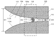
図13Aと図13Bは、実施の形態2におけるセンサデバイス100の上面断面図である。図13Aと図13Bにおいて、実施の形態1におけるセンサデバイス1と同じ部分には同じ参照番号を付す。実施の形態2におけるセンサデバイス100の側断面図は実施の形態1における図1Bに示すセンサデバイス1と同じである。図14Aと図14Bはそれぞれセンサデバイス100の側断面図および上面断面図である。センサデバイス100には、金属層102の下面102Bと、金属層103の上面103Aと、側壁部111の側面111Aと、側壁部112の側面112Aの4つの面により囲まれた流路104が形成されている。金属層102の下面102Bは流路104の上面を構成し、金属層103の上面103Aは流路104の下面を構成する。側壁部111の側面111Aは流路104の第1の側面を構成し、側壁部112の側面112Aは流路104の第2の側面を構成する。また、流路104は試料62が投入される投入領域115と試料62が排出される排出領域116を有する。投入領域115から排出領域116に向けて流路104の幅すなわち側面111Aと側面112Aとの間隔が徐々に小さくなるように流路104は形成されている。流路104の投入領域115の最前端(図面の左端)の幅W1、排出領域116の最後端(図面の右端)の幅W3、流路104内に位置する任意の場所104aの幅W2の関係は、W1≧W2≧W3となるように流路104が形成されている。流路104に試料62が投入されると試料62中のアナライト8と担体10のアクセプタ7が特異的に結合して凝集体11を形成する。投入領域115から排出領域116に向けて試料62が流れるに従って、凝集体11は排出領域116に向かって移動する。ここで、排出領域116の幅W4は、担体10の径よりも大きく、凝集体11の径より小さい。すなわち、排出領域116の幅W4は、担体10の径以上の第1の所定値よりも大きく、凝集体11の径より小さい第2の所定値以下である。
(Embodiment 2)
13A and 13B are top sectional views of the sensor device 100 according to the second embodiment. 13A and 13B, the same reference numerals are given to the same portions as those of the sensor device 1 in the first embodiment. A side sectional view of sensor device 100 in the second embodiment is the same as sensor device 1 shown in FIG. 1B in the first embodiment. 14A and 14B are a side sectional view and a top sectional view of the sensor device 100, respectively. The sensor device 100 is formed with a flow path 104 surrounded by four surfaces: a lower surface 102B of the metal layer 102, an upper surface 103A of the metal layer 103, a side surface 111A of the side wall 111, and a side surface 112A of the side wall 112. ing. The lower surface 102B of the metal layer 102 constitutes the upper surface of the channel 104, and the upper surface 103A of the metal layer 103 constitutes the lower surface of the channel 104. The side surface 111 </ b> A of the side wall portion 111 constitutes a first side surface of the channel 104, and the side surface 112 </ b> A of the side wall portion 112 constitutes a second side surface of the channel 104. Further, the flow path 104 has a loading area 115 into which the sample 62 is loaded and a discharging area 116 into which the sample 62 is discharged. The flow path 104 is formed so that the width of the flow path 104, that is, the distance between the side surface 111A and the side surface 112A gradually decreases from the input area 115 to the discharge area 116. Relationship between the width W1 of the foremost end (left end of the drawing) of the input region 115 of the flow path 104, the width W3 of the rearmost end (right end of the drawing) of the discharge area 116, and the width W2 of an arbitrary location 104a located in the flow path 104 The flow path 104 is formed so that W1 ≧ W2 ≧ W3. When the sample 62 is introduced into the flow path 104, the analyte 8 in the sample 62 and the acceptor 7 of the carrier 10 are specifically bound to form an aggregate 11. As the sample 62 flows from the input region 115 toward the discharge region 116, the aggregate 11 moves toward the discharge region 116. Here, the width W4 of the discharge region 116 is larger than the diameter of the carrier 10 and smaller than the diameter of the aggregate 11. That is, the width W <b> 4 of the discharge region 116 is greater than the first predetermined value that is greater than or equal to the diameter of the carrier 10 and less than or equal to the second predetermined value that is smaller than the diameter of the aggregate 11.

流路104においては、凝集体11が流路104の投入領域115と排出領域116との間の特定の領域118にトラップされる。このように、領域118は凝集体11をトラップする凝集体トラップ部である。凝集体11が領域118にトラップされると流路104を遮断する。次に流れてくる凝集体11は既にトラップされた凝集体11で止められ、凝集体11が特定の領域118に固まって留まる。すなわち、試料62中に存在し、第1の所定値以下の径を有する担体10と、担体10よりも小さい径を有する非特異的検体9と、媒質61とは領域118を通過できる。しかし、試料62中に存在し、第2の所定値より大きな径を有する凝集体11は領域118を通過できない。   In the flow path 104, the aggregate 11 is trapped in a specific area 118 between the input area 115 and the discharge area 116 of the flow path 104. Thus, the region 118 is an aggregate trap portion that traps the aggregate 11. When the aggregate 11 is trapped in the region 118, the flow path 104 is blocked. The next flowing aggregate 11 is stopped by the already trapped aggregate 11, and the aggregate 11 remains solidified in a specific region 118. That is, the carrier 10 present in the sample 62 and having a diameter equal to or smaller than the first predetermined value, the nonspecific specimen 9 having a smaller diameter than the carrier 10, and the medium 61 can pass through the region 118. However, the aggregate 11 present in the sample 62 and having a diameter larger than the second predetermined value cannot pass through the region 118.

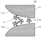
図15は凝集体11の概念図である。凝集体11はアナライトを介して互いに結合した2つ以上の担体10であり、種々の形状を取り得る。実施の形態においては、凝集体11の径とは、図15に示すように、凝集体11の最大径Rを指す。つまり、第2の所定値は最大径Rより小さい値である。 FIG. 15 is a conceptual diagram of the aggregate 11. Aggregates 11 are two or more carriers 10 bonded together via an analyte and can take various shapes. In the embodiment, the diameter of the aggregate 11 indicates the maximum diameter R of the aggregate 11 as shown in FIG. That is, the second predetermined value is a value smaller than the maximum diameter R.

このように、実施の形態2におけるセンサデバイス100では、流路104の特定の領域118にアナライト8を含む凝集体11をトラップすることができので、領域118における誘電率が他の領域と比べて大きく変化する。これにより、流路104の領域118に接する金属層102の領域から上方へ伝搬していく電磁波の状態(例えば可視光の色)と、流路104の領域118以外に接する金属層102の領域から上方へ伝搬していく電磁波の状態(例えば可視光の色)とが変化するので、家庭においてもユーザが容易にアナライトの存在を視覚的に確認できる。つまり、凝集体11をトラップせずに流路104中に均一に凝集体11が分布しているセンサデバイスと比較して実施の形態2におけるセンサデバイス100はより高い検出感度を有する。   As described above, in the sensor device 100 according to the second embodiment, the aggregate 11 including the analyte 8 can be trapped in the specific region 118 of the flow path 104. Therefore, the dielectric constant in the region 118 is higher than that in other regions. Change greatly. As a result, the state of the electromagnetic wave propagating upward from the region of the metal layer 102 in contact with the region 118 of the channel 104 (for example, the color of visible light) and the region of the metal layer 102 in contact with other than the region 118 of the channel 104 Since the state of the electromagnetic wave propagating upward (for example, the color of visible light) changes, the user can easily visually confirm the presence of the analyte even at home. That is, the sensor device 100 according to the second embodiment has higher detection sensitivity than the sensor device in which the aggregate 11 is uniformly distributed in the flow path 104 without trapping the aggregate 11.

凝集体11を流路104の特定の領域でトラップするためには、流路104において投入領域115から排出領域116に向かう方向へ試料62の流れを作る必要がある。図13Bに示すセンサデバイス100は、流路104の排出領域116の近傍に配置された吸収材113をさらに備える。吸収材113は試料62を吸収する。吸収材113により試料62が吸収されることにより流路104の投入領域115から排出領域116の方向へ試料62の流れを作ることができる。これにより、凝集体11および担体10は排出領域116へ向けて流れて行き、凝集体11は領域118でトラップされ、担体10は排出領域116から流路104の外側へ排出される。なお、図13Bに示す吸収材113は、図13Aに示すセンサデバイス100に追加されている。吸収材113は、図13Aに示すセンサデバイス100以外のセンサデバイスにおいても活用でき、図13Bに示すセンサデバイス100と同様に、流路4、104内の試料の流れを大きくできる。   In order to trap the aggregate 11 in a specific area of the flow path 104, it is necessary to create a flow of the sample 62 in the direction from the input area 115 to the discharge area 116 in the flow path 104. The sensor device 100 illustrated in FIG. 13B further includes an absorbent material 113 disposed in the vicinity of the discharge region 116 of the flow path 104. The absorbent material 113 absorbs the sample 62. When the sample 62 is absorbed by the absorbent material 113, the flow of the sample 62 can be made in the direction from the input region 115 to the discharge region 116 of the flow path 104. As a result, the aggregate 11 and the carrier 10 flow toward the discharge region 116, the aggregate 11 is trapped in the region 118, and the carrier 10 is discharged from the discharge region 116 to the outside of the flow path 104. Note that the absorbent material 113 shown in FIG. 13B is added to the sensor device 100 shown in FIG. 13A. The absorbent material 113 can also be used in sensor devices other than the sensor device 100 shown in FIG. 13A, and the flow of the sample in the flow paths 4 and 104 can be increased as in the sensor device 100 shown in FIG. 13B.

図13Aに示すセンサデバイス100では、流路104の幅W2は投入領域115の最前端から排出領域116の最後端まで連続的に減少する。流路104の幅W2は、投入領域115の最前端と排出領域116の最後端との間で不連続に減少してもよい。また、領域118の幅は連続的に減少するが、投入領域115および排出領域116の少なくとも一方の幅が一定値であってよい。   In the sensor device 100 shown in FIG. 13A, the width W2 of the flow path 104 continuously decreases from the foremost end of the input region 115 to the last end of the discharge region 116. The width W <b> 2 of the flow path 104 may decrease discontinuously between the foremost end of the input region 115 and the rearmost end of the discharge region 116. Further, although the width of the region 118 continuously decreases, the width of at least one of the input region 115 and the discharge region 116 may be a constant value.

(実施の形態3)
図16Aと図16Bは、それぞれ実施の形態3におけるセンサデバイス200の側断面図と拡大側断面図である。センサデバイス200の上面図は図1Aに示す実施の形態1におけるセンサデバイス1のそれと同じである。図16Aに示すように、センサデバイス200には、実施の形態1における側壁部21、22と同様の2つの側壁部の2つの側面と、金属層202の下面202Bと、金属層203の上面203Aとの4つの面により囲まれた流路204が形成されている。側壁部の2つの側面は流路204の第1と第2の側面を構成する。金属層202の下面202Bは流路204の上面を構成する。金属層203の上面203Aは流路204の下面を構成する。流路204は試料62が投入される投入領域215と試料62が排出される排出領域216と、それらの間に設けられた領域218を有する。領域218は凝集体11をトラップする凝集体トラップ部である。流路204は投入領域215および領域218(凝集体トラップ部)からなる流路204b(第1の流路)と、排出領域216からなる流路204c(第2の流路)により構成されている。そして、下面202Bと上面203Aとの間隔である流路204の深さのうち、流路204bの深さと流路204cの深さとの関係、すなわち流路204bでの金属層202の下面202Bと金属層203の上面203Aとの間隔D1と流路204cでの金属層202の下面202Bと金属層203の上面203Aとの間隔D2とはD1>D2となるように流路204が形成されている。流路204に試料62が投入されると試料62中のアナライト8と担体10のアクセプタ7が特異的に結合して凝集体11を形成する。投入領域215から排出領域216に向けて試料62が流れるに従って、凝集体11は排出領域216に向かって移動する。
(Embodiment 3)
16A and 16B are a side sectional view and an enlarged side sectional view, respectively, of the sensor device 200 according to the third embodiment. The top view of sensor device 200 is the same as that of sensor device 1 in the first embodiment shown in FIG. 1A. As shown in FIG. 16A, the sensor device 200 includes two side surfaces of two side wall portions similar to the side wall portions 21 and 22 in the first embodiment, a lower surface 202B of the metal layer 202, and an upper surface 203A of the metal layer 203. The flow path 204 surrounded by the four surfaces is formed. Two side surfaces of the side wall portion constitute first and second side surfaces of the flow path 204. The lower surface 202B of the metal layer 202 constitutes the upper surface of the flow path 204. The upper surface 203 </ b> A of the metal layer 203 constitutes the lower surface of the flow path 204. The flow path 204 includes an input region 215 into which the sample 62 is input, a discharge region 216 from which the sample 62 is discharged, and a region 218 provided therebetween. A region 218 is an aggregate trap portion that traps the aggregate 11. The flow path 204 includes a flow path 204b (first flow path) made up of the input area 215 and the area 218 (aggregate trap part) and a flow path 204c (second flow path) made up of the discharge area 216. . Of the depth of the channel 204 that is the distance between the lower surface 202B and the upper surface 203A, the relationship between the depth of the channel 204b and the depth of the channel 204c, that is, the lower surface 202B of the metal layer 202 and the metal in the channel 204b. The flow path 204 is formed so that the distance D1 between the upper surface 203A of the layer 203 and the distance D2 between the lower surface 202B of the metal layer 202 and the upper surface 203A of the metal layer 203 in the flow path 204c is D1> D2. When the sample 62 is introduced into the flow path 204, the analyte 8 in the sample 62 and the acceptor 7 of the carrier 10 are specifically bound to form an aggregate 11. As the sample 62 flows from the input region 215 toward the discharge region 216, the aggregate 11 moves toward the discharge region 216.

ここで、流路204cの深さ(間隔D2)は、担体10の径よりも大きく、凝集体11の径より小さく設定される。すなわち、流路204cの深さ(間隔D2)は、担体10の径以上の第1の所定値よりも大きく、凝集体11の径より小さい第2の所定値以下に設定される。   Here, the depth (interval D2) of the flow path 204c is set larger than the diameter of the carrier 10 and smaller than the diameter of the aggregate 11. That is, the depth (interval D2) of the flow path 204c is set to be equal to or smaller than a first predetermined value that is not less than the diameter of the carrier 10 and smaller than the diameter of the aggregate 11.

流路204においては、凝集体11が流路204の特定の領域218にトラップされる。すると、次に流れてくる凝集体11もこのトラップされた凝集体11により流路が遮断され、凝集体11が特定の領域218に固まって留まることになる。図16Bは、凝集体11がトラップされた領域218の拡大図である。すなわち、試料62中に存在し、その径が第1の所定値以下の担体10、担体10よりも小さい径を有する非特異的検体9と媒質61は領域218を通過できるが、第2の所定値より大きな径を有する凝集体11は領域218を通過できない。   In the flow path 204, the aggregate 11 is trapped in a specific region 218 of the flow path 204. Then, the flow of the aggregate 11 that flows next is blocked by the trapped aggregate 11, and the aggregate 11 is solidified and stays in the specific region 218. FIG. 16B is an enlarged view of the region 218 where the aggregates 11 are trapped. That is, the carrier 10 whose diameter is equal to or smaller than the first predetermined value and the non-specific specimen 9 and the medium 61 having a diameter smaller than that of the carrier 10 can pass through the region 218, but the second predetermined Aggregates 11 having a diameter larger than the value cannot pass through region 218.

このように、実施の形態3におけるセンサデバイス200では、流路204の特定の領域218にアナライト8を含む凝集体11をトラップすることができので、領域218における誘電率が他の領域と比べて大きく変化する。これにより、流路204の領域218に接する金属層202の領域から上方へ伝搬していく電磁波の状態(例えば可視光の色)と、流路204の領域218以外に接する金属層202の領域から上方へ伝搬していく電磁波の状態(例えば可視光の色)とが変化するので、家庭においてもユーザが容易にアナライトの存在を視覚的に確認できる。つまり、センサデバイス200は、凝集体11をトラップせずに流路中に均一に凝集体11が分布しているセンサデバイスと比較してアナライトの検出感度が高くなる。   Thus, in the sensor device 200 according to the third embodiment, the aggregate 11 including the analyte 8 can be trapped in the specific region 218 of the flow path 204, so that the dielectric constant in the region 218 is higher than that in other regions. Change greatly. Thus, from the state of the electromagnetic wave propagating upward from the region of the metal layer 202 in contact with the region 218 of the channel 204 (for example, the color of visible light) and the region of the metal layer 202 in contact with other than the region 218 of the channel 204 Since the state of the electromagnetic wave propagating upward (for example, the color of visible light) changes, the user can easily visually confirm the presence of the analyte even at home. That is, the sensor device 200 has higher analyte detection sensitivity than a sensor device in which the aggregate 11 is uniformly distributed in the flow path without trapping the aggregate 11.

また、実施の形態3におけるセンサデバイス200においても実施の形態2と同様に流路204内の試料62に流れを作るように排出領域216の近傍に吸収材を配置してもよい。その結果、流路204の投入領域215から排出領域216の方向へ試料62の流れができる。これにより、凝集体11および担体10は排出領域216へ向けて流れて行き、凝集体11は領域218でトラップされ、担体10は排出領域216から流路204の外側へ排出される。   Also in the sensor device 200 according to the third embodiment, an absorbent material may be disposed in the vicinity of the discharge region 216 so as to create a flow in the sample 62 in the flow path 204 as in the second embodiment. As a result, the sample 62 can flow from the input region 215 to the discharge region 216 of the flow path 204. As a result, the aggregate 11 and the carrier 10 flow toward the discharge region 216, the aggregate 11 is trapped in the region 218, and the carrier 10 is discharged from the discharge region 216 to the outside of the flow path 204.

図17は実施の形態3におけるセンサデバイス200における電界強度の分布を表わす。センサデバイス200において、図17に示すように、金属層202の流路204bに接する領域から上方へ伝搬していく電磁波の干渉状態と、金属層202の流路204cに接する領域から上方へ伝搬していく電磁波の干渉状態とを概ね同一状態としておいても良い。具体的には、流路204bと流路204cの設計を共に式1を満たすように行う、または、共に式2を満たすように行う。但し、式1や式2における整数mの値は、流路204bと流路204cで異なる。すなわち、流路204bの上面と下面との間隔D1および流路204cの上面と下面との間隔D2は、整数m1、m2と、電磁波の真空中での波長λと、流路204内の屈折率nと電磁波の入射角θとで表される以下の角θとで表される以下の関係(a)(b)、
(a)(m1+1/2)×λ=2×n×D1×cosθ、かつ、(m2+1/2)×λ=2×n×D2×cosθ、
(b)m1×λ=2×n×D1×cosθ、かつ、m2×λ=2×n×D2×cosθ
のうちの一方を満たす。
FIG. 17 shows the electric field intensity distribution in the sensor device 200 according to the third embodiment. In the sensor device 200, as shown in FIG. 17, the interference state of electromagnetic waves propagating upward from the region in contact with the flow path 204b of the metal layer 202 and the upward propagation from the region in contact with the flow path 204c of the metal layer 202 are performed. The interference state of the electromagnetic wave that travels may be set to be approximately the same. Specifically, both the flow path 204b and the flow path 204c are designed so as to satisfy the expression 1, or both are satisfied so as to satisfy the expression 2. However, the value of the integer m in Expression 1 and Expression 2 is different between the flow path 204b and the flow path 204c. That is, the distance D1 between the upper surface and the lower surface of the flow path 204b and the distance D2 between the upper surface and the lower surface of the flow path 204c are integers m1 and m2, the wavelength λ of the electromagnetic wave in vacuum, and the refractive index in the flow path 204. The following relationships (a) and (b) represented by the following angle θ represented by n and the incident angle θ of the electromagnetic wave,
(A) (m1 + 1/2) × λ = 2 × n × D1 × cos θ, and (m2 + 1/2) × λ = 2 × n × D2 × cos θ,
(B) m1 × λ = 2 × n × D1 × cos θ and m2 × λ = 2 × n × D2 × cos θ
Satisfy one of them.

これにより、例えば可視光帯の光をセンサデバイス200の金属層202の上方から供給した場合、金属層202の流路204bに接する領域と、金属層202の流路204cに接する領域からの反射光の色が概ね同一色となる。したがって、アナライト8と担体10のアクセプタ7が特異的に結合して凝集体11が形成されて凝集体トラップ部218(領域218)でトラップされ、凝集体トラップ部218に多数の凝集体11が留置されると、金属層202の凝集体トラップ部218に接する領域からの反射光の色が変化している事が明白に判る。これにより、家庭においてユーザが容易にアナライトの存在を視覚的に確認できるセンサデバイス200を実現できる。   Thereby, for example, when light in the visible light band is supplied from above the metal layer 202 of the sensor device 200, the reflected light from the region in contact with the flow path 204b of the metal layer 202 and the region in contact with the flow path 204c of the metal layer 202 Are almost the same color. Therefore, the analyte 8 and the acceptor 7 of the carrier 10 are specifically bound to form an aggregate 11 and trapped by the aggregate trap part 218 (region 218), and a large number of aggregates 11 are collected in the aggregate trap part 218. It can be clearly seen that the color of the reflected light from the region in contact with the aggregate trap portion 218 of the metal layer 202 changes when it is placed. Accordingly, it is possible to realize the sensor device 200 that allows the user to easily visually check the presence of the analyte at home.

センサデバイス200では、ユーザが色の変化を検知することで、アナライトの存在を検出するために、光源としては可視光帯の光源が使われるのが好ましい。ここで、可視光帯とは人間の目で見える光の波長帯であり、380nm以上750nm以下の波長の範囲である。ここで、例えば、アナライト8を含まない試料62を流路204に投入した状態で可視光帯であるオレンジ色〜赤色の580〜600nmの波長で式2の条件を満たすようにセンサデバイス200を設計する。そして、流路204にアナライト8を含む試料を投入し、凝集体トラップ部218(領域218)において屈折率(誘電率)が変化した結果、金属層202の凝集体トラップ部218に接する領域からの反射光の波長が560nm以下において式2を満たすように、担体の構成物質を選択したり、凝集体トラップ部218の構造を決定したりしても良い。これにより、特異的結合の有無により、人の目において色差の大きな黄色を示す波長(560〜580nm付近)を挟んで反射光の波長が変化するので、ユーザが家庭等において容易に特異的結合の有無を視覚的に確認する事ができる。   In the sensor device 200, it is preferable that a light source in the visible light band is used as the light source in order for the user to detect the presence of the analyte by detecting a color change. Here, the visible light band is a wavelength band of light that can be seen by human eyes, and is a range of wavelengths from 380 nm to 750 nm. Here, for example, the sensor device 200 is set so that the condition of Formula 2 is satisfied at a wavelength of 580 to 600 nm of orange to red that is a visible light band in a state where the sample 62 not including the analyte 8 is put into the flow path 204. design. Then, the sample containing the analyte 8 is introduced into the flow path 204, and the refractive index (dielectric constant) changes in the aggregate trap portion 218 (region 218). As a result, from the region in contact with the aggregate trap portion 218 of the metal layer 202 The constituent material of the carrier may be selected or the structure of the aggregate trap part 218 may be determined so that the formula 2 is satisfied when the wavelength of the reflected light is 560 nm or less. As a result, the wavelength of the reflected light changes across the wavelength (near 560 to 580 nm) showing a yellow color with a large color difference in the human eye depending on the presence or absence of specific binding, so that the user can easily perform specific binding at home or the like. The presence or absence can be confirmed visually.

また、センサデバイス200の上方とそれを観察するユーザの目との間に、特定波長のみ通すフィルターを配置しても良い。上記の例では、例えば、580nmより短波長の光を通さないフィルターを配置すると、試料62がアナライトを含まない場合は、580nm以上の光は通すので明るく見えるが、試料62がアナライトを含む場合は、式2の条件を満たす波長がフィルターにより減衰されるため、暗く見える。色差よりも明暗差の方が知覚しやすい場合があり、このような構成が有効の場合もある。   Further, a filter that allows only a specific wavelength to pass may be disposed between the upper side of the sensor device 200 and the eyes of the user who observes the sensor device 200. In the above example, for example, when a filter that does not pass light having a wavelength shorter than 580 nm is arranged, when the sample 62 does not contain an analyte, light of 580 nm or more passes through, so it looks bright, but the sample 62 contains an analyte. In this case, since the wavelength satisfying the condition of Expression 2 is attenuated by the filter, it looks dark. In some cases, light and dark differences are easier to perceive than color differences, and such a configuration may be effective.

(実施の形態4)
図18Aは実施の形態4におけるセンサデバイス300の上面断面図である。図18Bは図18Aに示すセンサデバイス300の線18B−18Bにおける側断面図である。図18Aと図18Bにおいて、図2Aと図2Bに示す実施の形態1におけるセンサデバイス1と同じ部分には同じ参照番号を付す。センサデバイス300には、側壁部311の側面311Aと、側壁部312の側面312Aと、金属層2の下面2Bと、金属層3の上面3Aの4つの面により囲まれた流路304が形成されている。側壁部311の側面311Aは流路304の第1の側面を構成する、側壁部312の側面312Aは流路304の第2の側面を構成する。金属層2の下面2Bは流路304の上面を構成する。別の金属層3の上面3Aは流路304の下面を構成する。センサデバイス300は、金属層2の下面2Bから金属層3の上面3Aまで側面311A、312Aと平行に延びる複数のピラー313を有する。複数のピラー313は流路304の特定の領域318に設けられており、実施の形態4では円柱状である。複数のピラー313は、円柱状以外の形状であってもよい。互いに隣りあう2本のピラー313の間隙p1と、側壁部311とピラー313の間隙p2と、側壁部312とピラー313の間隙p3は、複数のピラー313と側壁部311、312間の隙間を担体10は通過するが、凝集体11はトラップされるような寸法に設定されている。間隙p1は、互いに隣りあう2本のピラー313の側周面間の距離である。間隙p2は、側壁部311の側面311Aとピラー313の側周面との距離である。間隙p3は、側壁部312の側面312Aとピラー313の側周面との距離である。間隙p1、p2、p3は、担体10の径より大きく、凝集体11の径より小さく設定されている。すなわち、間隙p1、p2、p3は、担体10の径以上の第1の所定値より大きく、凝集体11の径より小さい第2の所定値以下に設定されている。このように、流路304の領域318は凝集体11をトラップする凝集体トラップ部として機能する。なお、複数本のピラー313は、流路304での試料の流れる方向と直角に交差するが、流路304での試料の流れる方向に傾斜して交差するように、側壁部311、312と所定の角度を持って傾斜して延びていてもよい。
(Embodiment 4)
FIG. 18A is a top sectional view of sensor device 300 according to the fourth exemplary embodiment. 18B is a cross-sectional side view taken along line 18B-18B of sensor device 300 shown in FIG. 18A. 18A and 18B, the same reference numerals are given to the same portions as those of the sensor device 1 in the first embodiment shown in FIGS. 2A and 2B. In the sensor device 300, a flow path 304 surrounded by four surfaces, that is, a side surface 311A of the side wall 311, a side surface 312A of the side wall 312, a lower surface 2B of the metal layer 2, and an upper surface 3A of the metal layer 3 is formed. ing. A side surface 311A of the side wall portion 311 constitutes a first side surface of the channel 304, and a side surface 312A of the side wall portion 312 constitutes a second side surface of the channel 304. The lower surface 2B of the metal layer 2 constitutes the upper surface of the flow path 304. The upper surface 3 </ b> A of another metal layer 3 constitutes the lower surface of the channel 304. The sensor device 300 has a plurality of pillars 313 extending from the lower surface 2B of the metal layer 2 to the upper surface 3A of the metal layer 3 in parallel with the side surfaces 311A and 312A. The plurality of pillars 313 are provided in a specific region 318 of the flow path 304, and in the fourth embodiment, have a cylindrical shape. The plurality of pillars 313 may have a shape other than a cylindrical shape. The gap p1 between the two adjacent pillars 313, the gap p2 between the side wall 311 and the pillar 313, and the gap p3 between the side wall 312 and the pillar 313 serve as a carrier between the plurality of pillars 313 and the side walls 311 and 312. 10 passes through, but the aggregate 11 is set to a size such that it is trapped. The gap p1 is the distance between the side peripheral surfaces of the two pillars 313 adjacent to each other. The gap p <b> 2 is a distance between the side surface 311 </ b> A of the side wall portion 311 and the side peripheral surface of the pillar 313. The gap p3 is a distance between the side surface 312A of the side wall portion 312 and the side peripheral surface of the pillar 313. The gaps p1, p2, and p3 are set larger than the diameter of the carrier 10 and smaller than the diameter of the aggregate 11. That is, the gaps p1, p2, and p3 are set to be larger than the first predetermined value that is equal to or larger than the diameter of the carrier 10 and smaller than the second predetermined value that is smaller than the diameter of the aggregate 11. As described above, the region 318 of the flow path 304 functions as an aggregate trap portion that traps the aggregate 11. The plurality of pillars 313 intersect with the side walls 311 and 312 in a predetermined manner so as to intersect with the sample flowing direction in the channel 304 at right angles, but incline and intersect with the sample flowing direction in the channel 304. It may be inclined and extended at an angle of.

図18Cは実施の形態4における他のセンサデバイス300Aの上面断面図である。図18Dは図18Cに示すセンサデバイス300Aの線18D−18Dにおける側断面図である。図18Cと図18Dにおいて、図18Aと図18Bに示すセンサデバイス300と同じ部分には同じ参照番号を付す。センサデバイス300Aは、図18Aと図18Bに示すセンサデバイス300の複数のピラー313の代りに金属層2の下面2Bから金属層3の上面3Aまで側面311A、312Aと平行に延びる複数のピラー313a、313bを有する。複数のピラー313a、313bは流路304の特定の領域318に設けられており、実施の形態4では円柱状である。複数のピラー313a、313bは、円柱状以外の形状であってもよい。ピラー313a、313bがお互いに千鳥状に2列に配列されている。この場合も、互いに隣りあうピラー313a、313bの間隙と、ピラー313aと側面311Aとの間隔と、ピラー313aと側面312Aとの間隙は、ピラー313a、313bと側壁部311、312間の隙間を担体10は通過するが、凝集体11はトラップされるような寸法に設定されている。また、複数のピラー313a、313bは3列以上配列されていてもよい。   FIG. 18C is a top cross-sectional view of another sensor device 300A according to Embodiment 4. 18D is a cross-sectional side view taken along line 18D-18D of sensor device 300A shown in FIG. 18C. 18C and 18D, the same reference numerals are given to the same portions as those of the sensor device 300 shown in FIGS. 18A and 18B. The sensor device 300A includes a plurality of pillars 313a extending in parallel with the side surfaces 311A and 312A from the lower surface 2B of the metal layer 2 to the upper surface 3A of the metal layer 3, instead of the plurality of pillars 313 of the sensor device 300 shown in FIGS. 18A and 18B. 313b. The plurality of pillars 313a and 313b are provided in a specific region 318 of the flow path 304, and in the fourth embodiment, have a cylindrical shape. The plurality of pillars 313a and 313b may have a shape other than a columnar shape. Pillars 313a and 313b are arranged in two rows in a staggered manner. In this case as well, the gap between the pillars 313a and 313b adjacent to each other, the gap between the pillar 313a and the side surface 311A, and the gap between the pillar 313a and the side surface 312A, the gap between the pillars 313a and 313b and the side wall portions 311 and 312 is supported. 10 passes through, but the aggregate 11 is set to a size such that it is trapped. The plurality of pillars 313a and 313b may be arranged in three or more rows.

複数本のピラー313が流路304は金属層2、3の面2B、3Bとではなく側面311A、312Aと接続されて、金属層2、3の面2B、3Bと平行に延びていてもよい。この場合も、互いに隣りあう2本のピラー313の間隙、ピラー313と金属層3の上面3Aとの間隔と、ピラー313と金属層2の下面2Bの間隙は、ピラー313と金属層2、3の間隙を担体10は通過するが、凝集体11はトラップされるような寸法に設定されている。   The plurality of pillars 313 may be connected to the side surfaces 311A and 312A instead of the surfaces 2B and 3B of the metal layers 2 and 3 so that the flow path 304 extends in parallel with the surfaces 2B and 3B of the metal layers 2 and 3. . Also in this case, the gap between the two pillars 313 adjacent to each other, the gap between the pillar 313 and the upper surface 3A of the metal layer 3, and the gap between the pillar 313 and the lower surface 2B of the metal layer 2 are the same. The carrier 10 passes through this gap, but the agglomerates 11 are set to dimensions that are trapped.

このように、実施の形態4におけるセンサデバイス300、300Aでは、流路304の特定の領域318にアナライト8を含む凝集体11をトラップすることができるので、領域318における誘電率が他の領域と比べて大きく変化する。これにより、流路304の領域318に接する金属層2の領域から上方へ伝搬していく電磁波の状態(例えば可視光の色)と、流路304の領域318以外に接する金属層2の領域から上方へ伝搬していく電磁波の状態(例えば可視光の色)とが変化するので、家庭においてもユーザが容易にアナライトの存在を確認できる。つまり、センサデバイス300、300Aは、凝集体11をトラップせずに流路中に均一に凝集体11が分布しているセンサデバイスと比較してアナライトの検出感度が高くなる。   As described above, in sensor devices 300 and 300A according to the fourth embodiment, aggregate 11 including analyte 8 can be trapped in specific region 318 of flow path 304, so that the dielectric constant in region 318 is other region. It changes greatly compared to. Thereby, from the state of the electromagnetic wave propagating upward from the region of the metal layer 2 in contact with the region 318 of the flow channel 304 (for example, the color of visible light) and the region of the metal layer 2 in contact with other than the region 318 of the flow channel 304 Since the state of the electromagnetic wave propagating upward (for example, the color of visible light) changes, the user can easily confirm the presence of the analyte even at home. That is, the sensor devices 300 and 300A have higher analyte detection sensitivity than a sensor device in which the aggregate 11 is uniformly distributed in the flow path without trapping the aggregate 11.

なお、図18Aから図18Dにおいて、互いに隣りあうピラー313、313a、313bの間隙は互いに異なっていてもよい。   18A to 18D, the gaps between the pillars 313, 313a, and 313b adjacent to each other may be different from each other.

(実施の形態5)
図19Aは実施の形態5におけるセンサデバイス400の上面断面図である。図19Bは図19Aに示すセンサデバイス400の線19B−19Bにおける側断面図である。図19Aと図19Bにおいて、図2Aと図2Bに示す実施の形態1におけるセンサデバイス1と同じ部分には同じ参照番号を付す。図19Aと図19Bに示すセンサデバイス400には、側壁部411の側面411Aと、側壁部412の側面412Aと、金属層2の下面2Bと、金属層3の上面3Aの4つの面により囲まれた流路404が形成されている。側壁部411の側面411Aは流路404の第1の側面を構成する。側壁部412の側面412Aは流路404の第2の側面を構成する。金属層2の下面2Bは流路404の上面を構成する。金属層3の上面3Aは流路404の下面を構成する。センサデバイス400は、流路404の特定の領域418に設けられた複数の繊維状物質413を有する。複数の繊維状物質413は互いに絡みあって空隙が形成された網目構造を有する。網目構造の空隙の最小径は、その空隙を担体10は通過するが、凝集体11は通過できないような寸法で設定されている。空隙の最小径は、担体10の径より大きく、凝集体11の径より小さい。すなわち、空隙の最小径は、担体10の径以上の第1の所定値より大きく、凝集体11の径より小さい第2の所定値以下の寸法で形成されている。流路404の特定の領域418には、複数の繊維状物質413が絡みあって空隙が形成された網目構造が設けられている。
(Embodiment 5)
FIG. 19A is a top sectional view of sensor device 400 in accordance with the fifth exemplary embodiment. FIG. 19B is a side cross-sectional view of sensor device 400 shown in FIG. 19A taken along line 19B-19B. 19A and 19B, the same reference numerals are given to the same portions as those of the sensor device 1 in the first embodiment shown in FIGS. 2A and 2B. The sensor device 400 shown in FIGS. 19A and 19B is surrounded by four surfaces: a side surface 411A of the side wall portion 411, a side surface 412A of the side wall portion 412, a lower surface 2B of the metal layer 2, and an upper surface 3A of the metal layer 3. A flow path 404 is formed. A side surface 411 </ b> A of the side wall part 411 constitutes a first side surface of the flow path 404. The side surface 412A of the side wall portion 412 constitutes the second side surface of the flow path 404. The lower surface 2B of the metal layer 2 constitutes the upper surface of the flow path 404. The upper surface 3A of the metal layer 3 constitutes the lower surface of the flow path 404. The sensor device 400 includes a plurality of fibrous substances 413 provided in a specific region 418 of the flow path 404. The plurality of fibrous materials 413 have a network structure in which voids are formed by being entangled with each other. The minimum diameter of the voids in the network structure is set such that the carrier 10 can pass through the voids but the aggregate 11 cannot pass through. The minimum diameter of the void is larger than the diameter of the carrier 10 and smaller than the diameter of the aggregate 11. That is, the minimum diameter of the gap is formed with a dimension that is larger than the first predetermined value that is equal to or larger than the diameter of the carrier 10 and smaller than the second predetermined value that is smaller than the diameter of the aggregate 11. A specific region 418 of the flow path 404 is provided with a network structure in which a plurality of fibrous substances 413 are entangled to form a void.

これにより、試料62に含まれる物質のうち、その径が繊維状物質413間の空隙の最小径よりも大きい物質である凝集体11がろ過物として繊維状物質413によりトラップされる。一方、試料62に含まれる物質のうち、その径が繊維状物質413間の空隙の最小径よりも小さい物質である担体10は繊維状物質413間を通過していく。このように、流路404の領域418は凝集体11をトラップする凝集体トラップ部として機能する。なお、この網目構造を有する繊維状物質413は、二酸化シリコンのナノファイバで構成されていてもよい。   Thereby, the aggregate 11 which is a substance whose diameter is larger than the minimum diameter of the gap between the fibrous substances 413 among the substances contained in the sample 62 is trapped by the fibrous substance 413 as a filtrate. On the other hand, among the substances contained in the sample 62, the carrier 10, which is a substance whose diameter is smaller than the minimum diameter of the gap between the fibrous substances 413, passes between the fibrous substances 413. As described above, the region 418 of the flow path 404 functions as an aggregate trap portion that traps the aggregate 11. The fibrous substance 413 having the network structure may be composed of silicon dioxide nanofibers.

このように、実施の形態5におけるセンサデバイス400では、流路404の特定の領域418にアナライト8を含む凝集体11をトラップすることができので、領域418における誘電率が他の領域と比べて大きく変化する。これにより、流路404の領域418に接する金属層2の領域から上方へ伝搬していく電磁波の状態(例えば可視光の色)と、流路404の領域418以外に接する金属層2の領域から上方へ伝搬していく電磁波の状態(例えば可視光の色)とが変化するので、家庭においてもユーザが容易にアナライトの存在を確認できる。つまり、センサデバイス400は、凝集体11をトラップせずに流路中に均一に凝集体11が分布しているセンサデバイスと比較してアナライトの検出感度が高くなる。   As described above, in the sensor device 400 according to the fifth embodiment, the aggregate 11 including the analyte 8 can be trapped in the specific region 418 of the flow path 404. Therefore, the dielectric constant in the region 418 is higher than that in other regions. Change greatly. Thus, from the state of the electromagnetic wave propagating upward from the region of the metal layer 2 in contact with the region 418 of the flow path 404 (for example, the color of visible light) and the region of the metal layer 2 in contact with other than the region 418 of the flow path 404 Since the state of the electromagnetic wave propagating upward (for example, the color of visible light) changes, the user can easily confirm the presence of the analyte even at home. That is, the sensor device 400 has higher analyte detection sensitivity than a sensor device in which the aggregate 11 is uniformly distributed in the flow path without trapping the aggregate 11.

(実施の形態6)
図20Aは実施の形態6におけるセンサデバイス500の上面断面図である。図20Bは図20Aに示すセンサデバイス500の線20B−20Bにおける側断面図である。図20Aと図20Bにおいて、図2Aと図2Bに示す実施の形態1におけるセンサデバイス1と同じ部分には同じ参照番号を付す。図20Aと図20Bに示すセンサデバイス500には、側壁部511の側面511Aと、側壁部512の側面512Aと、金属層2の下面2Bと、金属層3の上面3Aの4つの面により囲まれた流路504が形成されている。側壁部511の側面511Aは流路504の第1の側面を構成する。側壁部512の側面512Aは流路504の第2の側面を構成する。金属層2の下面2Bは流路504の上面を構成する。金属層3の上面3Aは流路504の下面を構成する。流路504の側面511A、512Aは、特定の領域518a、518bにおいて凹んでいる凹部511P、512Pを有するように蛇行している。試料62が、流路504を流れている間に領域518a、518bに形成された凹部511P、512Pに凝集体11がトラップされる。流路504の特定の領域518a、518bは凝集体11をトラップする凝集体トラップ部として機能する。なお、側面511Aと側面512Aのどちらか一方の側面のみが凹部を有するように蛇行していてもよい。
(Embodiment 6)
FIG. 20A is a top cross-sectional view of sensor device 500 according to Embodiment 6. 20B is a cross-sectional side view taken along line 20B-20B of sensor device 500 shown in FIG. 20A. 20A and 20B, the same reference numerals are given to the same portions as those of the sensor device 1 in the first embodiment shown in FIGS. 2A and 2B. 20A and 20B, the sensor device 500 is surrounded by four surfaces: a side surface 511A of the side wall portion 511, a side surface 512A of the side wall portion 512, a lower surface 2B of the metal layer 2, and an upper surface 3A of the metal layer 3. A flow path 504 is formed. A side surface 511 </ b> A of the side wall portion 511 constitutes a first side surface of the flow path 504. A side surface 512 </ b> A of the side wall portion 512 constitutes a second side surface of the flow path 504. The lower surface 2B of the metal layer 2 constitutes the upper surface of the channel 504. The upper surface 3A of the metal layer 3 constitutes the lower surface of the flow path 504. The side surfaces 511A and 512A of the flow path 504 meander so as to have recesses 511P and 512P that are recessed in specific regions 518a and 518b. While the sample 62 flows through the flow path 504, the aggregate 11 is trapped in the recesses 511P and 512P formed in the regions 518a and 518b. The specific regions 518a and 518b of the flow path 504 function as an aggregate trap portion that traps the aggregate 11. It should be noted that only one of the side surface 511A and the side surface 512A may meander so as to have a recess.

このように、実施の形態6におけるセンサデバイス500では、流路504の特定の領域518にアナライト8を含む凝集体11をトラップすることができるので、領域518における誘電率が他の領域と比べて大きく変化する。これにより、流路504の領域518a、518bに接する金属層2の領域から上方へ伝搬していく電磁波の状態(例えば可視光の色)と、流路504の領域518a、518b以外に接する金属層2の領域から上方へ伝搬していく電磁波の状態(例えば可視光の色)とが変化するので、家庭においてもユーザが容易にアナライトの存在を確認できる。つまり、センサデバイス500は、凝集体11をトラップせずに流路中に均一に凝集体11が分布しているセンサデバイスと比較してアナライトの検出感度が高くなる。   As described above, in sensor device 500 in the sixth embodiment, aggregate 11 including analyte 8 can be trapped in specific region 518 of flow path 504, so that the dielectric constant in region 518 is higher than that in other regions. Change greatly. Accordingly, the state of electromagnetic waves propagating upward from the region of the metal layer 2 in contact with the regions 518a and 518b of the flow path 504 (for example, the color of visible light) and the metal layer in contact with other than the regions 518a and 518b of the flow path 504 Since the state of electromagnetic waves propagating upward from the region 2 (for example, the color of visible light) changes, the user can easily confirm the presence of the analyte even at home. That is, the sensor device 500 has higher analyte detection sensitivity than a sensor device in which the aggregate 11 is uniformly distributed in the flow path without trapping the aggregate 11.

(実施の形態7)
図21Aと図21Bはそれぞれ実施の形態7におけるセンサデバイス700の断面図と下面斜視図である。実施の形態7におけるセンサデバイス700は、ATR(Attenuated Total Reflection)型のセンサデバイスである。
(Embodiment 7)
21A and 21B are a sectional view and a bottom perspective view, respectively, of the sensor device 700 according to the seventh embodiment. The sensor device 700 according to the seventh embodiment is an ATR (Attenuated Total Reflection) type sensor device.

センサデバイス700は、プリズム701と、プリズム701の下面に配置された絶縁層703と、絶縁層703の下面に設けられた金属層702とを有する。絶縁層703は所定の誘電率を有し、平坦な下面を有する。   The sensor device 700 includes a prism 701, an insulating layer 703 disposed on the lower surface of the prism 701, and a metal layer 702 provided on the lower surface of the insulating layer 703. The insulating layer 703 has a predetermined dielectric constant and has a flat lower surface.

センサデバイス700の絶縁層703はガラスなどの透明な絶縁体で構成されている。絶縁層703の下面には溝形状の流路704が形成されている。流路704は側面703Cと、側面703Dと、金属層702の下面702Bの3つの面から構成されている。金属層702は絶縁層703の下面703Bの少なくとも一部の領域に設けられている。側面703Cは流路704の第1の側面を構成する。側面703Dは流路704の第2の側面を構成する。金属層702の下面702Bは流路704の上面を構成する。   The insulating layer 703 of the sensor device 700 is made of a transparent insulator such as glass. A groove-shaped channel 704 is formed on the lower surface of the insulating layer 703. The flow path 704 includes three surfaces: a side surface 703C, a side surface 703D, and a lower surface 702B of the metal layer 702. The metal layer 702 is provided in at least a part of the lower surface 703 </ b> B of the insulating layer 703. The side surface 703C constitutes the first side surface of the flow path 704. The side surface 703D constitutes the second side surface of the flow path 704. The lower surface 702B of the metal layer 702 constitutes the upper surface of the channel 704.

流路704は、試料を投入する投入領域715と、試料を排出する排出領域716と、投入領域715と排出領域716との間に設けられた特定の領域718を有している。領域718には投入された試料が流れ、試料中のアナライトを含んだ凝集体をトラップする凝集体トラップ部として機能する。流路704内には、その表面にアナライトが特異的結合し凝集体を生成する複数のアクセプタを固定した担体が物理的に吸着されている。図21Aに示すセンサデバイス700は、使用時には上下を逆転して使用される。   The flow path 704 has an input region 715 for supplying a sample, a discharge region 716 for discharging a sample, and a specific region 718 provided between the input region 715 and the discharge region 716. The input sample flows into the region 718, and functions as an aggregate trap part that traps aggregates containing the analyte in the sample. In the channel 704, a carrier on which a plurality of acceptors that specifically bind an analyte to form an aggregate is fixed is physically adsorbed on the surface. The sensor device 700 shown in FIG. 21A is used by turning it upside down during use.

投入領域715から投入された試料は、投入時にユーザがスポイドなどにより試料を押し出すことにより、投入領域715から排出領域716へ向けて流れる。流路704に配置された担体に試料中のアナライトが特異的結合し、凝集体を形成して領域718においてトラップされる。領域718は、実施の形態1、2、4、5、6におけるセンサデバイスの特定の領域18、118、218、318、418、518a、518bのいずれかと同様に構成可能である。   The sample introduced from the input region 715 flows from the input region 715 toward the discharge region 716 when the user pushes out the sample with a spoid or the like at the time of input. The analyte in the sample specifically binds to the carrier arranged in the channel 704 and forms an aggregate and is trapped in the region 718. The region 718 can be configured in the same manner as any of the specific regions 18, 118, 218, 318, 418, 518a, and 518b of the sensor device in the first, second, fourth, fifth, and sixth embodiments.

金属層702と絶縁層703との界面には、電子の疎密波である表面プラズモン波が存在している。プリズム701側の上方には光源705が配置され、光源705からプリズム701へP偏光された光を全反射条件で入射する。このとき、金属層702と絶縁層703との表面にはエバネセント波が生じている。金属層702において全反射された光は、検波部706において受光され、光の強度が検出される。   At the interface between the metal layer 702 and the insulating layer 703, a surface plasmon wave that is an electron density wave exists. A light source 705 is disposed above the prism 701 side, and P-polarized light is incident on the prism 701 from the light source 705 under total reflection conditions. At this time, evanescent waves are generated on the surfaces of the metal layer 702 and the insulating layer 703. The light totally reflected by the metal layer 702 is received by the detection unit 706, and the intensity of the light is detected.

ここで、エバネセント波と表面プラズモン波との波数が一致する波数整合条件が満たされると、光源705から供給される光のエネルギーは表面プラズモン波の励起に利用され、反射光の強度が減少する。波数整合条件は、光源705から供給される光の入射角に依存する。したがって、入射角を変化させて検波部706で反射光強度を検出すると、ある入射角において、反射光の強度が減少する。   Here, when the wave number matching condition in which the wave numbers of the evanescent wave and the surface plasmon wave match is satisfied, the energy of the light supplied from the light source 705 is used for excitation of the surface plasmon wave, and the intensity of the reflected light decreases. The wave number matching condition depends on the incident angle of light supplied from the light source 705. Accordingly, when the reflected light intensity is detected by the detector 706 while changing the incident angle, the intensity of the reflected light decreases at a certain incident angle.

反射光の強度が最小となる角度である共鳴角は、絶縁層703の誘電率に依存している。試料中の被測定物質であるアナライトとアクセプタとが特異的に結合して生成された特異的結合物が絶縁層703の上面に構成されると、絶縁層703の誘電率が変化し、これに応じて、共鳴角が変化する。したがって、共鳴角の変化をモニタリングすることにより、アナライトとアクセプタとの特異的結合反応の結合の強さや結合の速さなどを検知することが可能となる。   The resonance angle that is the angle at which the intensity of the reflected light is minimized depends on the dielectric constant of the insulating layer 703. When a specific binding substance generated by specifically binding an analyte which is a substance to be measured in the sample and an acceptor is formed on the upper surface of the insulating layer 703, the dielectric constant of the insulating layer 703 changes. Accordingly, the resonance angle changes. Therefore, by monitoring the change in the resonance angle, it is possible to detect the strength of binding and the speed of binding in the specific binding reaction between the analyte and the acceptor.

実施の形態7におけるセンサデバイス700では、流路704の特定の領域718にアナライトを含む凝集体をトラップすることができるので、領域718における誘電率が他の領域と比べて大きく変化する。これにより、センサデバイス700は、凝集体をトラップせずに流路中に均一に凝集体が分布している図22に示す従来のセンサデバイス600等のセンサデバイスと比較してアナライトの検出感度が高くなる。   In the sensor device 700 according to Embodiment 7, since the aggregate including the analyte can be trapped in the specific region 718 of the flow path 704, the dielectric constant in the region 718 changes greatly compared to other regions. As a result, the sensor device 700 has an analyte detection sensitivity compared to a sensor device such as the conventional sensor device 600 shown in FIG. 22 in which the aggregate is uniformly distributed in the flow path without trapping the aggregate. Becomes higher.

以上説明したように、本発明のセンサデバイスは、流路内の特定の領域にアクセプタを含んだ凝集体をトラップすることにより、アクセプタをその領域に偏在させることができる。従って、流路内の特定領域における誘電率が他の領域と比べて大きく変化し、試料中のアクセプタを感度よく検出することが可能となる。   As described above, the sensor device of the present invention traps the aggregate containing the acceptor in a specific region in the flow path, whereby the acceptor can be unevenly distributed in that region. Therefore, the dielectric constant in a specific region in the flow path changes greatly compared to other regions, and it becomes possible to detect the acceptor in the sample with high sensitivity.

なお、実施の形態1〜7において、金属層とは面状の層のみを指しておらず、細かい金属粒子が一面に敷き詰められた状態をも指している。   In the first to seventh embodiments, the metal layer does not refer to only a planar layer, but also refers to a state in which fine metal particles are spread all over.

また、図2A、図4A、図4B、図8A、図8B、図9、図11等に示すセンサデバイスでは、担体やアクセプタは金属層2の下面2Bだけに配置したが、これに限る必要はなく、金属層3の上面3Aにだけ配置しても、金属層2、3の面2B、3Aの両方に配置しても同様の効果が得られる。   Further, in the sensor device shown in FIGS. 2A, 4A, 4B, 8A, 8B, 9, 11 and the like, the carrier and the acceptor are arranged only on the lower surface 2B of the metal layer 2, but this is not necessary. However, the same effect can be obtained by arranging only on the upper surface 3A of the metal layer 3 or arranging both on the surfaces 2B and 3A of the metal layers 2 and 3.

以上の実施の形態において、「上面」「下面」「上方」「下方」等の方向を示す用語は、流路や金属層等のセンサデバイスの構成部品の相対的な位置関係にのみ依存する相対的な方向を示し、鉛直方向等の絶対的な方向を示すものではない。   In the above embodiments, the terms indicating directions such as “upper surface”, “lower surface”, “upper”, and “lower” are relative only depending on the relative positional relationship of the components of the sensor device such as the flow path and the metal layer. It does not indicate an absolute direction such as a vertical direction.

本発明におけるセンサデバイスは、検出感度が高く、小型で簡易な構造を有するので、小型で低コストのバイオセンサ等に利用する事ができる。   Since the sensor device in the present invention has high detection sensitivity and a small and simple structure, it can be used for a small and low-cost biosensor or the like.

1,100,200,300,400,500,600,700 センサデバイス
2,3,102,103,202,203,602,702 金属層
4,104,204,304,404,504,704 流路
7,7a,7b,604 アクセプタ
8 アナライト
9 非特異的検体
10,10a,10b 担体
11 凝集体
15,115,215,715 投入領域
16,116,216,716 排出領域
18,118,218,318,418,518a,518b,718 領域(凝集体トラップ部)
21,22,111,112,311,312,411,412,511,512 側壁部
23 フィルター
24 注入口
25,26 貯留部
31a,31b 超音波発生源
32 ヒータ(加熱源)
33a,33b 磁界発生源
61 媒質
62 試料
91,93 電磁波
92 電磁波源
204b 流路(第1の流路)
204c 流路(第2の流路)
313,313a,313b ピラー
1, 100, 200, 300, 400, 500, 600, 700 Sensor device 2, 3, 102, 103, 202, 203, 602, 702 Metal layer 4, 104, 204, 304, 404, 504, 704 Channel 7 , 7a, 7b, 604 Acceptor 8 Analyte 9 Non-specific specimen 10, 10a, 10b Carrier 11 Aggregate 15, 115, 215, 715 Input region 16, 116, 216, 716 Discharge region 18, 118, 218, 318, 418, 518a, 518b, 718 region (aggregate trap part)
21, 22, 111, 112, 311, 312, 411, 412, 511, 512 Side wall part 23 Filter 24 Injection port 25, 26 Storage part 31 a, 31 b Ultrasonic wave generation source 32 Heater (heating source)
33a, 33b Magnetic field generation source 61 Medium 62 Sample 91, 93 Electromagnetic wave 92 Electromagnetic wave source 204b Flow path (first flow path)
204c channel (second channel)
313, 313a, 313b Pillar

Claims (17)

試料中のアナライトを検出するように構成されたセンサデバイスであって、
上方より電磁波が入射されるように構成された上面と、下面と、第1の側面と、前記第1の側面に対向する第2の側面とに囲まれて、前記試料が流れるように構成されて、担体が配置されるように構成された流路と、
前記流路の前記上面および前記下面の少なくとも一方の少なくとも一部に設けられた金属層と、
を備え、
前記担体の表面には前記アナライトと特異的結合して凝集体を生成する複数のアクセプタが固定されるように構成されており、
前記流路は、前記アナライトが偏在するように構成された凝集体トラップ部を有し、
前記流路は、
前記試料が投入されて前記凝集体トラップ部を流れるように構成された投入領域と、
前記凝集体トラップ部を流れた前記試料が排出されるように構成された排出領域と、
前記凝集体トラップ部から前記投入領域側に設けられた第1の流路と、
前記凝集体トラップ部から前記排出領域側に設けられた第2の流路と、
をさらに有し、
前記凝集体の径は前記担体の径より大きく、
前記第1の流路における前記上面と前記下面の間隔は前記凝集体の前記径よりも大きく、前記第2の流路における前記上面と前記下面の間隔は前記担体の径よりも大きくかつ前記凝集体の前記径より小さい、センサデバイス。
A sensor device configured to detect an analyte in a sample, comprising:
Surrounded by an upper surface, a lower surface, a first side surface, and a second side surface opposite to the first side surface configured to receive electromagnetic waves from above, the sample flows. A flow path configured to dispose the carrier;
A metal layer provided on at least a part of at least one of the upper surface and the lower surface of the flow path;
With
A plurality of acceptors that specifically bind to the analyte and generate aggregates are fixed to the surface of the carrier,
The flow path may have a aggregates trap portion configured such that the analyte is unevenly distributed,
The flow path is
An input region configured to allow the sample to be input and to flow through the aggregate trap portion;
A discharge region configured to discharge the sample flowing through the aggregate trap part;
A first flow path provided on the side of the charging region from the aggregate trap part;
A second flow path provided on the discharge region side from the aggregate trap part;
Further comprising
The diameter of the aggregate is larger than the diameter of the carrier,
The distance between the upper surface and the lower surface in the first flow path is larger than the diameter of the aggregate, and the distance between the upper surface and the lower surface in the second flow path is larger than the diameter of the carrier and A sensor device smaller than the diameter of the aggregate .
試料中のアナライトを検出するように構成されたセンサデバイスであって、
上方より電磁波が入射されるように構成された上面と、第1の側面と、前記第1の側面に対向する第2の側面とに囲まれて、前記試料が流れるように構成されて、担体が配置されるように構成された流路と、
前記流路の前記上面の少なくとも一部領域に設けられた金属層と、
を備え、
前記担体の表面には前記アナライトと特異的結合し凝集体を生成する複数のアクセプタが固定されるように構成されており、
前記流路は、前記アナライトが偏在するように構成された凝集体トラップ部を有し、
前記流路は、
前記試料が投入されて前記凝集体トラップ部を流れるように構成された投入領域と、
前記凝集体トラップ部を流れた前記試料が排出されるように構成された排出領域と、
前記凝集体トラップ部から前記投入領域側に設けられた第1の流路と、
前記凝集体トラップ部から前記排出領域側に設けられた第2の流路と、
をさらに有し、
前記凝集体の径は前記担体の径より大きく、
前記第1の流路における前記上面と前記下面の間隔は前記凝集体の前記径よりも大きく、前記第2の流路における前記上面と前記下面の間隔は前記担体の径よりも大きくかつ前記凝集体の前記径より小さい、センサデバイス。
A sensor device configured to detect an analyte in a sample, comprising:
Surrounded by an upper surface configured to receive electromagnetic waves from above, a first side surface, and a second side surface opposite to the first side surface, the sample is configured to flow, and the carrier A flow path configured to be disposed;
A metal layer provided in at least a partial region of the upper surface of the flow path;
With
A plurality of acceptors that specifically bind to the analyte and generate aggregates are immobilized on the surface of the carrier,
The flow path may have a aggregates trap portion configured such that the analyte is unevenly distributed,
The flow path is
An input region configured to allow the sample to be input and to flow through the aggregate trap portion;
A discharge region configured to discharge the sample flowing through the aggregate trap part;
A first flow path provided on the side of the charging region from the aggregate trap part;
A second flow path provided on the discharge region side from the aggregate trap part;
Further comprising
The diameter of the aggregate is larger than the diameter of the carrier,
The distance between the upper surface and the lower surface in the first flow path is larger than the diameter of the aggregate, and the distance between the upper surface and the lower surface in the second flow path is larger than the diameter of the carrier and A sensor device smaller than the diameter of the aggregate .
前記担体は前記流路内に物理吸着固定されている、請求項1または2に記載のセンサデバイス。 The sensor device according to claim 1, wherein the carrier is fixed by physical adsorption in the flow path. 前記流路は前記凝集体トラップ部と異なる別の領域をさらに有し、
前記担体の前記流路の前記凝集体トラップ部での存在密度は、前記流路の前記別の領域での存在密度よりも高い、請求項1または2に記載のセンサデバイス。
The flow path further has another region different from the aggregate trap part,
3. The sensor device according to claim 1, wherein a density of the carrier in the aggregate trap portion of the flow path is higher than a density of presence in the another region of the flow path.
前記アクセプタは、前記流路内の前記凝集体トラップ部における前記金属層の表面に化学吸着固定されるように構成されている、請求項1または2に記載のセンサデバイス。 The sensor device according to claim 1, wherein the acceptor is configured to be chemisorbed and fixed to a surface of the metal layer in the aggregate trap portion in the flow path. 記凝集体トラップ部は、前記担体を通過させて前記凝集体は通過させない、請求項1または2に記載のセンサデバイス。 Before SL aggregates trap portion, said aggregates by passing the carrier does not pass, the sensor device according to claim 1 or 2. 記流路の前記第1の側面と前記第2の側面の間隔が前記投入領域から前記排出領域へ向けて小さくなり、
前記排出領域での前記第1の側面と前記第2の側面の間隔は前記担体の前記径より大きくかつ前記凝集体の前記径より小さい、請求項6に記載のセンサデバイス。
Before spacing of said first side and said second side of Kiryuro decreases toward from the charged area to the discharge area,
The sensor device according to claim 6, wherein a distance between the first side surface and the second side surface in the discharge region is larger than the diameter of the carrier and smaller than the diameter of the aggregate.
前記凝集体トラップ部は、前記流路内に配置された複数のピラーを有し、
前記複数のピラーのうちの互いに隣りあう2つのピラーの間隙は前記担体の前記径よりも大きくかつ前記凝集体の前記径より小さい、請求項6に記載のセンサデバイス。
The aggregate trap part has a plurality of pillars arranged in the flow path,
The sensor device according to claim 6, wherein a gap between two pillars adjacent to each other among the plurality of pillars is larger than the diameter of the carrier and smaller than the diameter of the aggregate.
前記凝集体トラップ部は、前記流路内に配置された網目構造を有し、
前記網目構造の空隙の最小径は前記担体の前記径より大きくかつ前記凝集体の前記径より小さい、請求項6に記載のセンサデバイス。
The aggregate trap portion has a network structure disposed in the flow path,
The sensor device according to claim 6, wherein a minimum diameter of the mesh structure void is larger than the diameter of the carrier and smaller than the diameter of the aggregate.
前記網目構造はSiO2ナノファイバの繊維状物質からなる、請求項9に記載のセンサデバイス。 The sensor device according to claim 9, wherein the network structure is made of a fibrous material of SiO 2 nanofibers. 前記第1の流路の前記上面と前記下面との間隔D1および前記第2の流路の前記上面と前記下面との間隔D2は、整数m1、m2と、電磁波の真空中での波長λと、前記流路内の屈折率nと前記電磁波の入射角θとで表される以下の関係(a)(b)、
(a)(m1+1/2)×λ=2×n×D1×cosθ、かつ、(m2+1/2)×λ=2×n×D2×cosθ、
(b)m1×λ=2×n×D1×cosθ、かつ、m2×λ=2×n×D2×cosθ、のうちの一方を満たす、請求項に記載のセンサデバイス。
The distance D1 between the upper surface and the lower surface of the first flow path and the distance D2 between the upper surface and the lower surface of the second flow path are integers m1 and m2, and the wavelength λ of electromagnetic waves in vacuum. The following relationships (a) and (b) represented by the refractive index n in the flow path and the incident angle θ of the electromagnetic wave:
(A) (m1 + 1/2) × λ = 2 × n × D1 × cos θ, and (m2 + 1/2) × λ = 2 × n × D2 × cos θ,
The sensor device according to claim 1 , wherein (b) satisfies one of m1 × λ = 2 × n × D1 × cos θ and m2 × λ = 2 × n × D2 × cos θ.
前記流路の前記第1の側面及び前記第2の側面の少なくとも一方が凹部を有するように蛇
行して形成されており、
前記凝集体トラップ部が前記凹部である請求項1に記載のセンサデバイス。
At least one of the first side surface and the second side surface of the flow path is formed to meander so as to have a recess,
The sensor device according to claim 1, wherein the aggregate trap portion is the concave portion.
記排出領域の近傍に設けられて前記試料を吸収するように構成された吸収体をさらに備えた、請求項1に記載のセンサデバイス。 Before SL provided in the vicinity of the discharge region further comprising a constructed absorber to absorb the sample, the sensor device according to claim 1. 前記流路内に超音波を印加する超音波発生源をさらに備えた、請求項1または2に記載のセンサデバイス。 The sensor device according to claim 1, further comprising an ultrasonic wave generation source that applies an ultrasonic wave to the flow path. 前記流路内を加熱する加熱源をさらに備えた、請求項1または2に記載のセンサデバイス。 The sensor device according to claim 1, further comprising a heating source for heating the inside of the flow path. 前記担体は磁性体であり、
前記流路内に磁界が印加されるように構成されている、請求項1または2に記載のセンサデバイス。
The carrier is a magnetic material;
The sensor device according to claim 1 or 2, wherein a magnetic field is applied in the flow path.
前記電磁波は、可視光帯を含む光である、請求項1または2に記載のセンサデバイス。 The sensor device according to claim 1, wherein the electromagnetic wave is light including a visible light band.
JP2014503445A 2012-03-05 2013-02-20 Sensor device Active JP6019415B2 (en)

Applications Claiming Priority (3)

Application Number Priority Date Filing Date Title
JP2012047628 2012-03-05
PCT/JP2013/000924 WO2013132761A1 (en) 2012-03-05 2013-02-20 Sensor device

Publications (2)

Publication Number Publication Date
JPWO2013132761A1 JPWO2013132761A1 (en) 2015-07-30
JP6019415B2 true JP6019415B2 (en) 2016-11-02

Family

ID=49116257

Family Applications (1)

Application Number Title Priority Date Filing Date
JP2014503445A Active JP6019415B2 (en) 2012-03-05 2013-02-20 Sensor device

Country Status (4)

Country Link
US (1) US9829486B2 (en)
JP (1) JP6019415B2 (en)
CN (1) CN104272089B (en)
WO (1) WO2013132761A1 (en)

Families Citing this family (4)

* Cited by examiner, † Cited by third party
Publication number Priority date Publication date Assignee Title
FR3012131B1 (en) 2013-10-18 2018-01-19 Centre National De La Recherche Scientifique CONTRAST AMPLIFIER SUPPORTS FOR SAMPLE OBSERVATION, METHODS OF MAKING SAME, AND USES THEREOF
CN107504912B (en) * 2017-09-22 2020-04-17 京东方科技集团股份有限公司 Thickness testing method and device
JP7278826B2 (en) * 2019-03-26 2023-05-22 東芝テック株式会社 Detection sensor, measurement device, and sample preparation device
JP7229828B2 (en) * 2019-03-26 2023-02-28 東芝テック株式会社 detector

Family Cites Families (23)

* Cited by examiner, † Cited by third party
Publication number Priority date Publication date Assignee Title
US5515864A (en) * 1994-04-21 1996-05-14 Zuckerman; Ralph Method and apparatus for the in vivo measurement of oxygen concentration levels by the indirect determination of fluoescence lifetime
US6327410B1 (en) * 1997-03-14 2001-12-04 The Trustees Of Tufts College Target analyte sensors utilizing Microspheres
US6696022B1 (en) * 1999-08-13 2004-02-24 U.S. Genomics, Inc. Methods and apparatuses for stretching polymers
JP2003507026A (en) * 1999-08-13 2003-02-25 ユー.エス.ジェノミクス,インコーポレーテッド Method and apparatus for stretching a polymer
WO2001038873A2 (en) * 1999-11-24 2001-05-31 Biotronic Technologies, Inc. Devices and methods for detecting analytes using electrosensor having capture reagent
US7790443B2 (en) * 2002-08-27 2010-09-07 Vanderbilt University Bioreactors with substance injection capacity
WO2004020342A2 (en) * 2002-08-27 2004-03-11 Vanderbilt University Capillary perfused bioreactors with multiple chambers
JP4224641B2 (en) 2003-11-28 2009-02-18 国立大学法人東京工業大学 Localized surface plasmon sensor, sensing device, and sensing method
JP3978440B2 (en) * 2004-05-31 2007-09-19 財団法人川村理化学研究所 Silica / polymer / metal composite material and method for producing the same
US7670509B2 (en) * 2004-05-31 2010-03-02 Kawamura Institute Of Chemical Research Composite nanofiber, composite nanofiber association, complex structure, and production method thereof
US7298472B2 (en) * 2004-12-28 2007-11-20 Rheodyne, Llc Fluid analysis apparatus
JP4920674B2 (en) * 2005-03-18 2012-04-18 キヤノン株式会社 Structure, separation element, separation device, capture element, detection device, method for producing the same, and method for separating and detecting target substance
GB0508983D0 (en) * 2005-05-03 2005-06-08 Oxford Gene Tech Ip Ltd Cell analyser
US8510056B2 (en) * 2005-10-24 2013-08-13 Western Michigan University Research Foundation Method and integrated microsystem for detecting biomolecules in liquid
JP2009515162A (en) * 2005-11-07 2009-04-09 コーニンクレッカ フィリップス エレクトロニクス エヌ ヴィ Prop base biosensor and method for producing the same
US7998708B2 (en) * 2006-03-24 2011-08-16 Handylab, Inc. Microfluidic system for amplifying and detecting polynucleotides in parallel
US7359048B2 (en) * 2006-04-28 2008-04-15 Hewlett-Packard Development Company, L.P. Raman signal-enhancing structures and devices
JP5397577B2 (en) * 2007-03-05 2014-01-22 オムロン株式会社 Surface plasmon resonance sensor and chip for the sensor
KR100860701B1 (en) * 2007-03-14 2008-09-26 한양대학교 산학협력단 Long range surface plasmon optical waveguide sensors having double metal layers
JP5295149B2 (en) * 2010-02-25 2013-09-18 富士フイルム株式会社 Biological material analysis method and biological material analysis cell, chip and apparatus used therefor
WO2011136344A1 (en) 2010-04-28 2011-11-03 パナソニック電工株式会社 Chemical sensor
JPWO2011142118A1 (en) 2010-05-12 2013-07-22 パナソニック株式会社 Plasmon sensor and method of using and manufacturing the same
CN102884415B (en) * 2010-05-12 2015-10-07 松下知识产权经营株式会社 Phasmon sensor and using method thereof and manufacture method

Also Published As

Publication number Publication date
US20140370584A1 (en) 2014-12-18
CN104272089B (en) 2017-05-10
JPWO2013132761A1 (en) 2015-07-30
US9829486B2 (en) 2017-11-28
WO2013132761A1 (en) 2013-09-12
CN104272089A (en) 2015-01-07

Similar Documents

Publication Publication Date Title
JP6019415B2 (en) Sensor device
CN101583864A (en) Wiregrid waveguide
JP4533044B2 (en) Sensor
JP4548416B2 (en) Localized plasmon resonance sensor and inspection device
CN103649724A (en) SPR sensor device with nanostructure
CN101203743A (en) Luminescence sensors using sub-wavelength apertures or slits
JP4463610B2 (en) Surface plasmon resonance sensor device
JP5308390B2 (en) Test substance detection method and test substance detection apparatus
JP5810267B2 (en) Plasmon sensor, method of use and manufacturing method thereof
US9046484B2 (en) Plasmon sensor
JP2010540924A (en) Sensor device for detection of target components
CN109154566A (en) Biosensor and the method for analyzing sample using it
JP5315381B2 (en) Fluorescence detection apparatus, sample cell for fluorescence detection, and fluorescence detection method
CN102077072B (en) Fluid providing apparatus
US7106429B2 (en) Apparatus and method for detecting change of dielectric constant
JP2015114219A (en) Electric field enhancement element, analysis device, and electronic device
JP2012145516A (en) Measuring apparatus and sensor chip
WO2014106881A1 (en) Duct device
JP6205585B2 (en) Optical sensor
WO2012132313A1 (en) Immunoassay device
JP2011107069A (en) Surface plasmon resonance sensing system and surface plasmon resonance in-line measuring method
JP5602053B2 (en) Test substance detection method, test substance detection chip and test substance detection apparatus used therefor
Tarumaraja et al. Graphene-Based Plasmonic Photonic Crystal Waveguide Integrated Biosensor Circuit
JP2013167462A (en) Sensor
JP2014055841A (en) Microchip and analyzing device using microchip

Legal Events

Date Code Title Description
A621 Written request for application examination

Free format text: JAPANESE INTERMEDIATE CODE: A621

Effective date: 20151008

RD01 Notification of change of attorney

Free format text: JAPANESE INTERMEDIATE CODE: A7421

Effective date: 20160520

A131 Notification of reasons for refusal

Free format text: JAPANESE INTERMEDIATE CODE: A131

Effective date: 20160607

A521 Request for written amendment filed

Free format text: JAPANESE INTERMEDIATE CODE: A523

Effective date: 20160711

TRDD Decision of grant or rejection written
A01 Written decision to grant a patent or to grant a registration (utility model)

Free format text: JAPANESE INTERMEDIATE CODE: A01

Effective date: 20160823

A61 First payment of annual fees (during grant procedure)

Free format text: JAPANESE INTERMEDIATE CODE: A61

Effective date: 20160905

R151 Written notification of patent or utility model registration

Ref document number: 6019415

Country of ref document: JP

Free format text: JAPANESE INTERMEDIATE CODE: R151