JP5849714B2 - Remote-controlled drain plug device - Google Patents
Remote-controlled drain plug device Download PDFInfo
- Publication number
- JP5849714B2 JP5849714B2 JP2012006083A JP2012006083A JP5849714B2 JP 5849714 B2 JP5849714 B2 JP 5849714B2 JP 2012006083 A JP2012006083 A JP 2012006083A JP 2012006083 A JP2012006083 A JP 2012006083A JP 5849714 B2 JP5849714 B2 JP 5849714B2
- Authority
- JP
- Japan
- Prior art keywords
- operation button
- drain plug
- flange member
- connection pipe
- guide
- Prior art date
- Legal status (The legal status is an assumption and is not a legal conclusion. Google has not performed a legal analysis and makes no representation as to the accuracy of the status listed.)
- Active
Links
Images
Landscapes
- Sink And Installation For Waste Water (AREA)
Description
本発明は、浴槽や洗面ボウルなどの水槽の排水口を開閉するのに使用される遠隔操作式の排水栓装置に関する。 The present invention relates to a remote-operated drain plug device used to open and close a drain of a water tank such as a bathtub or a wash bowl.
特許文献1に示されているように、従来、遠隔操作式の排水栓装置では、その操作部を浴槽の縁に取り付ける際に、操作部の上下動をガイドする貫通孔を有するフランジ部材とフランジ部材の外周に螺合する締付具とで浴槽を挟持するように固定し、さらに、レリースワイヤが収められた接続管をフランジ部材の下端部にロック部材で締結していた。このロック部材は、弾性変形することにより胴体部にワンタッチで装着される。具体的には、ロック部材に形成されたアームを胴体部に装着する際に、二股に分岐して弾性変形可能なアームが胴体部によって押し広げられた後、弾性変形が復元してアームが胴体部に接触するようにして、ロック部材が胴体部に装着される。 As shown in Patent Document 1, conventionally, in a remote-operated drain plug device, a flange member and a flange having a through-hole for guiding the vertical movement of the operation portion when the operation portion is attached to the edge of the bathtub The bathtub is fixed with a fastener that is screwed onto the outer periphery of the member, and the connecting pipe containing the release wire is fastened to the lower end of the flange member with a lock member. The lock member is elastically deformed and attached to the body portion with one touch. Specifically, when the arm formed on the lock member is attached to the body portion, the arm that can be bifurcated and elastically deformed is spread by the body portion, and then the elastic deformation is restored to restore the arm to the body portion. The lock member is attached to the body part so as to contact the part.
しかし、接続管の締結は、浴槽の縁の下方で行われるためロック部材が装着されていることを確認しにくい。そのため接続管がしっかりと装着されず、接続管が外れてしまうことがあった。また、フランジ部材と接続管の間に嵌め込まれたOリングの摩擦力によって接続管が中途半端に固定されてしまい、ロック部材が装着されぬまま放置されてしまう恐れがあった。その場合、Oリングの摩擦力では、接続管の固定状態を維持できず、接続管がフランジ部材から外れてしまい、漏水する恐れがあった。
そこで、本発明は、接続管がフランジ部材に接続されていることを、容易に確認することが可能な遠隔操作式の排水栓装置を提供することを目的とする。
However, since the connection pipe is fastened below the edge of the bathtub, it is difficult to confirm that the lock member is attached. For this reason, the connecting pipe is not securely attached, and the connecting pipe may come off. Further, the connecting pipe is fixed halfway by the frictional force of the O-ring fitted between the flange member and the connecting pipe, and the lock member may be left without being attached. In that case, the connection state of the connecting pipe cannot be maintained by the frictional force of the O-ring, and the connecting pipe may come off from the flange member, causing water leakage.
Therefore, an object of the present invention is to provide a remote-operated drain plug device that can easily confirm that the connecting pipe is connected to the flange member.
請求項1の発明は、水槽に設けられた排水口を閉じる排水栓蓋を、操作ボタンの操作によってレリースワイヤを介して昇降させて前記排水口を開閉する遠隔操作式排水栓装置において、前記操作ボタンが取り付けられる取付対象部に形成された貫通孔に表面側から挿入され、内部に前記操作ボタンを進退可能とする案内面を有し、周囲に雄ネジが設けられた円筒部と、当該円筒部の上部に形成されたフランジと、を有するフランジ部材と、前記取付対象部の裏面側から前記円筒部の雄ネジに螺合される雌ネジが設けられて、前記フランジと共に前記取付対象部を挟持する締付ナットと、で構成された操作部ガイド部と、前記操作ボタンの進退動作を前記レリースワイヤに伝達する機構部を内部に保持するとともに、前記操作部ガイド部に下方から接続可能な接続管と、前記接続管を前記操作部ガイド部に接続させる接続管用接続具と、を備え、さらに、前記接続管と前記操作部ガイド部との接続が不良である場合に、前記操作ボタンの前記フランジ部材への組込み動作あるいは前記操作ボタンの前記フランジ部材の内部での進退動作のいずれかを規制して、前記操作ボタンによる前記排水栓蓋の開閉の切替えを不能とする規制手段を備えたことを特徴とする遠隔操作式排水栓装置である。 The invention according to claim 1 is a remote-operated drain plug device that opens and closes the drain port by raising and lowering a drain plug lid for closing a drain port provided in a water tank through a release wire by operating an operation button. A cylindrical portion that is inserted from the surface side into a through-hole formed in the attachment target portion to which the button is attached, has a guide surface that allows the operation button to move forward and backward, and has a male screw around it, and the cylinder A flange member formed on an upper portion of the portion, and a female screw that is screwed into a male screw of the cylindrical portion from the back side of the attachment target portion, and the attachment target portion together with the flange. An operation part guide part composed of a clamping nut for clamping, and a mechanism part for transmitting the forward / backward movement of the operation button to the release wire are held inside, and the operation part guide part is below the operation part guide part. A connecting pipe that can be connected, and a connecting pipe connector for connecting the connecting pipe to the operation part guide part, and further, when the connection between the connection pipe and the operation part guide part is poor, Restriction that disables switching of opening and closing of the drain plug lid by the operation button by restricting either the operation of incorporating the operation button into the flange member or the advancement / retraction operation of the operation button inside the flange member A remote-operated drain plug device comprising means.
これによれば、接続管用接続具による操作部ガイド部への接続管の接続が不十分となり、接続管の接続が不良となった場合には、規制手段によって、操作ボタンがフランジ部材への組込みができず操作ボタンの動きがレリースワイヤに伝達されない、あるいは、操作ボタンがフランジ部材内部で押し込めない。これにより、操作ボタンによる排水栓の昇降が不能となるので、接続管の接続不良を容易に確認することができる。 According to this, when the connection pipe connection to the operation section guide part by the connection pipe connector becomes insufficient and the connection pipe connection becomes poor, the operation button is incorporated into the flange member by the regulating means. The movement of the operation button cannot be transmitted to the release wire, or the operation button cannot be pushed inside the flange member. Thereby, since the raising / lowering of the drain plug by an operation button becomes impossible, the connection defect of a connecting pipe can be confirmed easily.
請求項2の発明は、請求項1において、前記規制手段は、前記フランジ部材の円筒部内を降下する前記操作ボタンが衝突して操作ボタンの降下を停止させるように、前記フランジ部材の円筒部内に設けられた凸部としたことを特徴とする遠隔操作式排水栓装置である。 According to a second aspect of the present invention, in the first aspect of the present invention, in the first aspect, the restricting means is disposed in the cylindrical portion of the flange member so that the operation button descending in the cylindrical portion of the flange member collides to stop the lowering of the operation button. A remote-operated drain plug device characterized in that it is provided with a convex portion.
これによれば、接続管が接続不良である場合には、降下中の操作ボタンが凸部に衝突して操作ボタンの進退動作が途中で停止する。そのため、操作ボタンを操作しても排水栓蓋が昇降しないので、接続管が接続不良になっていることを容易に確認することができる。 According to this, when the connection pipe is poorly connected, the operation button that is being lowered collides with the convex portion, and the operation button advances and retracts midway. Therefore, even if the operation button is operated, the drain plug lid does not move up and down, so that it can be easily confirmed that the connection pipe is poorly connected.
請求項3の発明は、請求項1において、前記規制手段は、前記フランジ部材の円筒部の少なくとも一部を内向きに変形させて前記操作ボタンの前記円筒部内への挿入を規制する弾性片であることを特徴とする遠隔操作式排水栓装置である。 According to a third aspect of the present invention, in the first aspect, the restricting means is an elastic piece that restricts the insertion of the operation button into the cylindrical portion by deforming at least a part of the cylindrical portion of the flange member inward. There is a remote-operated drain plug device.
これによれば、接続管が接続不良である場合には、操作ボタンをフランジ部に挿入する組込みの途中で操作ボタンの挿入が規制されて動かなくなる。そのため、操作ボタンはレリースワイヤの機能部に装着されない状態となり、操作ボタンを操作しても排水栓蓋が昇降しないので、接続管が接続不良になっていることを容易に確認することができる。 According to this, when the connection pipe is poorly connected, the insertion of the operation button is restricted during the incorporation of the operation button into the flange portion, and the operation button does not move. Therefore, the operation button is not attached to the function part of the release wire, and even if the operation button is operated, the drain plug lid does not move up and down, so that it can be easily confirmed that the connection pipe is poorly connected.
本発明によれば、接続管がフランジ部材に接続されていることを、容易に確認することが可能な排水栓装置が提供される。 ADVANTAGE OF THE INVENTION According to this invention, the drain plug apparatus which can confirm easily that a connecting pipe is connected to the flange member is provided.
以下、図面を参照して、本発明の実施の形態を説明する。
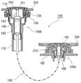
図1は本発明の第一の実施形態にかかる排水栓装置を示す概略図である。
排水栓装置100は、浴槽200(水槽)に設けられた排水口210に取り付けられる排水栓部100Aと、浴槽200のリム面220に形成された貫通孔221(図2参照)に取り付けられる操作部100Bと、を備え、排水栓部100Aと操作部100Bとをレリースワイヤ160で接続した遠隔操作式の排水栓装置である。レリースワイヤ160は、操作部100Bと排水栓部100Aとを接続するように設けられたホース170の内部に配設され、アウターチューブの内部でインナーワイヤが進退するように構成されている。
Embodiments of the present invention will be described below with reference to the drawings.
FIG. 1 is a schematic view showing a drain plug device according to a first embodiment of the present invention.
The
排水栓部100Aは、浴槽200の排水口210の下部に取り付けられた支持金具180にレリースワイヤ160の一端に設けられた作動部165を保持させ、その作動部165に排水口210を閉じる排水栓蓋190を取り付けている。後述する操作ボタン150の操作によってレリースワイヤ160を介して作動部165が排水栓蓋190を昇降させることにより、排水口210を開閉する。なお、図示しないが、支持金具180には、前述したホース170の一端が取り付けられている。
The
次に、操作部100Bについて説明する。
図2は排水栓装置の操作部を示す側面図、図3は操作部の中央縦断面図、図4は操作部の分解図である。
操作部100Bは、外周面に雄ネジ113が形成された円筒部111の上端部に外向きのフランジ112を設けたフランジ部材110と、フランジ部材110の雄ネジ113に螺合する雌ネジ121を有する締付ナット120と、レリースワイヤ160の他端に設けられた機構部162を保持してフランジ部材110の円筒部111の下端に下方から接続される接続管130と、接続管130を締付ナット120に取り付ける接続管用接続具140と、フランジ部材110の円筒部111の内部に進退可能に配設された操作ボタン150と、を備えている。これらのフランジ部材110、締付ナット120、接続管130、接続管用接続具140、操作ボタン150は、いずれも樹脂製部材である。
Next, the
2 is a side view showing an operation part of the drain plug device, FIG. 3 is a central longitudinal sectional view of the operation part, and FIG. 4 is an exploded view of the operation part.
The
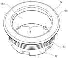
フランジ部材110は浴槽200のリム面220の表面側から貫通孔221に挿通される。締付ナット120は、浴槽200のリム面220の裏面側から、雌ネジ121をフランジ部材110の雄ネジ113に螺合させる。雌ネジ121を雄ネジ113に締め付けて、フランジ部材110のフランジ112と締付ナット120とで浴槽200のリム面220を挟持する。そして、フランジ部材110の円筒部111の内周が、操作ボタン150を進退可能に支える案内面114となる。これにより、フランジ部材110と締付ナット120とが、浴槽200のリム面220に設けた貫通孔221に対して操作ボタン150の進退をガイドする操作部ガイド部Aとなる。
また、案内面114の下部には、内方に突出する凸部115を設けている(図7参照)。本実施形態では、この凸部115を、90度間隔で4個設けている。
The
In addition, a
締付ナット120は、その外周面の下方に、後述するガイド溝122を複数設けている。また、締付ナット120の下部に、接続管130の上端部が挿入可能な凹部123を形成している。
The tightening
接続管130は、下端部にレリースワイヤ160の周囲を囲うホース170が接続され、上端部を操作部ガイド部Aに接続している。また、接続管130の内部に、機構部162を保持する保持部131を形成している。また、接続管130は、上端部を外向きに突出させた突出部132とし、その外周側面に、Oリング133を嵌める溝134を設けている。このOリング133は、接続管130が操作部ガイド部Aに接続されると、接続管130の上端部が締付ナット120の凹部123に挿入されて、締付ナット120の凹部123の内周面に密接してシールする。
The connecting
接続管接続具140は、接続管130の上部寄りの端部に回転可能に設けられている。具体的には、接続管130の上部の周囲に形成した浅溝部135に、接続管接続具140を部分的に係合させて、接続管接続具140を浅溝部135に沿って回転可能にしている。また、接続管接続具140を浅溝部135に係合させた状態で、接続管接続具140の水平上面が接続管130の突出部132の下面に接する。そして、接続管接続具140の内周部の上方に、後述する突起141を複数設けている。
The
接続管130を操作部ガイド部Aに接続する際には、接続管130の上端を操作部ガイド部Aに近づけた状態で操作部接続具140を回して、突起141を前述した締付ナット120のガイド溝122に挿入し、さらに操作部接続具140を回し続けて突起141をガイド溝122のロック位置122cまで到達させて、接続管130の接続は完了となる。
When connecting the connecting
操作ボタン150は、上面を円形の操作面151とし、操作面151の周囲から下方に垂下部152を延設し、垂下部152の上部に鍔部153を設けた形状である。操作ボタン150は、機構部162の内部から操作ボタン側に突き出たロッド163の先端に装着される。操作ボタン150を押すたびに、操作ボタン150を押す力がロッド163から機構部162に伝わり、レリースワイヤ160を介して排水栓蓋190を昇降する。
The
機構部162は、操作ボタン150を押すたびにロッド163が機構部162内に押込まれて、機構部162内でレリースワイヤ160のインナーワイヤを押し込んで、操作ボタン150の進退動作をレリースワイヤ160に伝えるように機能する。また、使用者が操作ボタン150から手を離すと、押込まれたロッド163を上昇させる復帰バネ(図示せず)を内蔵して、操作ボタン150を上昇させるように機能する。さらに、本実施形態では、機構部162の内部にラッチ機構(図示せず)を内蔵させ、押しボタン150を押すたびに、高い位置と低い位置とに交互に押しボタン150が位置するようにして、排水栓蓋190が排水口210を閉じる位置と排水口210を開く位置とに保持するようにしている。
Whenever the
次に、操作部ガイド部Aに接続管140を接続する構造について説明する。
図5は操作部を浴槽のリム部に取り付ける状態を示す側面図、図6は図5と同じ状態における操作部を示す中央縦断面図、図7はフランジ部材を示す側面図、図8はフランジ部材を浴槽のリム部に取り付ける締付ナットを示す側面図である。
Next, a structure for connecting the connecting
5 is a side view showing a state in which the operation unit is attached to the rim portion of the bathtub, FIG. 6 is a central longitudinal sectional view showing the operation unit in the same state as FIG. 5, FIG. 7 is a side view showing the flange member, and FIG. It is a side view which shows the clamping nut which attaches a member to the rim | limb part of a bathtub.
前述したように、接続管用接続具140は、その内周部の上方に突起141を設けている。本実施形態では、90度間隔で4個の突起141を設けている。
As described above, the
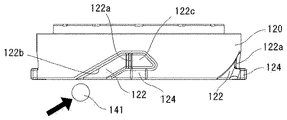
また、操作部ガイド部Aの一部を構成する締付ナット120は、その外周部に突起141を差し込み可能なガイド溝122を、突起141と同じく4個設けている。このガイド溝122は、締付ナット120の外周面を内方に凹ませて形成している。このガイド溝120の凹みは、突起141がガイド溝120から外れて空回りしないように適度な深さになっている。また、ガイド溝122の手前を締付ナット120の下面に開放して、その解放端から突起141を挿入するようにされている。
Further, the tightening
ガイド溝122の奥には、差し込まれた突起141を動かぬように拘束するロック部が設けられている。本実施形態においては、このロック部は、ガイド溝122の底面122eを部分的に浅くする段部122aで構成している。接続管接続具140をロックする際には、接続管接続具140を回して突起141の頂点が段部122aを乗り越えるように力をかけて接続管接続具140を回転させることによって、突起141をロック位置122cに到達させる。
また、ガイド溝122の解放端から段部122aの間に、ガイド溝122に受け入れた突起141を斜め上向きに案内する傾斜ガイド部122bを設けている。
さらに、ガイド溝122には、脱落防止部124を設けている。本実施形態では、この脱落防止部124は、段部122aより奥側、すなわちガイド溝122のロック位置122cの下部に、外側に突出させた突出壁を設けることにより、突起141がガイド溝122から外れないように構成している。これにより、接続管130が左右に傾くような方向に力が加わった場合でも、この突出壁が、突起141のガイド溝122へのかかり代を大きくするように働くので、接続管130が操作部ガイド部Aから外れるのを防止することができる。
A lock portion that restrains the inserted
Further, an
Further, a
接続管130を操作部ガイド部Aに接続する際には、まず、接続管130の上端を操作部ガイド部Aに近づけた状態で操作部接続具140を回して、突起141を前述した締付ナット120のガイド溝122に挿入する。次いで、操作部接続具140を回し続けて、突起141をガイド溝122の傾斜ガイド部122b内を移動させることによって接続管接続具140を上方に移動させて接続管130の上端部を締付ナット120の下面に設けた凹部123に徐々に挿入させる。この際、接続管130に取り付けたOリング133も接続管接続具140を回すことによって軽い力で凹部123に挿入される。そして、さらに操作部接続具140を回して、突起141をガイド溝122のロック位置122cまで到達させて、接続管130の接続は完了となる。
When connecting the
次に、本実施形態において、接続管の接続不良の際に操作ボタンの動作を規制する構成について説明する。
図9は接続管が正常に接続された排水栓装置において、操作ボタンを最も押し下げた状態を示す中央縦断面図である。
操作ボタン150を図9に示す位置まで押し下げると、機構部162内のラッチ機構が働いて、開栓状態と閉栓状態が切り替わる。なお、本実施形態上では、便宜上、操作ボタン150が上昇しているときは排水栓蓋190が下降して排水口210を閉じる閉栓状態とし、操作ボタン150が下降しているときは排水栓蓋190が上昇して排水口210を開く開栓状態としているが、この逆であってもよい。
Next, in the present embodiment, a configuration for restricting the operation of the operation button when the connection pipe is poorly connected will be described.
FIG. 9 is a central longitudinal sectional view showing a state in which the operation button is pushed down most in the drain plug device in which the connection pipe is normally connected.
When the
接続管130が正常に接続されていれば、押しボタン150の進退動作の軌跡上にフランジ部材110の凸部115が干渉することがない。そのため、閉栓状態の操作ボタン150を押し下げて図9の状態とし、操作ボタン150から手を離すと、前述した機構部162内の復帰バネおよびラッチ機構の働きにより操作ボタン150は少しだけ上昇した位置で静止して開栓状態となる。
If the connecting
これに対して、接続管130が正常に接続されていない状態では、押しボタン150の進退動作の軌跡上にフランジ部材110の凸部115が干渉して、押しボタン150の進退動作が規制される。
図10は接続管が正常に接続されていない排水栓装置において、操作ボタンを押し下げた状態を示す中央縦断面図である。
接続管接続具140がガイド溝122に対して不適切に締付けられると、締付ナット120の凹部123に接続管130の上端部が完全に挿入されず、接続管130は正常な位置よりも低い位置となる。すると、図10に示すように、接続管130に保持された機構部162やロッド163も低い位置となる。すると、操作ボタン150を押し下げて、操作ボタン150の鍔部153を、フランジ部材110の凸部115に接触する位置まで下降しても、機構部162のラッチ機構が閉栓状態から開栓状態に切り替わらず、手を離すと操作ボタン150は元の位置に戻ってしまい、一旦開いた排水栓蓋190も閉栓状態に戻る。このように、フランジ部材110の凸部115が、接続管130の操作部ガイド部Aへの接続が不良であった場合に操作ボタン150のフランジ部材110内での進退動作を規制して排水栓蓋190の開閉切替を不能とする規制手段として機能する。
On the other hand, in a state where the
FIG. 10 is a central longitudinal sectional view showing a state where the operation button is pushed down in the drain plug device in which the connection pipe is not normally connected.
When the
このように、本実施形態では、接続管130の接続不良があった場合には、操作ボタン150を押し下げる途中でフランジ部材110の凸部115によって操作ボタン150の進退動作が規制されるので、排水栓蓋190の開閉が切り替わることなく、また、操作ボタン150も元の位置に戻るから、操作ボタン150を押し下げたときの操作ボタンの動きや排水栓の開閉切替えの状態から接続管130が接続不良である可能性があることがわかる。そのため、排水栓装置の施工後に、操作ボタン150によって排水栓の開閉を試運転すれば、接続管の接続不良を速やかに発見することができ、施工ミスによる排水栓装置の動作不良を防止することができる。
Thus, in this embodiment, when there is a connection failure in the
また、接続管130を操作部ガイド部Aに確実に接続することが可能となるから、施工後に接続管130が外れることがない。よって、浴槽200のリム面220からフランジ部材110の円筒部111内面を通過した水を、接続管130やホース170を通して確実に排水管に排出することができるから、排水栓装置100の接続部から漏水する恐れもない。
Moreover, since it becomes possible to connect the
次に、本発明の第二の実施形態について説明する。
図11は本発明の第二の実施形態にかかる排水栓装置の操作部のフランジ部材を示す側面図、図12は排水栓装置の操作部の中央縦断面図、図13は操作部の分解図である。なお、前述した実施形態と同じ構成については、同じ符号を付してその説明を省いている。
Next, a second embodiment of the present invention will be described.
11 is a side view showing a flange member of the operation part of the drain plug device according to the second embodiment of the present invention, FIG. 12 is a central longitudinal sectional view of the operation part of the drain plug device, and FIG. 13 is an exploded view of the operation part. It is. In addition, about the same structure as embodiment mentioned above, the same code | symbol is attached | subjected and the description is abbreviate | omitted.
操作部300Bは、外周面に雄ネジ313が形成された円筒部311の上端部に外向きのフランジ312を設けたフランジ部材310と、フランジ部材310の雄ネジ313に螺合する雌ネジ321を有する締付ナット320と、レリースワイヤ160の他端に設けられた機構部162を保持してフランジ部材310の円筒部311の下端に下方から接続される接続管330と、接続管330を締付ナット320に取り付ける接続管用接続具340と、フランジ部材310の円筒部311の内部に進退可能に配設された操作ボタン150と、を備えている。これらのフランジ部材310、締付ナット320、接続管130、接続管用接続具340、操作ボタン150は、いずれも樹脂製部材である。
The
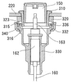
フランジ部材310は、浴槽200のリム面220の表面側から貫通孔221に挿通される。締付ナット320は、浴槽200のリム面220の裏面側から、雌ネジ321をフランジ部材310の雄ネジ313に螺合させる。雌ネジ321を雄ネジ313に締め付けて、フランジ部材310のフランジ312と締付ナット320とで浴槽200のリム面220を挟持する。そして、フランジ部材310の円筒部311の内周が、操作ボタン150を進退可能に支える案内面314となる。これにより、第一の実施形態と同様に、フランジ部材310と締付ナット320とが、浴槽200のリム面220に設けた貫通孔221に対して操作ボタン150の進退をガイドする操作部ガイド部A2となる。案内面314の下部には、円筒部311の下端部から二条のスリットを入れて、そのスリットの間を弾性片315としている。さらに、弾性片315の外側の下端部に、外向き凸部316を設けている。本実施形態では、この弾性片315を90度間隔で4個設けている。
The
締付ナット320は、その外周面に雄ネジ322を複数設けている。また、締付ナット320の下部に、接続管130の上端部が挿入可能な凹部323を形成している。
The tightening
接続管330は、下端部にレリースワイヤ160の周囲を囲うホース(図示せず)が接続され、上端部を操作部ガイド部Aに接続している。また、接続管330の内部に、機構部162を保持する保持部331を形成している。また、接続管330は、上端部を外向きに突出させた突出部332とし、その外周側面に、Oリング333を嵌める溝334を設けている。このOリング333は、接続管330が操作部ガイド部Aに接続されると、接続管330の上端部が締付ナット320の凹部123に挿入されて、締付ナット320の凹部323の内周面に密接してシールする。
The connecting
接続管接続具340は、接続管330の上部寄りの端部に回転可能に設けられている。具体的には、接続管330の上部の周囲に形成した浅溝部335に、接続管接続具340を部分的に係合させて、接続管接続具340を浅溝部335に沿って回転可能にしている。また、接続管接続具340を浅溝部335に係合させた状態で、接続管接続具340の水平上面が接続管330の突出部332の下面に接する。そして、接続管接続具340の内周部に、締付ナット320の雄ネジ322に螺合する雌ネジ342を設けている。
The
接続管330を操作部ガイド部Aに接続する際には、接続管330の上端を操作部ガイド部Aに近づけた状態で操作部接続具340を回して、雌ネジ342を雄ネジ322に螺合させ、接続管330の接続は完了となる。
When connecting the
次に、本実施形態において、接続管の接続不良の際に操作ボタンの動作を規制する構成について説明する。
図14は接続管が正常に接続されていない排水栓装置において、操作ボタンを装着しようとした状態を示す中央縦断面図である。
接続管330が正常に接続されていない状態、すなわち、接続管接続具340の雌ネジ342を締付ナット320の雄ネジ322に甘く締付けた状態では、押しボタン150の進退動作の軌跡上にフランジ部材310の外向き凸部316が干渉して、押しボタン150の進退動作が規制される。
Next, in the present embodiment, a configuration for restricting the operation of the operation button when the connection pipe is poorly connected will be described.
FIG. 14 is a central longitudinal cross-sectional view showing a state in which the operation button is about to be mounted in the drain plug device in which the connection pipe is not normally connected.
In a state where the
接続管接続具340が締付ナット320の雄ネジ322に対して不適切に締付けられると、締付ナット320の凹部323に接続管330の上端部が完全に挿入されず、接続管330の上端部の内面332aがフランジ部材310の外向き凸部316に干渉して、弾性片315を内向きに押し込む。すると、図14に示すように、操作ボタン150をロッド163に装着するためにフランジ部材310の内部に組み込もうとしても、内向きに変形した弾性片315に操作ボタン150が衝突して、操作ボタン150の組込み動作を規制する。このように、フランジ部材310の弾性片315が、接続管330の操作部ガイド部Aへの接続が不良であった場合に操作ボタン150のフランジ部材310内への組込み動作を規制して排水栓蓋190の開閉切替を不能とする規制手段として機能する。
When the
このように、本実施形態では、接続管330の接続不良があった場合には、操作ボタン150をフランジ部材310内に組み込む途中でフランジ部材310の弾性片315によって組込み動作が規制されるので、操作ボタン150が異様に高い位置となって接続管130が接続不良である可能性があることがわかる。そのため、排水栓装置の施工中に、接続管の接続不良を速やかに発見することができ、施工ミスによる排水栓装置100の動作不良を防止することができる。
As described above, in the present embodiment, when there is a connection failure of the
また、接続管330を操作部ガイド部Aに確実に接続することが可能となるから、施工後に接続管330が外れることがない。よって、浴槽200のリム面220からフランジ部材310の円筒部311内面を通過した水を、接続管330やホース170を通して確実に排水管に排出することができるから、排水栓装置の接続部から漏水する恐れもない。
Moreover, since it becomes possible to connect the
以上、本発明の実施の形態について説明した。しかし、本発明はこれらの記述に限定されるものではない。前述の実施の形態に関して、当業者が適宜設計変更を加えたものも、本発明の特徴を備えている限り、本発明の範囲に包含される。 The embodiment of the present invention has been described above. However, the present invention is not limited to these descriptions. As long as the features of the present invention are provided, those skilled in the art appropriately modified the design of the above-described embodiments are also included in the scope of the present invention.
本実施形態では、排水栓装置100を浴槽200に取り付ける例を説明したが、洗面ボウルに取り付ける際にも本発明を適用可能である。また、操作ボタン150の取付対象部として、やはり浴槽200を例示して説明したが、浴槽200に隣接するカウンターの上面を操作ボタン150の取付対象部としてもよい。また、操作ボタン150を取り付ける取付対象部は、水平面に限らず、垂直面あるいは傾斜面であってもよい。また、本実施形態では、操作部ガイド部A側にガイド溝122を設け、接続管接続具140に突起141を設けた例としたが、これに代えて、操作部ガイド部Aに突起141を、接続管接続具140にガイド溝122を設けてもよい。さらに、接続管接続具140を、操作部ガイド部Aの締付ナット120に接続するのに代えて、操作部ガイド部Aのフランジ部材110の円筒部111に接続するようにすることも可能である。また、ラッチ機構を機構部162に内蔵させるのに代えて、作動部165に内蔵させてもよい。
Although this embodiment demonstrated the example which attaches the
100…排水栓装置
110…フランジ部材
111…円筒部
112…フランジ
113…雄ネジ
114…案内面
115…凸部(規制手段)
120…締付ナット
121…雌ネジ
130…接続管
140…接続管用接続具
150…操作ボタン
160…レリースワイヤ
162…機構部
190…排水栓蓋
200…浴槽(水槽)
210…排水口
220…リム面(取付対象部)
221…貫通孔
310…フランジ部材
311…円筒部
312…フランジ
313…雄ネジ
314…案内面
315…弾性片(規制手段)
320…締付ナット
321…雌ネジ
330…接続管
340…接続管用接続具
A…操作部ガイド部
DESCRIPTION OF
DESCRIPTION OF
210 ...
221 ... through
320 ... Clamping
Claims (3)
前記操作ボタンが取り付けられる取付対象部に形成された貫通孔に表面側から挿入され、内部に前記操作ボタンを進退可能とする案内面を有し、周囲に雄ネジが設けられた円筒部と、当該円筒部の上部に形成されたフランジと、を有するフランジ部材と、
前記取付対象部の裏面側から前記円筒部の雄ネジに螺合される雌ネジが設けられて、前記フランジと共に前記取付対象部を挟持する締付ナットと、
で構成された操作部ガイド部と、
前記操作ボタンの進退動作を前記レリースワイヤに伝達する機構部を内部に保持するとともに、前記操作部ガイド部に下方から接続可能な接続管と、
前記接続管を前記操作部ガイド部に接続させる接続管用接続具と、
を備え、
さらに、前記接続管と前記操作部ガイド部との接続が不良である場合に、前記操作ボタンの前記フランジ部材への組込み動作あるいは前記操作ボタンの前記フランジ部材の内部での進退動作のいずれかを規制して、前記操作ボタンによる前記排水栓蓋の開閉の切替えを不能とする規制手段を備えたことを特徴とする遠隔操作式排水栓装置。 In the remote-operated drain plug device that opens and closes the drain port by raising and lowering the drain plug lid that closes the drain port provided in the water tank through the release wire by operating the operation button,
A cylindrical portion that is inserted from the surface side into a through-hole formed in the attachment target portion to which the operation button is attached, has a guide surface that allows the operation button to be advanced and retracted, and is provided with a male screw around it; A flange member having a flange formed on an upper portion of the cylindrical portion;
A tightening nut provided with a female screw to be screwed into the male screw of the cylindrical portion from the back side of the mounting target portion, and sandwiching the mounting target portion together with the flange;
An operation unit guide unit configured by:
A holding pipe that can be connected to the operation portion guide portion from below while holding a mechanism portion that transmits the advance / retreat operation of the operation button to the release wire inside,
A connection pipe connector for connecting the connection pipe to the operation section guide section;
With
Further, when the connection between the connection pipe and the operation portion guide portion is poor, either the operation operation of assembling the operation button into the flange member or the advancement / retraction operation of the operation button inside the flange member is performed. A remote-operated drain plug device comprising regulation means for regulating and disabling switching of the drain plug lid by the operation button.
前記規制手段は、前記フランジ部材の円筒部内を降下する前記操作ボタンが衝突して操作ボタンの降下を停止させるように、前記フランジ部材の円筒部内に設けられた凸部としたことを特徴とする遠隔操作式排水栓装置。 In claim 1,
The restricting means is a convex portion provided in the cylindrical portion of the flange member so that the operation button descending in the cylindrical portion of the flange member collides to stop the lowering of the operation button. Remote-controlled drain plug device.
前記規制手段は、前記フランジ部材の円筒部の少なくとも一部を内向きに変形させて前記操作ボタンの前記円筒部内への挿入を規制する弾性片であることを特徴とする遠隔操作式排水栓装置。 In claim 1,
The remote-control drain plug device, wherein the restricting means is an elastic piece that restricts insertion of the operation button into the cylindrical portion by deforming at least a part of the cylindrical portion of the flange member inwardly. .
Priority Applications (1)
| Application Number | Priority Date | Filing Date | Title |
|---|---|---|---|
| JP2012006083A JP5849714B2 (en) | 2012-01-16 | 2012-01-16 | Remote-controlled drain plug device |
Applications Claiming Priority (1)
| Application Number | Priority Date | Filing Date | Title |
|---|---|---|---|
| JP2012006083A JP5849714B2 (en) | 2012-01-16 | 2012-01-16 | Remote-controlled drain plug device |
Publications (2)
| Publication Number | Publication Date |
|---|---|
| JP2013144899A JP2013144899A (en) | 2013-07-25 |
| JP5849714B2 true JP5849714B2 (en) | 2016-02-03 |
Family
ID=49040827
Family Applications (1)
| Application Number | Title | Priority Date | Filing Date |
|---|---|---|---|
| JP2012006083A Active JP5849714B2 (en) | 2012-01-16 | 2012-01-16 | Remote-controlled drain plug device |
Country Status (1)
| Country | Link |
|---|---|
| JP (1) | JP5849714B2 (en) |
Families Citing this family (1)
| Publication number | Priority date | Publication date | Assignee | Title |
|---|---|---|---|---|
| JP2020180707A (en) * | 2020-08-16 | 2020-11-05 | 未来工業株式会社 | Valve body unit, exhaust valve device, device for fixing exhaust valve to lid body, and structure for fixing exhaust valve to lid body |
Family Cites Families (3)
| Publication number | Priority date | Publication date | Assignee | Title |
|---|---|---|---|---|
| JP2560774Y2 (en) * | 1992-05-18 | 1998-01-26 | 東陶機器株式会社 | Remote control structure for aquarium drain plugs |
| JP2003082729A (en) * | 2001-06-28 | 2003-03-19 | Yasumi Ota | Automatic drain cock device |
| JP5412632B2 (en) * | 2008-10-17 | 2014-02-12 | 丸一株式会社 | Remote control drain plug device and its construction method |
-
2012
- 2012-01-16 JP JP2012006083A patent/JP5849714B2/en active Active
Also Published As
| Publication number | Publication date |
|---|---|
| JP2013144899A (en) | 2013-07-25 |
Similar Documents
| Publication | Publication Date | Title |
|---|---|---|
| TWI507163B (en) | Beverage containers | |
| RU2770705C2 (en) | Water drain mechanism with system of traction rod locking | |
| JP5849714B2 (en) | Remote-controlled drain plug device | |
| KR101056813B1 (en) | Latch Assembly for Door | |
| JP2016172961A (en) | Remote-operated drainage plug device | |
| JP6596635B2 (en) | Remote-controlled drain plug device | |
| JP5971610B2 (en) | Operation unit mounting structure of drain plug device | |
| JP2018145653A (en) | Drain plug device | |
| KR102411495B1 (en) | Automatic and manual flushing device for toilet bowl | |
| JP6682080B2 (en) | Remote operated drain plug device | |
| JP4374429B2 (en) | Remote-controlled drain plug device | |
| JP2017133333A (en) | Remote control type drain plug device | |
| JP6682069B2 (en) | Remote operated drain plug device | |
| JP2019215036A (en) | Socket detachment structure for gas cock | |
| JP2004300841A (en) | Drainage faucet device | |
| KR200444411Y1 (en) | One-touch drainage devise for washstand | |
| JP6631779B2 (en) | Remotely operated drain valve | |
| JP5783447B2 (en) | Drain plug device | |
| JP6818976B2 (en) | Drain plug device | |
| JP6127346B2 (en) | Drain tap operation mechanism | |
| JP7498924B2 (en) | Drain plug device | |
| JP7498925B2 (en) | Drain plug device | |
| JP6210199B2 (en) | Remote control drain tap operation unit structure | |
| JP6630885B2 (en) | Drain tap device | |
| JP5927747B2 (en) | Operation unit structure of remote-controlled drain plug device |
Legal Events
| Date | Code | Title | Description |
|---|---|---|---|
| A621 | Written request for application examination |
Free format text: JAPANESE INTERMEDIATE CODE: A621 Effective date: 20141226 |
|
| A977 | Report on retrieval |
Free format text: JAPANESE INTERMEDIATE CODE: A971007 Effective date: 20151016 |
|
| TRDD | Decision of grant or rejection written | ||
| A01 | Written decision to grant a patent or to grant a registration (utility model) |
Free format text: JAPANESE INTERMEDIATE CODE: A01 Effective date: 20151104 |
|
| A61 | First payment of annual fees (during grant procedure) |
Free format text: JAPANESE INTERMEDIATE CODE: A61 Effective date: 20151117 |
|
| R150 | Certificate of patent or registration of utility model |
Ref document number: 5849714 Country of ref document: JP Free format text: JAPANESE INTERMEDIATE CODE: R150 |


