JP2013100945A - Cooker - Google Patents

Cooker Download PDF

Info

Publication number
JP2013100945A
JP2013100945A JP2011245061A JP2011245061A JP2013100945A JP 2013100945 A JP2013100945 A JP 2013100945A JP 2011245061 A JP2011245061 A JP 2011245061A JP 2011245061 A JP2011245061 A JP 2011245061A JP 2013100945 A JP2013100945 A JP 2013100945A
Authority
JP
Japan
Prior art keywords
door
turntable
cooker
state
open end
Prior art date
Legal status (The legal status is an assumption and is not a legal conclusion. Google has not performed a legal analysis and makes no representation as to the accuracy of the status listed.)
Granted
Application number
JP2011245061A
Other languages
Japanese (ja)
Other versions
JP5830356B2 (en
Inventor
Hideki Yamazawa
秀樹 山澤
Mitsuaki Tabuchi
光章 田渕
Current Assignee (The listed assignees may be inaccurate. Google has not performed a legal analysis and makes no representation or warranty as to the accuracy of the list.)
Sanyo Electric Co Ltd
Sanyo Techno Solutions Tottori Co Ltd
Original Assignee
Sanyo Electric Co Ltd
Sanyo Techno Solutions Tottori Co Ltd
Priority date (The priority date is an assumption and is not a legal conclusion. Google has not performed a legal analysis and makes no representation as to the accuracy of the date listed.)
Filing date
Publication date
Application filed by Sanyo Electric Co Ltd, Sanyo Techno Solutions Tottori Co Ltd filed Critical Sanyo Electric Co Ltd
Priority to JP2011245061A priority Critical patent/JP5830356B2/en
Publication of JP2013100945A publication Critical patent/JP2013100945A/en
Application granted granted Critical
Publication of JP5830356B2 publication Critical patent/JP5830356B2/en
Expired - Fee Related legal-status Critical Current
Anticipated expiration legal-status Critical

Links

Images

Landscapes

  • Electric Ovens (AREA)

Abstract

PROBLEM TO BE SOLVED: To provide a cooker which allows drawing or the like of a turntable because a turntable drive part is evacuated from the turntable and put in a non-rotating state while an opening end is opened by a door.SOLUTION: The cooker includes a storage interior 17 which is formed inside a box-like cooker body 14 and opens toward the front for heating and cooking food, a door 19 for opening and closing an opening end 17a of the storage interior 17, a turntable 70 which rotates in the vicinity of the bottom center of the storage interior 17, and a turntable drive part 40 disposed inside the cooker body 14 to be more outside than the bottom face of the storage interior 17 for rotating the turntable 70. While the opening end 17a is opened by the door 19, the turntable drive part 40 is evacuated from the turntable 70 and put in the non-rotating state. While the opening end 17a is closed by the door 19, the turntable drive part 40 is engaged with the turntable 70 and put in the rotating state.

Description

本発明は、ガスや電磁波を利用して被調理物を加熱調理する調理器に関する。   The present invention relates to a cooker that cooks an object to be cooked using gas or electromagnetic waves.

従来から、ガスレンジや電子レンジ或いはこれらを併用したコンビネーションレンジ等の調理器にあっては、被調理物を収納して加熱する加熱室といった庫内と外部とは、回動式の扉によって開閉されるのが周知である。   Conventionally, in a cooking device such as a gas range, a microwave oven, or a combination range using these together, the inside and the outside of a heating chamber for storing and heating an object to be cooked are opened and closed by a rotary door. It is well-known.

この際、扉は、庫内開放端(被調理物の出し入れ口)の下縁付近を回動支点とする上下回動タイプと、庫内開放端の側縁付近を回動支点とする左右回動タイプと(例えば、特許文献1参照)、が知られている。   At this time, the door is a vertical rotation type with the vicinity of the lower edge of the open end of the chamber (the opening and closing of the cooking object) as a rotation fulcrum, and the left and right rotation with the vicinity of the side edge of the open end of the chamber as a rotation fulcrum. The moving type (see, for example, Patent Document 1) is known.

特開平07−185734号公報Japanese Patent Laid-Open No. 07-185734

しかしながら、上述した調理器にあっては、扉を上下若しくは左右で回動させるため、加熱途中で庫内の被調理物の加熱状況を扉開放状態で確認する際、扉が邪魔となって視認性を損なうといった問題が生じていた。   However, in the above-described cooker, the door is rotated up and down or left and right, so when checking the heating state of the cooking object in the cabinet in the middle of heating in the open state of the door, the door is visually obstructive. There has been a problem of impairing sex.

そこで、本発明は、扉を前後方向にスライド変位させることができ、庫内の被調理物の視認性を向上することができる調理器を提供することを目的とする。   Then, an object of this invention is to provide the cooking appliance which can carry out sliding displacement of the door to the front-back direction, and can improve the visibility of the to-be-cooked thing in a store | warehouse | chamber.

上記課題を解決するため、本発明の調理器は、筐体形状の調理器本体と、該調理器本体の内部に形成されて被調理物を加熱調理するために前面に開放する庫内と、該庫内の開放端を開閉する扉と、前記庫内の底面中央付近で回転するターンテーブルと、前記庫内の前記底面よりも外側の前記調理器本体の内部に配置されて前記ターンテーブルを回転させるターンテーブル駆動部と、を備え、前記ターンテーブル駆動部は、前記扉が前記開放端を開放している際には前記ターンテーブルから退避して非回転状態にあり、前記扉が前記開放端を閉成している際には前記ターンテーブルと係合して回転状態にあることを特徴とする。   In order to solve the above-described problems, a cooking device of the present invention includes a casing-shaped cooking device main body, an inside of the cooking device main body that is formed in the cooking device main body and opens to the front surface for cooking the food to be cooked, A door that opens and closes an open end in the cabinet; a turntable that rotates near the center of the bottom surface in the cabinet; and the turntable that is disposed inside the cooker body outside the bottom surface in the cabinet. A turntable drive unit that rotates, wherein the turntable drive unit is retracted from the turntable when the door opens the open end and is in a non-rotating state, and the door is opened. When the end is closed, it is engaged with the turntable and is in a rotating state.

本発明の調理器によれば、扉の前後方向へのスライド変位を許容し得て、庫内の被調理物の視認性を向上することができるばかりでなく、扉が開放端を開放している際にはターンテーブル駆動部がターンテーブルから退避して非回転状態にあることから、ターンテーブルの引き出し等を許容することができる。   According to the cooker of the present invention, not only can the sliding displacement of the door in the front-rear direction be allowed, the visibility of the cooking object in the warehouse can be improved, but the door opens the open end. Since the turntable drive unit is retracted from the turntable and is in a non-rotating state, the turntable can be pulled out.

前記ターンテーブル駆動部は、前記扉が閉成している際には前記扉の開放をロックすることを特徴とする。   The turntable driving unit locks the opening of the door when the door is closed.

扉を閉成してターンテーブル駆動部がターンテーブルを駆動させる状態にあるときに、不測に扉を開放させることを抑制することができる。   When the door is closed and the turntable drive unit is in a state of driving the turntable, it is possible to prevent the door from being opened unexpectedly.

前記扉は、前記開放端を閉成しているときに前記ターンテーブルから前記ターンテーブル駆動部を退避させると同時に前記扉の開放ロック状態を解除する解除スイッチを備えていることを特徴とする。   The door includes a release switch for releasing the turn-locked state of the door at the same time as retracting the turntable driving unit from the turntable when the open end is closed.

扉を開放させる際には、ロックを解除させない限り不測に開放してしまうことを抑制することができる。   When the door is opened, it is possible to prevent the door from being opened unexpectedly unless the lock is released.

前記扉は前記開放端を閉成しているときに該開放端と対向する裏面との相対位置が平行に変化するように前記調理器本体に対してスライド変位可能に支持され、前記ターンテーブルは前記扉の開閉に伴うスライド変位に連動して変位するように前記扉に支持され、ていることを特徴とする。   The door is slidably supported with respect to the cooker body so that the relative position between the open end and the back surface facing the open end changes in parallel when the open end is closed, and the turntable is It is supported by the door so as to be displaced in conjunction with the slide displacement accompanying the opening and closing of the door.

扉をスライドさせて開放端を開閉させる際にターンテーブルとターンテーブル駆動部との係合状態を連動させることができ、ターンテーブルとターンテーブル駆動部とが係合状態となったまま扉をスライドさせることを抑制することができる。   When the door is slid to open and close the open end, the engagement state of the turntable and the turntable drive unit can be interlocked, and the door is slid while the turntable and the turntable drive unit remain engaged. Can be suppressed.

本発明の調理器は、扉を前後方向にスライド変位させることができ、庫内の被調理物の視認性を向上することができる。   The cooker of the present invention can slide the door in the front-rear direction, and can improve the visibility of the food to be cooked in the cabinet.

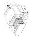
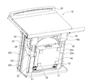
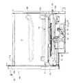
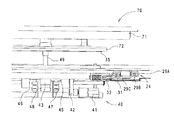
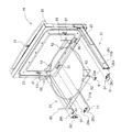
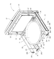
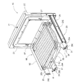
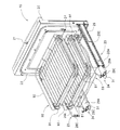
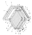
本発明の一実施形態に係る調理器を示し、扉開放2段バット載置状態の調理器の斜視図である。It is a perspective view of a cooking appliance which shows a cooking appliance concerning one embodiment of the present invention, and is in a state where a door is opened two-stage bat. 本発明の一実施形態に係る調理器を示し、扉開放ターンテーブル載置状態の調理器の斜視図である。It is a perspective view of a cooking appliance which shows a cooking appliance concerning one embodiment of the present invention, and is in a door open turntable placement state. 本発明の一実施形態に係る調理器を示し、扉開放バット載置状態の調理器の側面図である。It is a side view of the cooking appliance which shows the cooking appliance concerning one embodiment of the present invention, and is in a door open bat placement state. 本発明の一実施形態に係る調理器を示し、扉開放バット載置状態の調理器の説明図である。The cooking device which concerns on one Embodiment of this invention is shown, and it is explanatory drawing of the cooking device of a door open bat mounting state. 本発明の一実施形態に係る調理器を示し、扉開放上段バット途中停止状態の調理器の側面図である。It is a side view of the cooking appliance which shows the cooking appliance concerning one embodiment of the present invention, and is in the state where the door opening upper stage bat stops halfway. 本発明の一実施形態に係る調理器の正面図である。It is a front view of the cooking device concerning one embodiment of the present invention. 本発明の一実施形態に係る調理器を示し、調理器の底面方向の斜視図である。It is a perspective view of the bottom direction of a cooking appliance, showing a cooking appliance concerning one embodiment of the present invention. 本発明の一実施形態に係る調理器を示し、(A)は扉引き込み前の要部の斜視図、(B)は扉引き込み開始直前の要部の斜視図、(C)は扉引き込み開始直後の要部の斜視図、(D)は扉引き込み状態の要部の斜視図である。The cooker which concerns on one Embodiment of this invention is shown, (A) is a perspective view of the principal part before door drawing-in, (B) is a perspective view of the principal part just before door pull-in start, (C) is immediately after door pull-in start. (D) is a perspective view of the principal part of a door retracted state. 本発明の一実施形態に係る調理器を示し、ターンテーブルとターンテーブル駆動部との係合状態の要部の断面図である。FIG. 2 is a cross-sectional view of a main part in an engaged state between the turntable and the turntable driving unit, showing the cooking device according to the embodiment of the present invention. 本発明の一実施形態に係る調理器を示し、ターンテーブルとターンテーブル駆動部とが離間状態の要部の断面図である。The cooking device which concerns on one Embodiment of this invention is shown, and a turntable and a turntable drive part are sectional drawings of the principal part of a separation state. 本発明の一実施形態に係る調理器を示し、スライドロック状態の要部の正面図である。It is a front view of the principal part of the slide lock state which shows the cooking appliance concerning one embodiment of the present invention. 本発明の一実施形態に係る調理器を示し、スライドロック状態の要部の説明図である。The cooking device which concerns on one Embodiment of this invention is shown, and it is explanatory drawing of the principal part of a slide lock state. 本発明の一実施形態に係る調理器を示し、スライドロック状態の要部の拡大図である。The cooking device which concerns on one Embodiment of this invention is shown, and it is an enlarged view of the principal part of a slide lock state. 本発明の一実施形態に係る調理器を示し、スライドアンロック状態の要部の正面図である。It is a front view of the principal part of the cooking appliance concerning one embodiment of the present invention, and a slide unlocking state. 本発明の一実施形態に係る調理器を示し、スライドアンロック状態の要部の説明図である。The cooking device which concerns on one Embodiment of this invention is shown, and it is explanatory drawing of the principal part of a slide unlocked state. 本発明の一実施形態に係る調理器を示し、スライドアンロック状態の要部の拡大図である。The cooking device which concerns on one Embodiment of this invention is shown, and it is an enlarged view of the principal part of a slide unlocking state. 本発明の一実施形態に係る調理器を示し、扉にテーブル保持フレームを装着した状態の説明図である。It is explanatory drawing of the state which showed the cooking device which concerns on one Embodiment of this invention, and equipped the door with the table holding frame. 本発明の一実施形態に係る調理器を示し、扉にターンテーブルを保持した状態の説明図である。It is explanatory drawing of the state which showed the cooker which concerns on one Embodiment of this invention, and hold | maintained the turntable in the door. 本発明の一実施形態に係る調理器を示し、扉にターンテーブルを保持した状態の扉底面側の説明図である。It is explanatory drawing by the side of the door bottom face which shows the cooking appliance which concerns on one Embodiment of this invention, and hold | maintained the turntable in the door. 本発明の一実施形態に係る調理器を示し、扉に下段バットを保持した状態の説明図である。It is explanatory drawing of the state which showed the cooking device which concerns on one Embodiment of this invention, and hold | maintained the lower bat | bath on the door. 本発明の一実施形態に係る調理器を示し、扉にバット保持フレームを装着した状態の説明図である。It is explanatory drawing of the state which showed the cooking device which concerns on one Embodiment of this invention, and equipped the door with the bat holding frame. 本発明の一実施形態に係る調理器を示し、扉に上下2段のバットを保持した状態の説明図である。It is explanatory drawing of the state which showed the cooking device which concerns on one Embodiment of this invention, and hold | maintained the upper and lower two-stage bats on the door. 本発明の一実施形態に係る調理器を示し、扉に上下2段のバットを保持した状態の扉底面側の説明図である。It is explanatory drawing by the side of the door bottom face of the state which showed the cooker which concerns on one Embodiment of this invention, and hold | maintained the bat | bat of 2 steps | paragraphs on the top and bottom. 本発明の一実施形態に係る調理器を示し、上段バットにトングを係合させた状態の説明図である。It is explanatory drawing of the state which showed the cooking appliance which concerns on one Embodiment of this invention, and engaged the tongue with the upper stage bat. 本発明の一実施形態に係る調理器を示し、上段バットをトングで浮かせた状態の説明図である。It is explanatory drawing of the state which showed the cooking appliance which concerns on one Embodiment of this invention, and floated the upper stage bat with the tongue.

次に、本発明の一実施形態に係る調理器について、図面を参照して説明する。尚、以下に示す実施例は本発明の調理器における好適な具体例であり、技術的に好ましい種々の限定を付している場合もあるが、本発明の技術範囲は、特に本発明を限定する記載がない限り、これらの態様に限定されるものではない。また、以下に示す実施形態における構成要素は適宜、既存の構成要素等との置き換えが可能であり、かつ、他の既存の構成要素との組合せを含む様々なバリエーションが可能である。したがって、以下に示す実施形態の記載をもって、特許請求の範囲に記載された発明の内容を限定するものではない。   Next, the cooking device which concerns on one Embodiment of this invention is demonstrated with reference to drawings. In addition, although the Example shown below is a suitable specific example in the cooking device of this invention, and there may be various technically preferable restrictions, the technical scope of this invention limits this invention especially. Unless otherwise stated, the present invention is not limited to these embodiments. In addition, the constituent elements in the embodiments shown below can be appropriately replaced with existing constituent elements and the like, and various variations including combinations with other existing constituent elements are possible. Therefore, the description of the embodiment described below does not limit the contents of the invention described in the claims.

図1は本発明の一実施形態に係る調理器を示し、扉開放2段バット載置状態の調理器の斜視図、図2は本発明の一実施形態に係る調理器を示し、扉開放ターンテーブル載置状態の調理器の斜視図、図3は本発明の一実施形態に係る調理器を示し、扉開放バット載置状態の調理器の側面図、図4は本発明の一実施形態に係る調理器を示し、扉開放バット載置状態の調理器の説明図、図5は本発明の一実施形態に係る調理器を示し、扉開放上段バット途中停止状態の調理器の側面図、図6は本発明の一実施形態に係る調理器の正面図、図7は本発明の一実施形態に係る調理器を示し、調理器の底面方向の斜視図、図8は本発明の一実施形態に係る調理器を示し、図8(A)は扉引き込み前の要部の斜視図、図8(B)は扉引き込み開始直前の要部の斜視図、図8(C)は扉引き込み開始直後の要部の斜視図、図8(D)は扉引き込み状態の要部の斜視図、図9は本発明の一実施形態に係る調理器を示し、ターンテーブルとターンテーブル駆動部との係合状態の要部の断面図、図10は本発明の一実施形態に係る調理器を示し、ターンテーブルとターンテーブル駆動部とが離間状態の要部の断面図、図11は本発明の一実施形態に係る調理器を示し、スライドロック状態の要部の正面図、図12は本発明の一実施形態に係る調理器を示し、スライドロック状態の要部の説明図、図13は本発明の一実施形態に係る調理器を示し、スライドロック状態の要部の拡大図、図14は本発明の一実施形態に係る調理器を示し、スライドアンロック状態の要部の正面図、図15は本発明の一実施形態に係る調理器を示し、スライドアンロック状態の要部の説明図、図16は本発明の一実施形態に係る調理器を示し、スライドアンロック状態の要部の拡大図、図17は本発明の一実施形態に係る調理器を示し、扉にテーブル保持フレームを装着した状態の説明図、図18は本発明の一実施形態に係る調理器を示し、扉にターンテーブルを保持した状態の説明図、図19は本発明の一実施形態に係る調理器を示し、扉にターンテーブルを保持した状態の扉底面側の説明図、図20は本発明の一実施形態に係る調理器を示し、扉に下段バットを保持した状態の説明図、図21は本発明の一実施形態に係る調理器を示し、扉にバット保持フレームを装着した状態の説明図、図22は本発明の一実施形態に係る調理器を示し、扉に上下2段のバットを保持した状態の説明図、図23は本発明の一実施形態に係る調理器を示し、扉に上下2段のバットを保持した状態の扉底面側の説明図、図24は本発明の一実施形態に係る調理器を示し、上段バットにトングを係合させた状態の説明図、図25は本発明の一実施形態に係る調理器を示し、上段バットをトングで浮かせた状態の説明図である。   FIG. 1 shows a cooking device according to an embodiment of the present invention, and is a perspective view of the cooking device in a state where the door is opened in a two-stage bat. FIG. 2 shows the cooking device according to an embodiment of the present invention, and a door opening turn. 3 is a perspective view of a cooking device in a table-mounted state, FIG. 3 shows a cooking device according to one embodiment of the present invention, a side view of the cooking device in a door-opening bat mounting state, and FIG. 4 in one embodiment of the present invention. FIG. 5 is a side view of the cooking device in the state where the door is opened and the upper bat is stopped halfway. FIG. 5 is a diagram illustrating the cooking device according to the embodiment of the present invention. 6 is a front view of a cooking device according to an embodiment of the present invention, FIG. 7 is a perspective view of the cooking device according to an embodiment of the present invention, and is a bottom view of the cooking device, and FIG. 8 is an embodiment of the present invention. FIG. 8 (A) is a perspective view of the main part before the door is retracted, and FIG. 8 (B) is the main part immediately before the door is retracted. FIG. 8 (C) is a perspective view of the main part immediately after the start of the door retracting, FIG. 8 (D) is a perspective view of the main part in the door retracted state, and FIG. 9 is a cooking device according to one embodiment of the present invention. FIG. 10 is a cross-sectional view of the main part in an engaged state between the turntable and the turntable driving unit, and FIG. 10 shows a cooker according to an embodiment of the present invention, where the turntable and the turntable driving unit are in a separated state. FIG. 11 shows a cooking device according to one embodiment of the present invention, a front view of the main part in a slide lock state, and FIG. 12 shows a cooking device according to one embodiment of the present invention, in a slide lock state. FIG. 13 shows a cooking device according to one embodiment of the present invention, FIG. 14 is an enlarged view of the main portion in a slide lock state, and FIG. 14 shows a cooking device according to one embodiment of the present invention, and slides. The front view of the principal part in an unlocked state, FIG. 15 is one embodiment of the present invention FIG. 16 shows a cooking device according to an embodiment of the present invention, an enlarged view of the main part in the slide unlocked state, and FIG. 17 shows the cooking device according to the present invention. The explanatory view of the state which showed the cooking appliance concerning one embodiment, and equipped the door with the table holding frame, and Drawing 18 shows the cooking appliance concerning one embodiment of the present invention, and the explanatory view of the state where the door held the turntable FIG. 19 shows a cooking device according to an embodiment of the present invention, and is an explanatory view of the door bottom side in a state where a turntable is held on the door. FIG. 20 shows a cooking device according to an embodiment of the present invention, and the door. FIG. 21 shows a cooking device according to an embodiment of the present invention, FIG. 21 is an explanatory diagram of a state where a bat holding frame is attached to the door, and FIG. 22 shows an embodiment of the present invention. Shows the cooking device, and holds the upper and lower bats on the door. FIG. 23 shows a cooking device according to an embodiment of the present invention, FIG. 23 is an explanatory view of the bottom surface side of the door with the upper and lower bats held on the door, and FIG. 24 is an embodiment of the present invention. The cooker which concerns on a form, and the explanatory view of the state which engaged the tongue with the upper stage bat, FIG. 25: is the explanatory view of the state which showed the cooker which concerns on one Embodiment of this invention, and floated the upper stage bat with the tongue is there.

図1乃至図5において、本発明の調理器11は、被調理物をバーナの燃焼熱気によって加熱調理するオーブン調理と、被調理物をマグネトロンから照射されたマイクロ波によって加熱調理する電子レンジ調理と、を可能とした所謂コンビネーションレンジである。なお、図中、12は排気穴、13は燃焼ガスの供給管(図3,図5では接続部分のみ開示)である。   1 to 5, a cooking device 11 of the present invention includes an oven cooking that cooks an object to be cooked with combustion heat from a burner, and a microwave cooking that cooks an object to be cooked with microwaves irradiated from a magnetron. Is a so-called combination range. In the figure, 12 is an exhaust hole, and 13 is a combustion gas supply pipe (only the connection portion is disclosed in FIGS. 3 and 5).

また、バーナ本体(図示せず)を備えた調理器本体14は、外壁15と、前面に配置された操作部16と、庫内17を構成する内壁18と、庫内17の前面開口(開放端)17aを開閉する扉19と、を備えている。   The cooker body 14 provided with a burner body (not shown) includes an outer wall 15, an operation unit 16 disposed on the front surface, an inner wall 18 that forms the interior 17, and a front opening (open) in the interior 17. And a door 19 for opening and closing the end 17a.

扉19は、前面に開閉操作用の取手20が設けられている。この取手20の中央裏面付近には、扉19の閉成状態から開放状態とする際の解除スイッチ21が設けられている。また、扉19の裏面には、図6に示すように、庫内17の前面開口17aの外側で内壁18の前面縁部18aと当接するパッキン22が設けられている。さらに、本実施の形態における扉19は、その裏面側の下方寄り両側縁部付近と中央寄り下縁部付近の2箇所の計4箇所でガイドレール23,24によって支持されている。   The door 19 has a handle 20 for opening / closing operation on the front surface. A release switch 21 for changing the door 19 from the closed state to the open state is provided near the center rear surface of the handle 20. Further, as shown in FIG. 6, a packing 22 that contacts the front edge 18 a of the inner wall 18 outside the front opening 17 a of the interior 17 is provided on the rear surface of the door 19. Furthermore, the door 19 in the present embodiment is supported by the guide rails 23 and 24 at a total of four locations, two near the lower side edge on the back side and near the lower edge near the center.

扉19の裏面側下方寄り両側縁部に配置された一対のサイドスライドレール23は、三段の伸縮可能な外中内レール26A,26B,26Cを備えている(図11,図14に詳細図示)。最も外側(調理器本体14の内側)に位置して断面の大きい略コ字形状の外レール26Aは、一端から中レール26Bと内レール26Cとが出没可能となるように他端側が前面縁部18aから抜け止め状態で内壁18の外面又は外壁15の内面にスライド変位可能に支持されている。また、中レール26Bは外レール26Aとの間にボール27が介在され、このボール27によって外レール26Aの一端から出没可能となるように長手方向にスライド変位可能とされている。同様に、内レール26Cは、中レール26Bとの間にボール27が介在され、このボール27によって中レール26Bの一端から出没可能となるように長手方向にスライド変位可能とされている。さらに、外レール26Aは中レール26Bを、中レール26Bは内レール26Cを、それぞれ抜け止め状態で支持している。また、内レール26Cは、ブラケット25を介して一端側(先端側)で扉19の裏面を支持している。   A pair of side slide rails 23 arranged on both side edges near the lower side of the back side of the door 19 includes three-stage extendable outer / inner / outer rails 26A, 26B, and 26C (shown in detail in FIGS. 11 and 14). ). The outer rail 26A, which is located on the outermost side (inside the cooker main body 14) and has a large cross section, has a front edge at the other end so that the middle rail 26B and the inner rail 26C can protrude from one end. 18a is supported on the outer surface of the inner wall 18 or the inner surface of the outer wall 15 so as to be slidable. Further, a ball 27 is interposed between the middle rail 26B and the outer rail 26A, and the ball 27 is slidable in the longitudinal direction so that the ball 27 can protrude and retract from one end of the outer rail 26A. Similarly, a ball 27 is interposed between the inner rail 26C and the middle rail 26B, and the ball 27 can be slidably displaced in the longitudinal direction so that the ball 27 can protrude and retract from one end of the middle rail 26B. Further, the outer rail 26A supports the middle rail 26B, and the middle rail 26B supports the inner rail 26C in a retaining state. Further, the inner rail 26 </ b> C supports the back surface of the door 19 on one end side (front end side) via the bracket 25.

扉19の裏面側下方寄り下縁部に配置された一対のアンダースライドレール24は、三段の伸縮可能な外中内レール29A,29B,29Cを備えている(図11,図13,図14,図16に詳細図示)。最も外側(調理器本体14の内側)に位置して断面の大きい略コ字形状の外レール29Aは、一端から中レール29Bと内レール29Cとが出没可能となるように他端側が前面縁部18aから抜け止め状態で内壁18の外面又は外壁15の内面にスライド変位可能に支持されている。また、中レール29Bは外レール29Aとの間にボール30が介在され、このボール30によって外レール29Aの一端から出没可能となるように長手方向にスライド変位可能とされている。同様に、内レール29Cは、中レール29Bとの間にボール30が介在され、このボール30によって中レール29Bの一端から出没可能となるように長手方向にスライド変位可能とされている。さらに、外レール29Aは中レール29Bを、中レール29Bは内レール29Cを、それぞれ抜け止め状態で支持している。また、内レール29Cは、ブラケット28を介して一端側(先端側)で扉19の裏面を支持している。   The pair of underslide rails 24 disposed on the lower edge of the door 19 on the lower side on the back side includes three stages of extendable inner / outer inner rails 29A, 29B, and 29C (FIGS. 11, 13, and 14). , Shown in detail in FIG. The outer rail 29A, which is located on the outermost side (inside the cooker main body 14) and has a substantially U-shaped cross section, has a front edge at the other end so that the middle rail 29B and the inner rail 29C can protrude from one end. 18a is supported on the outer surface of the inner wall 18 or the inner surface of the outer wall 15 so as to be slidable. Further, a ball 30 is interposed between the middle rail 29B and the outer rail 29A, and the ball 30 can be slidably displaced in the longitudinal direction so that the ball 30 can protrude from one end of the outer rail 29A. Similarly, the ball 30 is interposed between the inner rail 29 </ b> C and the middle rail 29 </ b> B, and the ball 30 can be slidably displaced in the longitudinal direction so that the ball 30 can protrude from one end of the middle rail 29 </ b> B. Further, the outer rail 29A supports the middle rail 29B, and the middle rail 29B supports the inner rail 29C in a retaining state. The inner rail 29 </ b> C supports the back surface of the door 19 on one end side (front end side) via the bracket 28.

一方、内レール29Cの他端側には平板状の引込プレート(プレート部材)31が固定されている。この引込プレート31は、図7に示すように、内レール29Cの他端側に略水平状態で固定されて、内レール29Cのスライド変位に連動して変位する。また、引込プレート31の一端(先端)は扉19が閉成状態にあるときの扉19の開放を阻止する際に利用される(詳細は後述)。さらに、引込プレート31の他端(後端)は、中途部から端部に向かう程に先細りとなるように内側端縁が傾斜され、その中途部の内側端縁には外向きに拡開する略凹形状のガイド溝31aが形成されている。   On the other hand, a flat lead-in plate (plate member) 31 is fixed to the other end side of the inner rail 29C. As shown in FIG. 7, the pull-in plate 31 is fixed to the other end side of the inner rail 29C in a substantially horizontal state, and is displaced in conjunction with the sliding displacement of the inner rail 29C. Further, one end (tip) of the drawing plate 31 is used to prevent the door 19 from being opened when the door 19 is in the closed state (details will be described later). Further, the other end (rear end) of the pull-in plate 31 is inclined so that the inner end edge is tapered toward the end part from the midway part, and expands outward to the inner end edge of the midway part. A substantially concave guide groove 31a is formed.

また、調理器本体14の奥側には、両端にバネ付勢された引込ローラ(ローラ体)32を保持したローラ保持プレート33が配置されている。これにより、扉19を開放状態からスライド変位させて閉成しようと押入れ操作すると、図8(A),(B)に示すように、その閉成完了直前で引込ローラ32が引込プレート31の他端側の内側端縁に弾性接触し、図8(C)に示すように、更なる扉19の押入れ操作によってガイド溝31aに引込ローラ32が位置したときに、そのガイド作用と弾性力とによって、図8(D)に示すように、引込ローラ32がガイド溝31aの底縁にガイドされ、扉19の全体を引き込むことができる。なお、図7において、符号34はアンダースライドレール24の下面を支持する支持プレートである。   Further, on the back side of the cooker main body 14, a roller holding plate 33 holding a drawing roller (roller body) 32 that is spring-biased at both ends is arranged. As a result, when the door 19 is slid from the open state to close the door 19 as shown in FIGS. 8 (A) and 8 (B), the pull-in roller 32 moves away from the pull-in plate 31 immediately before the closing is completed. When the pulling roller 32 is positioned in the guide groove 31a by further pressing operation of the door 19, as shown in FIG. 8C, the guide action and elastic force are brought into elastic contact with the inner edge of the end side. As shown in FIG. 8D, the drawing roller 32 is guided by the bottom edge of the guide groove 31a, and the entire door 19 can be drawn. In FIG. 7, reference numeral 34 denotes a support plate that supports the lower surface of the underslide rail 24.

一方、内壁18の底面(底板)の略中央には、下方に向けて凹陥された凹陥部18bが形成されており、この凹陥部18bには回転かつ昇降可能な円盤状の駆動テーブル35が配置されており、凹陥部18bの下方空間には駆動テーブル35を回転及び昇降させるターンテーブル駆動部40が配置されている。   On the other hand, a recessed portion 18b that is recessed downward is formed at the approximate center of the bottom surface (bottom plate) of the inner wall 18, and a disk-shaped drive table 35 that can be rotated and raised is disposed in the recessed portion 18b. A turntable drive unit 40 that rotates and raises and lowers the drive table 35 is disposed in a space below the recessed portion 18b.

ターンテーブル駆動部40は、駆動テーブル35を回転させる回転装置部と、駆動テーブル35を昇降させる昇降装置部と、を備えている。尚、回転装置部に関しては、駆動テーブル35が上昇している状態のときに所定方向等に駆動テーブル35を回転させるものであり、その動力伝達方式や回転制御方式等は公知の技術を適用することができる。したがって、以下の説明では、昇降装置部をターンテーブル駆動部40として説明する。   The turntable driving unit 40 includes a rotating device unit that rotates the driving table 35 and an elevating device unit that moves the driving table 35 up and down. As for the rotating device unit, the drive table 35 is rotated in a predetermined direction or the like when the drive table 35 is raised, and a known technique is applied to the power transmission method and the rotation control method. be able to. Therefore, in the following description, the lifting device unit will be described as the turntable driving unit 40.

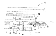
ターンテーブル駆動部40は、図9乃至図16に示すように、駆動モータ41と、駆動モータ41の回転駆動をベルト42を介して伝達される昇降カム43と、昇降カム43の回転位置に応じて回動する昇降アーム44と、昇降カム43と同軸上に設けられて偏心位置(位相)がずれた上昇偏心カム45及び下降偏心カム46と、上昇偏心カム45及び下降偏心カム46の回転位置によってON/OFFされる上昇検出スイッチ47及び下降検出スイッチ48と、昇降アーム44の先端と係合して回転軸49と一体に駆動テーブル35を昇降させる昇降部50と、昇降部50に設けられてその上昇時に引込プレート31の一端(先端)と係合するロック爪51と、ターンテーブル70を回転させるターンテーブル回転駆動モータ52と、を備えている。   As shown in FIGS. 9 to 16, the turntable drive unit 40 corresponds to the drive motor 41, the lift cam 43 that transmits the rotational drive of the drive motor 41 via the belt 42, and the rotation position of the lift cam 43. Rotating position of the raising and lowering eccentric cam 45 and the lowering eccentric cam 46 provided on the same axis as the raising and lowering arm 44, the raising and lowering cam 43 and shifted in eccentric position (phase), and the raising and lowering eccentric cams 45 and 46. The lift detection switch 47 and the decrease detection switch 48 which are turned ON / OFF by the lift, the lift 50 which is engaged with the tip of the lift arm 44 and lifts the drive table 35 integrally with the rotary shaft 49, and the lift 50 are provided. A lock claw 51 that engages with one end (tip) of the pull-in plate 31 when the lever is raised, and a turntable rotation drive motor 52 that rotates the turntable 70. To have.

このような構成においては、扉19が前面開口17aを閉成すると、図示を略する扉検出スイッチが作動して駆動モータ41を駆動させ、駆動テーブル35を上昇させると同時にロック爪51を上昇させる。   In such a configuration, when the door 19 closes the front opening 17a, a door detection switch (not shown) is actuated to drive the drive motor 41 to raise the drive table 35 and simultaneously raise the lock claw 51. .

駆動テーブル35が上昇すると、ターンテーブル70の丸バット本体71の底面に設けられたクラッチ部72に駆動テーブル35が係合し、駆動テーブル35の回転をターンテーブル70に伝達することができる。   When the drive table 35 is raised, the drive table 35 is engaged with the clutch portion 72 provided on the bottom surface of the round bat main body 71 of the turntable 70, and the rotation of the drive table 35 can be transmitted to the turntable 70.

また、ロック爪51が上昇すると、引込プレート31の一端(先端)と係合し、引込プレート31の扉開放方向のスライド変位が阻止される。   Further, when the lock claw 51 rises, it engages with one end (tip) of the pull-in plate 31, and the slide displacement of the pull-in plate 31 in the door opening direction is prevented.

また、駆動モータ41が駆動すると、上昇偏心カム45と下降偏心カム46の回転位置によって上昇検出スイッチ47と下降検出スイッチ48とが逆転状態でON/OFFする。扉19が前面開口17aを閉成すると、駆動テーブル35とターンテーブル70との係合状態及びロック爪51と引込プレート31との係合状態を検出することで操作部16の操作による調理開始指令に対して調理を開始(例えば、バーナやマグネトロンの作動)させる。   Further, when the drive motor 41 is driven, the ascending detection switch 47 and the descending detection switch 48 are turned ON / OFF in a reverse state depending on the rotational positions of the ascending eccentric cam 45 and the descending eccentric cam 46. When the door 19 closes the front opening 17a, the cooking start command by the operation of the operation unit 16 is detected by detecting the engagement state between the drive table 35 and the turntable 70 and the engagement state between the lock claw 51 and the pull-in plate 31. Start cooking (for example, operating a burner or magnetron).

また、解除スイッチ21をONすると、調理状態の停止(例えば、バーナやマグネトロンの作動停止)すると共に、駆動モータ41が駆動してターンテーブル70から駆動テーブル35が退避(下降)すると同時に、引込プレート31からロック爪51が退避(下降)し、扉19の引き出し方向のスライド変位を許容して前面開口17aが開放される。   When the release switch 21 is turned on, the cooking state is stopped (for example, the operation of the burner or the magnetron is stopped), the drive motor 41 is driven, and the drive table 35 is retracted (lowered) from the turntable 70. The lock claw 51 is retracted (lowered) from 31 and the front opening 17a is opened while allowing the sliding displacement of the door 19 in the pulling direction.

ところで、本実施の形態では、図17乃至図25に示すように、ターンテーブル70は、テーブル保持フレーム60によって保持され、扉19のスライド変位に連動するように構成されている。これにより、ターンテーブル70に対する調理物の載置や取り出し、調理途中での調理具合の確認等を庫内17を覗き込むことなく行なうことができる。   By the way, in this Embodiment, as shown in FIG. 17 thru | or FIG. 25, the turntable 70 is hold | maintained by the table holding frame 60, and is comprised so that it may interlock | cooperate with the sliding displacement of the door 19. FIG. Thereby, it is possible to place and take out the food on the turntable 70, check the cooking condition during cooking, and the like without looking into the inside of the cabinet 17.

このテーブル保持フレーム60は、その一端が扉19の裏面下方に設けられた下フック36と係合して保持され、その他端には庫内17の底面(内壁18の底面)上を転動(走行)す円柱状ローラ61が設けられている。また、テーブル保持フレーム60は、ターンテーブル70の丸バット本体71の底面を浮遊状態で支持(保持)する支持突起62と、ターンテーブル70よりも高い位置で角バット90の角バット本体91を支持する支持フレーム部63と、を備えている。   One end of the table holding frame 60 is held by engaging with a lower hook 36 provided below the back surface of the door 19, and the other end rolls on the bottom surface of the interior 17 (the bottom surface of the inner wall 18) ( A cylindrical roller 61 is provided. The table holding frame 60 also supports a support protrusion 62 that supports (holds) the bottom surface of the round bat body 71 of the turntable 70 in a floating state, and supports the corner bat body 91 of the corner bat 90 at a position higher than the turntable 70. And a support frame portion 63.

これにより、テーブル保持フレーム60はターンテーブル70又は角バット90の両方を同時に保持することができる。なお、実際の調理時には何れか一方を支持するのが一般的である。   Thereby, the table holding frame 60 can hold both the turntable 70 and the square bat 90 simultaneously. In addition, it is common to support either one at the time of actual cooking.

また、この角バット90は、同一のものを上下2段積みすることが可能となっている。この際、下段の角バット90には、一端が扉19の裏面中途部に設けられた上フック37と係合するバット保持フレーム80の他端の脚部81を支持する。   In addition, the square bat 90 can be stacked in two upper and lower stages. At this time, the lower corner bat 90 supports the leg portion 81 of the other end of the bat holding frame 80 that engages with the upper hook 37 provided at one end of the rear surface of the door 19.

バット保持フレーム80は、上段の角バット90の裏面側周縁を支持すると共に後端側を開放しており、例えば、図4に示す状態(実際には被調理物を載置)で扉19を閉成して調理を行ない、図5に示すように、その途中又は調理終了後に扉19をスライド変位させると、下段側の角バット90は扉19の開放位置と同位置にまで引き出し、上段側の角バット90は途中までの引き出しとすることができる。   The butt holding frame 80 supports the peripheral edge on the back side of the upper corner bat 90 and opens the rear end side. For example, the butt holding frame 80 holds the door 19 in the state shown in FIG. As shown in FIG. 5, when the door 19 is slid and displaced during or after cooking, the lower corner bat 90 is pulled out to the same position as the opening position of the door 19 as shown in FIG. The square bat 90 can be a halfway drawer.

これにより、被調理物の調理具合の確認や取り出しを行なう際に、上段の角バット90が作業の邪魔となり難くすることができる。   Thereby, when confirming and taking out the cooking condition of the object to be cooked, the upper corner bat 90 can be made difficult to interfere with the work.

なお、扉19を閉成した際には、上下各段の角バット90は、庫内17の内壁18の両側面に形成されたバットガイド18c,18dによって支持させることができる。これにより、各保持フレーム60,80を用いずに、庫内17に角バット90を支持させることも可能であると共に、扉19の開閉に連動して押し入れ・引き出しを可能とすることができる。この際、上述した上段に関しては、例えば、バットガイド18dと角バット90との高さ方向の位置をバット保持フレーム80の高さによって調整することで、摩擦抵抗等によって途中までの引き出しを可能とする。また、バット保持フレーム80の後端を開放しているため、バット保持フレーム80と角バット本体91との間で雌雄の異なる係合部を設けたり、バットガイド18dの先端側を上向き(数ミリ)として摩擦抵抗を高くするなど、その方法は適宜とすることができる。さらに、バット保持フレーム80の後端の開放を切り替え可能とし、必要に応じて全部引き出しと途中引き出しとを切り替え可能とすることも可能である。   When the door 19 is closed, the upper and lower corner bats 90 can be supported by butt guides 18 c and 18 d formed on both side surfaces of the inner wall 18 of the interior 17. Thus, the square bat 90 can be supported in the interior 17 without using the holding frames 60, 80, and can be pushed in and pulled out in conjunction with the opening and closing of the door 19. At this time, with respect to the above-described upper stage, for example, by adjusting the height direction position of the bat guide 18d and the square bat 90 according to the height of the bat holding frame 80, it is possible to pull out partway due to frictional resistance or the like. To do. In addition, since the rear end of the bat holding frame 80 is opened, different male and female engaging portions are provided between the bat holding frame 80 and the square bat main body 91, or the front end side of the bat guide 18d faces upward (several millimeters). The method can be appropriately determined, for example, by increasing the frictional resistance. Furthermore, it is possible to switch the opening of the rear end of the bat holding frame 80, and to switch between full drawer and halfway drawer as required.

このように、本発明によれば、複数のバット(70,90)を組み合わせて設置することができ、バリエーションに富んだ調理に貢献することができる。また、図24,図25に示すように、所謂トング38を用いた各バット70,90の出し入れも可能である。   Thus, according to the present invention, a plurality of bats (70, 90) can be installed in combination, which can contribute to cooking rich in variations. Further, as shown in FIGS. 24 and 25, the bats 70 and 90 can be put in and out using so-called tongs 38.

このように、本発明の調理器にあっては、庫内17の側面よりも外側の扉19の両側縁に一端が保持されかつ他端が調理器本体14の内部に支持された一対のサイドスライドレール23と、庫内17の底面よりも外側の扉19の下縁に一端が保持されかつ他端が調理器本体14の内部に支持されたアンダースライドレール24と、を備え、サイドスライドレール23とアンダースライドレール24とで扉19をスライド変位することで前面開口17aを開閉することにより、庫内17の調理物の調理状態を容易に確認することができる。   Thus, in the cooking device of the present invention, one end is held at both side edges of the door 19 outside the side surface of the interior 17 and the other end is supported inside the cooking device body 14. A slide rail 23, and an under slide rail 24 having one end held at the lower edge of the door 19 outside the bottom surface of the interior 17 and the other end supported inside the cooker body 14, and a side slide rail By opening and closing the front opening 17a by sliding and displacing the door 19 between the door 23 and the underslide rail 24, the cooking state of the cooked food in the cabinet 17 can be easily confirmed.

この際、サイドスライドレール23とアンダースライドレール24とは、前面開口17aよりも外側を取り巻き状態でシールするように扉19の裏面に設けられたパッキン22よりも外方に配置されているため、庫内17から電磁波の漏れを抑制することができる。   At this time, the side slide rail 23 and the under slide rail 24 are disposed outward from the packing 22 provided on the back surface of the door 19 so as to seal the outer side of the front opening 17a in a wound state. The leakage of electromagnetic waves from the inside 17 can be suppressed.

また、アンダースライドレール24は、ターンテーブル駆動部40を避けるように均等間隔で挟む位置に設けられているため、扉19からの荷重を均等に分散することができ、しかも扉19の開閉を容易に行なうことができる。   Further, since the underslide rails 24 are provided at positions sandwiched at equal intervals so as to avoid the turntable drive unit 40, the load from the door 19 can be evenly distributed, and the door 19 can be easily opened and closed. Can be done.

また、ターンテーブル駆動部40は、扉19が前面開口17aを開放している際にはターンテーブル70から退避して非回転状態にあり、扉19が前面開口17aを閉成している際にはターンテーブル70と係合して回転状態にあるため、扉19が前面開口17aを開放している際にはターンテーブル駆動部40がターンテーブル70から退避して非回転状態にあることから、ターンテーブル70の引き出し等を許容することができる。   Further, the turntable driving unit 40 is retracted from the turntable 70 when the door 19 opens the front opening 17a and is in a non-rotating state, and when the door 19 closes the front opening 17a. Is engaged with the turntable 70 and is in a rotating state, so when the door 19 opens the front opening 17a, the turntable driving unit 40 is retracted from the turntable 70 and is in a non-rotating state. The drawer of the turntable 70 can be allowed.

この際、ターンテーブル駆動部40は、扉19が閉成している際には扉19の開放をロックしているため、扉19を閉成してターンテーブル駆動部40がターンテーブル70を駆動させる状態にあるときに、不測に扉19を開放させることを抑制することができる。   At this time, since the turntable drive unit 40 locks the opening of the door 19 when the door 19 is closed, the turntable drive unit 40 drives the turntable 70 by closing the door 19. It is possible to prevent the door 19 from being opened unexpectedly when it is in the state of being activated.

さらに、扉19は、前面開口17aを閉成しているときにターンテーブル70からターンテーブル駆動部40を退避させると同時に扉19の開放ロック状態を解除する解除スイッチ21を備えていることにより、扉19を開放させる際には、ロックを解除させない限り不測に開放してしまうことを抑制することができる。   Furthermore, the door 19 includes a release switch 21 that retracts the turntable driving unit 40 from the turntable 70 when the front opening 17a is closed, and at the same time releases the unlocked lock state of the door 19. When the door 19 is opened, it is possible to prevent the door 19 from being opened unexpectedly unless the lock is released.

また、扉19は前面開口17aを閉成しているときに前面開口17aと対向する裏面との相対位置が平行に変化するように調理器本体14に対してスライド変位可能に支持され、ターンテーブル70は扉19の開閉に伴うスライド変位に連動して変位するように扉19に支持されているため、扉19をスライドさせて前面開口17aを開閉させる際にターンテーブル70とターンテーブル駆動部40との係合状態を連動させることができ、ターンテーブル70とターンテーブル駆動部40とが係合状態となったまま扉19をスライドさせることを抑制することができる。   The door 19 is slidably supported with respect to the cooker body 14 so that the relative position between the front opening 17a and the back surface facing the door 19 changes in parallel when the front opening 17a is closed. 70 is supported by the door 19 so as to be displaced in conjunction with the sliding displacement associated with the opening and closing of the door 19. Therefore, when the door 19 is slid to open and close the front opening 17 a, the turntable 70 and the turntable driving unit 40. Can be interlocked, and the sliding of the door 19 while the turntable 70 and the turntable driving unit 40 are in the engaged state can be suppressed.

また、そのスライドロックをターンテーブル駆動部40の昇降に連動させてアンダースライドレール24のスライドを機械的にロック爪51でロックさせることにより、安価かつ簡素な構成で不測に扉19がスライド変位してしまうことを抑制することができる。   Further, the slide lock is interlocked with the raising and lowering of the turntable drive unit 40, and the slide of the underslide rail 24 is mechanically locked by the lock claw 51, so that the door 19 slides unexpectedly with an inexpensive and simple configuration. Can be suppressed.

11…調理器
12…排気穴
13…ホース
14…調理器本体
15…外壁
16…操作部
17…庫内
17a…前面開口(開放端)
18…内壁
18a…前面縁部
18b…凹陥部
18c…バットガイド
18d…バットガイド
19…扉
20…ノブ
21…解除スイッチ
22…パッキン
23…サイドスライドレール
24…アンダースライドレール
25…ブラケット
26A…外レール
26B…中レール
26C…内レール
27…ボール
28…ブラケット
29A…外レール
29B…中レール
29C…内レール
30…ボール
31…引込プレート(プレート部材)
31a…ガイド溝
32…引込ローラ(ローラ体)
33…ローラ保持プレート
34…支持プレート
35…駆動テーブル
36…下フック
37…上フック
38…トング
40…ターンテーブル駆動部
41…駆動モータ
42…ベルト
43…昇降カム
44…昇降アーム
45…上昇偏心カム
46…下降偏心カム
47…上昇検出スイッチ
48…下降検出スイッチ
49…回転軸
50…昇降部
51…ロック爪
52…ターンテーブル回転駆動モータ
60…テーブル保持フレーム
61…円柱状ローラ
62…支持突起
63…支持フレーム
70…ターンテーブル
71…丸バット
72…クラッチ部
80…バット保持フレーム
81…脚部
90…角バット
91…角バット本体
92…網皿
DESCRIPTION OF SYMBOLS 11 ... Cooker 12 ... Exhaust hole 13 ... Hose 14 ... Cooker main body 15 ... Outer wall 16 ... Operation part 17 ... Inside 17a ... Front opening (open end)
DESCRIPTION OF SYMBOLS 18 ... Inner wall 18a ... Front edge 18b ... Recessed part 18c ... Butt guide 18d ... Butt guide 19 ... Door 20 ... Knob 21 ... Release switch 22 ... Packing 23 ... Side slide rail 24 ... Under slide rail 25 ... Bracket 26A ... Outer rail 26B ... middle rail 26C ... inner rail 27 ... ball 28 ... bracket 29A ... outer rail 29B ... middle rail 29C ... inner rail 30 ... ball 31 ... retraction plate (plate member)
31a ... guide groove 32 ... drawing roller (roller body)
33 ... Roller holding plate 34 ... Support plate 35 ... Drive table 36 ... Lower hook 37 ... Upper hook 38 ... Tongue 40 ... Turntable drive unit 41 ... Drive motor 42 ... Belt 43 ... Lifting cam 44 ... Lifting arm 45 ... Lifting eccentric cam 46 ... Decline eccentric cam 47 ... Ascent detection switch 48 ... Decline detection switch 49 ... Rotating shaft 50 ... Elevating part 51 ... Lock claw 52 ... Turntable rotation drive motor 60 ... Table holding frame 61 ... Cylindrical roller 62 ... Supporting protrusion 63 ... Support frame 70 ... Turntable 71 ... Round bat 72 ... Clutch part 80 ... Butt holding frame 81 ... Leg part 90 ... Square bat 91 ... Square bat body 92 ... Net tray

Claims (4)

筐体形状の調理器本体と、該調理器本体の内部に形成されて被調理物を加熱調理するために前面に開放する庫内と、該庫内の開放端を開閉する扉と、前記庫内の底面中央付近で回転するターンテーブルと、前記庫内の前記底面よりも外側の前記調理器本体の内部に配置されて前記ターンテーブルを回転させるターンテーブル駆動部と、を備え、
前記ターンテーブル駆動部は、前記扉が前記開放端を開放している際には前記ターンテーブルから退避して非回転状態にあり、前記扉が前記開放端を閉成している際には前記ターンテーブルと係合して回転状態にあることを特徴とする調理器。
A cooker body having a casing shape, a chamber that is formed inside the cooker body and opens to the front in order to cook the food to be cooked, a door that opens and closes an open end in the chamber, and the warehouse A turntable that rotates in the vicinity of the bottom center in the inside, and a turntable drive unit that is arranged inside the cooker body outside the bottom surface in the warehouse and rotates the turntable,
The turntable driving unit is retracted from the turntable when the door opens the open end and is in a non-rotating state, and the door closes the open end when the door is closed. A cooker characterized by being in a rotating state by engaging with a turntable.
前記ターンテーブル駆動部は、前記扉が閉成している際には前記扉の開放をロックすることを特徴とする請求項1に記載の調理器。   The cooker according to claim 1, wherein the turntable drive unit locks the opening of the door when the door is closed. 前記扉は、前記開放端を閉成しているときに前記ターンテーブルから前記ターンテーブル駆動部を退避させると同時に前記扉の開放ロック状態を解除する解除スイッチを備えていることを特徴とする請求項1又は請求項2に記載の調理器。   The said door is provided with the release switch which cancels | releases the open lock state of the said door simultaneously with retracting the said turntable drive part from the said turntable when the said open end is closed. The cooker of Claim 1 or Claim 2. 前記扉は前記開放端を閉成しているときに該開放端と対向する裏面との相対位置が平行に変化するように前記調理器本体に対してスライド変位可能に支持され、前記ターンテーブルは前記扉の開閉に伴うスライド変位に連動して変位するように前記扉に支持され、ていることを特徴とする請求項1乃至請求項3の何れかに記載の調理器。   The door is slidably supported with respect to the cooker body so that the relative position between the open end and the back surface facing the open end changes in parallel when the open end is closed, and the turntable is The cooker according to any one of claims 1 to 3, wherein the cooker is supported by the door so as to be displaced in conjunction with a slide displacement accompanying opening and closing of the door.
JP2011245061A 2011-11-09 2011-11-09 Cooking device Expired - Fee Related JP5830356B2 (en)

Priority Applications (1)

Application Number Priority Date Filing Date Title
JP2011245061A JP5830356B2 (en) 2011-11-09 2011-11-09 Cooking device

Applications Claiming Priority (1)

Application Number Priority Date Filing Date Title
JP2011245061A JP5830356B2 (en) 2011-11-09 2011-11-09 Cooking device

Publications (2)

Publication Number Publication Date
JP2013100945A true JP2013100945A (en) 2013-05-23
JP5830356B2 JP5830356B2 (en) 2015-12-09

Family

ID=48621710

Family Applications (1)

Application Number Title Priority Date Filing Date
JP2011245061A Expired - Fee Related JP5830356B2 (en) 2011-11-09 2011-11-09 Cooking device

Country Status (1)

Country Link
JP (1) JP5830356B2 (en)

Cited By (1)

* Cited by examiner, † Cited by third party
Publication number Priority date Publication date Assignee Title
WO2016035833A1 (en) * 2014-09-04 2016-03-10 シャープ株式会社 Cooking device

Citations (2)

* Cited by examiner, † Cited by third party
Publication number Priority date Publication date Assignee Title
JPS56109295U (en) * 1980-01-24 1981-08-24
JP2005188880A (en) * 2003-12-26 2005-07-14 Matsushita Electric Ind Co Ltd Heating cooker

Patent Citations (2)

* Cited by examiner, † Cited by third party
Publication number Priority date Publication date Assignee Title
JPS56109295U (en) * 1980-01-24 1981-08-24
JP2005188880A (en) * 2003-12-26 2005-07-14 Matsushita Electric Ind Co Ltd Heating cooker

Cited By (2)

* Cited by examiner, † Cited by third party
Publication number Priority date Publication date Assignee Title
WO2016035833A1 (en) * 2014-09-04 2016-03-10 シャープ株式会社 Cooking device
US10172188B2 (en) 2014-09-04 2019-01-01 Sharp Kabushiki Kaisha Cooking heater

Also Published As

Publication number Publication date
JP5830356B2 (en) 2015-12-09

Similar Documents

Publication Publication Date Title
KR102474912B1 (en) Refrigerator
JP4027325B2 (en) Cooker
JP4280783B2 (en) Door-opening and closing method and apparatus for drawer-type cooking device
KR102542609B1 (en) Refrigerator
US7994457B2 (en) Drawer-type cooking device
JP5094238B2 (en) Lifting cabinet
KR200465383Y1 (en) Table having kitchen utensil
JP5830356B2 (en) Cooking device
JP5830358B2 (en) Cooking device
JP5895251B2 (en) A cooker equipped with an oven-cooking function using the combustion hot air of a gas burner
JP5830357B2 (en) Cooking device
JP5819707B2 (en) Cooking device
CN106172563A (en) The baking box that a kind of baking tray can automatically move out
KR20190120881A (en) An Oven Equipped with Easy-Elevating Tray
RU2303749C2 (en) Shelf device for oven
KR102586889B1 (en) Refrigerator
KR100664052B1 (en) Refrigerator having basket lift apparatus
WO2017049622A1 (en) Microwave heating apparatus
KR102617684B1 (en) Refrigerator
JP4293171B2 (en) Lifting storage device
CN218651485U (en) Dining table
KR100212863B1 (en) Microwave oven
KR100212862B1 (en) Microwave oven
JP2005188800A (en) Microwave oven
EP2026013A1 (en) Domestic appliance comprising pullout door carriage and traction-assisting mechanism

Legal Events

Date Code Title Description
RD01 Notification of change of attorney

Free format text: JAPANESE INTERMEDIATE CODE: A7421

Effective date: 20140128

A621 Written request for application examination

Free format text: JAPANESE INTERMEDIATE CODE: A621

Effective date: 20140710

A977 Report on retrieval

Free format text: JAPANESE INTERMEDIATE CODE: A971007

Effective date: 20150417

A131 Notification of reasons for refusal

Free format text: JAPANESE INTERMEDIATE CODE: A131

Effective date: 20150602

A711 Notification of change in applicant

Free format text: JAPANESE INTERMEDIATE CODE: A711

Effective date: 20150729

A521 Written amendment

Free format text: JAPANESE INTERMEDIATE CODE: A523

Effective date: 20150731

TRDD Decision of grant or rejection written
A01 Written decision to grant a patent or to grant a registration (utility model)

Free format text: JAPANESE INTERMEDIATE CODE: A01

Effective date: 20151020

A61 First payment of annual fees (during grant procedure)

Free format text: JAPANESE INTERMEDIATE CODE: A61

Effective date: 20151026

R150 Certificate of patent or registration of utility model

Ref document number: 5830356

Country of ref document: JP

Free format text: JAPANESE INTERMEDIATE CODE: R150

LAPS Cancellation because of no payment of annual fees