JP2011113039A - 光導波路装置及びその製造方法 - Google Patents
光導波路装置及びその製造方法 Download PDFInfo
- Publication number
- JP2011113039A JP2011113039A JP2009271837A JP2009271837A JP2011113039A JP 2011113039 A JP2011113039 A JP 2011113039A JP 2009271837 A JP2009271837 A JP 2009271837A JP 2009271837 A JP2009271837 A JP 2009271837A JP 2011113039 A JP2011113039 A JP 2011113039A
- Authority
- JP
- Japan
- Prior art keywords
- optical waveguide
- light
- path conversion
- optical path
- inclined surface
- Prior art date
- Legal status (The legal status is an assumption and is not a legal conclusion. Google has not performed a legal analysis and makes no representation as to the accuracy of the status listed.)
- Granted
Links
Images
Classifications
-
- G—PHYSICS
- G02—OPTICS
- G02B—OPTICAL ELEMENTS, SYSTEMS OR APPARATUS
- G02B6/00—Light guides; Structural details of arrangements comprising light guides and other optical elements, e.g. couplings
- G02B6/24—Coupling light guides
- G02B6/42—Coupling light guides with opto-electronic elements
- G02B6/43—Arrangements comprising a plurality of opto-electronic elements and associated optical interconnections
-
- G—PHYSICS
- G02—OPTICS
- G02B—OPTICAL ELEMENTS, SYSTEMS OR APPARATUS
- G02B6/00—Light guides; Structural details of arrangements comprising light guides and other optical elements, e.g. couplings
- G02B6/10—Light guides; Structural details of arrangements comprising light guides and other optical elements, e.g. couplings of the optical waveguide type
- G02B6/12—Light guides; Structural details of arrangements comprising light guides and other optical elements, e.g. couplings of the optical waveguide type of the integrated circuit kind
- G02B2006/12083—Constructional arrangements
- G02B2006/12104—Mirror; Reflectors or the like
-
- G—PHYSICS
- G02—OPTICS
- G02B—OPTICAL ELEMENTS, SYSTEMS OR APPARATUS
- G02B6/00—Light guides; Structural details of arrangements comprising light guides and other optical elements, e.g. couplings
- G02B6/10—Light guides; Structural details of arrangements comprising light guides and other optical elements, e.g. couplings of the optical waveguide type
- G02B6/12—Light guides; Structural details of arrangements comprising light guides and other optical elements, e.g. couplings of the optical waveguide type of the integrated circuit kind
- G02B6/13—Integrated optical circuits characterised by the manufacturing method
- G02B6/138—Integrated optical circuits characterised by the manufacturing method by using polymerisation
-
- G—PHYSICS
- G02—OPTICS
- G02B—OPTICAL ELEMENTS, SYSTEMS OR APPARATUS
- G02B6/00—Light guides; Structural details of arrangements comprising light guides and other optical elements, e.g. couplings
- G02B6/24—Coupling light guides
- G02B6/42—Coupling light guides with opto-electronic elements
- G02B6/4201—Packages, e.g. shape, construction, internal or external details
- G02B6/4204—Packages, e.g. shape, construction, internal or external details the coupling comprising intermediate optical elements, e.g. lenses, holograms
- G02B6/4214—Packages, e.g. shape, construction, internal or external details the coupling comprising intermediate optical elements, e.g. lenses, holograms the intermediate optical element having redirecting reflective means, e.g. mirrors, prisms for deflecting the radiation from horizontal to down- or upward direction toward a device
Landscapes
- Physics & Mathematics (AREA)
- General Physics & Mathematics (AREA)
- Optics & Photonics (AREA)
- Optical Couplings Of Light Guides (AREA)
- Optical Integrated Circuits (AREA)
- Structure Of Printed Boards (AREA)
- Semiconductor Lasers (AREA)
Abstract
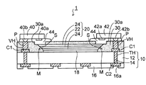
【解決手段】配線基板10と、配線基板10の上に接着され、両端に光路変換傾斜面Sを備えた光導波路20と、光導波路20の光路変換傾斜面Sに接して形成され、光反射性樹脂層30x又は金属ペースト層32から形成された光路変換ミラーMとを含む。光反射性樹脂層30xを光路変換ミラーMとして使用する場合は、光反射性樹脂層30xが光路変換傾斜面Sの側方のみに部分的に形成されていてもよいし、あるいは、配線基板10の全体に光導波路20を被覆して形成されていてもよい。
【選択図】図7
Description
図1〜図3は本発明の第1実施形態の光導波路装置の製造方法を示す断面図である。
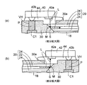
図5及び図6は本発明の第2実施形態の光導波路装置の製造方法を示す断面図である。
図9及び図10は本発明の第3実施形態の光導波路装置の製造方法を示す断面図である。第3実施形態の特徴は、光反射性樹脂層を光路変換ミラーとして利用するばかりではなく、光導波路を配線基板に接着する接着剤として兼用することにある。
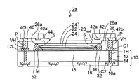
図11及び図12は本発明の第4実施形態の光導波路装置の製造方法を示す断面図である。第4実施形態の特徴は、金属ペースト層を光路変換ミラーとして利用するばかりではなく、光導波路を配線基板に接着する接着剤として兼用することにある。第4実施形態では、第1実施形態と同一工程及び同一要素には同一符号を付してその説明を省略する。
Claims (10)
- 配線基板と、
前記配線基板の上に接着され、両端に光路変換傾斜面を備えた光導波路と、
前記光導波路の前記光路変換傾斜面に接して形成され、光反射性樹脂層又は金属ペースト層から形成された光路変換ミラーとを有することを特徴とする光導波路装置。 - 前記光反射性樹脂層又は金属ペースト層は、前記光導波路の前記光路変換傾斜面の側方のみに部分的に形成されていることを特徴とする請求項1に記載の光導波路装置。
- 前記光反射性樹脂層又は金属ペースト層は前記光導波路の下側から前記光路変換傾斜面の側方に延在して形成されており、
前記光導波路は、前記光反射性樹脂層又は金属ペースト層によって前記配線基板に接着されていることを特徴とする請求項1に記載の光導波路装置。 - 前記配線基板及び前記光導波路の上に形成され、前記配線基板の両端側の接続パッドに到達するビアボールと、前記光路変換傾斜面の上に配置された光透過用開口部とが設けられた絶縁樹脂層と、
前記ビアホールに充填された電極パッドと、
前記光導波路の一端側の前記光路変換傾斜面に光結合され、前記配線基板の一端側の前記電極パッドに接続された発光素子と、
前記光導波路の他端側の前記光路変換傾斜面に光結合され、前記配線基板の他端側の前記電極パッドに接続された受光素子とをさらに有することを特徴とする請求項1に記載の光導波路装置。 - 前記光反射性樹脂層は白色樹脂からなることを特徴とする請求項1乃至4のいずれか一項に記載の光導波路装置。
- 配線基板の上に、両端に光路変換傾斜面を備える光導波路を接着する工程と、
前記光導波路の前記光路変換傾斜面に接するように光反射性樹脂層又は金属ペースト層を形成することにより光変換ミラーを得る工程とを有することを特徴とする光導波路装置の製造方法。 - 前記光反射性樹脂層又は金属ペースト層は、前記光導波路の前記光路変換傾斜面の側方のみに部分的に形成されることを特徴とする請求項6に記載の光導波路装置の製造方法。
- 両端に光路変換傾斜面を備える光導波路が接着される配線基板を用意し、前記配線基板の前記光導波路に対応する部分に光反射性樹脂材又は金属ペースト材を形成する工程と、
前記光導波路の前記光路変換傾斜面に前記光反射性樹脂材又は金属ペースト材が接するように、前記光導波路を前記光反射性樹脂材又は金属ペースト材に押し込む工程と、
前記光反射性樹脂材又は金属ペースト材を硬化させることにより、前記光導波路の前記光路変換傾斜面に接する光路変換ミラーを得ると共に、前記光導波路を前記配線基板に接着する工程とを有することを特徴とする光導波路装置の製造方法。 - 前記光路変換ミラーを得る工程の後に、
前記配線基板及び前記光導波路の上に、前記配線基板の両端側の接続パッドに到達するビアボールと、前記光路変換傾斜面上に配置された光透過用開口部とが設けられた絶縁樹脂層を形成する工程と、
前記ビアホール内に電解めっきにより電極パッドを充填する工程と、
前記光導波路の一端側の前記光路変換傾斜面に光結合される発光素子を前記配線基板の一端側の前記電極パッドに接続すると共に、前記光導波路の他端側の前記光路変換傾斜面に光結合される受光素子を前記配線基板の他端側の前記電極パッドに接続する工程とをさらに有することを特徴とする請求項7又は8に記載の光導波路装置の製造方法。 - 前記光反射性樹脂層は白色樹脂からなることを特徴とする請求項6乃至9のいずれか一項に記載の光導波路装置の製造方法。
Priority Applications (2)
| Application Number | Priority Date | Filing Date | Title |
|---|---|---|---|
| JP2009271837A JP5313849B2 (ja) | 2009-11-30 | 2009-11-30 | 光導波路装置及びその製造方法 |
| US12/946,198 US8903203B2 (en) | 2009-11-30 | 2010-11-15 | Optical waveguide device and method of manufacturing the same |
Applications Claiming Priority (1)
| Application Number | Priority Date | Filing Date | Title |
|---|---|---|---|
| JP2009271837A JP5313849B2 (ja) | 2009-11-30 | 2009-11-30 | 光導波路装置及びその製造方法 |
Publications (3)
| Publication Number | Publication Date |
|---|---|
| JP2011113039A true JP2011113039A (ja) | 2011-06-09 |
| JP2011113039A5 JP2011113039A5 (ja) | 2012-09-27 |
| JP5313849B2 JP5313849B2 (ja) | 2013-10-09 |
Family
ID=44068975
Family Applications (1)
| Application Number | Title | Priority Date | Filing Date |
|---|---|---|---|
| JP2009271837A Active JP5313849B2 (ja) | 2009-11-30 | 2009-11-30 | 光導波路装置及びその製造方法 |
Country Status (2)
| Country | Link |
|---|---|
| US (1) | US8903203B2 (ja) |
| JP (1) | JP5313849B2 (ja) |
Cited By (5)
| Publication number | Priority date | Publication date | Assignee | Title |
|---|---|---|---|---|
| JP2013003224A (ja) * | 2011-06-14 | 2013-01-07 | Shinko Electric Ind Co Ltd | 光導波路及びその製造方法と光導波路装置 |
| JP2013152287A (ja) * | 2012-01-24 | 2013-08-08 | Hitachi Cable Ltd | 光モジュール及びその製造方法 |
| JP2014089262A (ja) * | 2012-10-29 | 2014-05-15 | Shinko Electric Ind Co Ltd | 光導波路、光モジュール及び光導波路の製造方法 |
| KR101405611B1 (ko) | 2012-05-30 | 2014-06-10 | 엘지이노텍 주식회사 | 광 인쇄회로기판 및 이의 제조 방법 |
| JP2021515980A (ja) * | 2018-03-06 | 2021-06-24 | オスラム オーエルイーディー ゲゼルシャフト ミット ベシュレンクテル ハフツングOSRAM OLED GmbH | 半導体レーザー |
Families Citing this family (7)
| Publication number | Priority date | Publication date | Assignee | Title |
|---|---|---|---|---|
| JP5842714B2 (ja) * | 2012-03-30 | 2016-01-13 | 富士通株式会社 | 光導波路デバイス、および、光導波路デバイスの製造方法 |
| US8895429B2 (en) * | 2013-03-05 | 2014-11-25 | Eastman Kodak Company | Micro-channel structure with variable depths |
| JP6235878B2 (ja) * | 2013-11-25 | 2017-11-22 | 新光電気工業株式会社 | 光導波路装置及びその製造方法 |
| JP6460515B2 (ja) * | 2014-10-24 | 2019-01-30 | 日東電工株式会社 | 光電気混載基板およびその製法 |
| US9721812B2 (en) * | 2015-11-20 | 2017-08-01 | International Business Machines Corporation | Optical device with precoated underfill |
| JP2018105925A (ja) * | 2016-12-22 | 2018-07-05 | ルネサスエレクトロニクス株式会社 | 半導体装置およびその製造方法 |
| US11675128B2 (en) * | 2021-02-18 | 2023-06-13 | Cisco Technology, Inc. | End-face coupling structures within electrical backend |
Citations (5)
| Publication number | Priority date | Publication date | Assignee | Title |
|---|---|---|---|---|
| JPH09214003A (ja) * | 1996-01-31 | 1997-08-15 | New Japan Radio Co Ltd | 光半導体装置及びその製造方法 |
| JP2007156026A (ja) * | 2005-12-02 | 2007-06-21 | Kyocera Corp | 光配線モジュール |
| JP2008033217A (ja) * | 2006-07-06 | 2008-02-14 | Kuraray Co Ltd | 反射型スクリーン及び前面投射型表示システム |
| JP2008299287A (ja) * | 2007-06-04 | 2008-12-11 | Fuji Xerox Co Ltd | 光電子回路基板およびその製造方法 |
| JP2009063766A (ja) * | 2007-09-05 | 2009-03-26 | Shinko Electric Ind Co Ltd | 光導波路の形成方法 |
Family Cites Families (14)
| Publication number | Priority date | Publication date | Assignee | Title |
|---|---|---|---|---|
| JP2002365457A (ja) | 2001-06-06 | 2002-12-18 | Sony Corp | 光導波路およびその製造方法、ならびに光信号伝送装置 |
| JP4079146B2 (ja) * | 2002-09-20 | 2008-04-23 | 凸版印刷株式会社 | 光導波路の製造方法 |
| US7091057B2 (en) * | 2003-12-19 | 2006-08-15 | Agency For Science, Technology And Research | Method of making a single-crystal-silicon 3D micromirror |
| JP4587772B2 (ja) * | 2004-10-22 | 2010-11-24 | イビデン株式会社 | 多層プリント配線板 |
| JP2006267346A (ja) * | 2005-03-23 | 2006-10-05 | Fuji Xerox Co Ltd | 光学部材の製造方法 |
| US8045829B2 (en) | 2005-12-02 | 2011-10-25 | Kyocera Corporation | Optical waveguide member, optical wiring board, optical wiring module and method for manufacturing optical waveguide member and optical wiring board |
| JP4538484B2 (ja) | 2006-10-24 | 2010-09-08 | 太陽インキ製造株式会社 | 光硬化性熱硬化性樹脂組成物およびそれを用いたプリント配線板 |
| JP4704322B2 (ja) * | 2006-11-30 | 2011-06-15 | 新光電気工業株式会社 | 光電気混載基板の製造方法 |
| EP2096473B1 (en) * | 2006-12-26 | 2012-08-08 | Mitsui Chemicals, Inc. | Optical / electrical hybrid circuit board and manufacturing method of the same |
| JP2008250007A (ja) | 2007-03-30 | 2008-10-16 | Fuji Xerox Co Ltd | 光電子回路基板 |
| JP2009175418A (ja) * | 2008-01-24 | 2009-08-06 | Shinko Electric Ind Co Ltd | 光電気混載基板及びその製造方法 |
| JP2010028006A (ja) * | 2008-07-24 | 2010-02-04 | Sony Corp | 光学装置 |
| JP2010139562A (ja) * | 2008-12-09 | 2010-06-24 | Shinko Electric Ind Co Ltd | 光導波路、光導波路搭載基板及び光送受信装置 |
| WO2010074186A1 (en) * | 2008-12-22 | 2010-07-01 | Panasonic Electric Works Co., Ltd. | Method for forming mirror-reflecting film in optical wiring board, and optical wiring board |
-
2009
- 2009-11-30 JP JP2009271837A patent/JP5313849B2/ja active Active
-
2010
- 2010-11-15 US US12/946,198 patent/US8903203B2/en active Active
Patent Citations (5)
| Publication number | Priority date | Publication date | Assignee | Title |
|---|---|---|---|---|
| JPH09214003A (ja) * | 1996-01-31 | 1997-08-15 | New Japan Radio Co Ltd | 光半導体装置及びその製造方法 |
| JP2007156026A (ja) * | 2005-12-02 | 2007-06-21 | Kyocera Corp | 光配線モジュール |
| JP2008033217A (ja) * | 2006-07-06 | 2008-02-14 | Kuraray Co Ltd | 反射型スクリーン及び前面投射型表示システム |
| JP2008299287A (ja) * | 2007-06-04 | 2008-12-11 | Fuji Xerox Co Ltd | 光電子回路基板およびその製造方法 |
| JP2009063766A (ja) * | 2007-09-05 | 2009-03-26 | Shinko Electric Ind Co Ltd | 光導波路の形成方法 |
Cited By (5)
| Publication number | Priority date | Publication date | Assignee | Title |
|---|---|---|---|---|
| JP2013003224A (ja) * | 2011-06-14 | 2013-01-07 | Shinko Electric Ind Co Ltd | 光導波路及びその製造方法と光導波路装置 |
| JP2013152287A (ja) * | 2012-01-24 | 2013-08-08 | Hitachi Cable Ltd | 光モジュール及びその製造方法 |
| KR101405611B1 (ko) | 2012-05-30 | 2014-06-10 | 엘지이노텍 주식회사 | 광 인쇄회로기판 및 이의 제조 방법 |
| JP2014089262A (ja) * | 2012-10-29 | 2014-05-15 | Shinko Electric Ind Co Ltd | 光導波路、光モジュール及び光導波路の製造方法 |
| JP2021515980A (ja) * | 2018-03-06 | 2021-06-24 | オスラム オーエルイーディー ゲゼルシャフト ミット ベシュレンクテル ハフツングOSRAM OLED GmbH | 半導体レーザー |
Also Published As
| Publication number | Publication date |
|---|---|
| US20110129182A1 (en) | 2011-06-02 |
| US8903203B2 (en) | 2014-12-02 |
| JP5313849B2 (ja) | 2013-10-09 |
Similar Documents
| Publication | Publication Date | Title |
|---|---|---|
| JP5313849B2 (ja) | 光導波路装置及びその製造方法 | |
| KR100720854B1 (ko) | 광·전기배선기판, 실장기판 및 광전기배선기판의 제조방법 | |
| US8041159B2 (en) | Optical/electrical hybrid substrate and method of manufacturing the same | |
| JP5670169B2 (ja) | 光導波路の製造方法 | |
| TW200404487A (en) | A light reception/emission device built-in module with optical and electrical wiring combined therein and method of making the same | |
| WO2013179522A1 (ja) | 光電気混載フレキシブルプリント配線板の製造方法、及び光電気混載フレキシブルプリント配線板 | |
| JP5395734B2 (ja) | 光電気複合基板の製造方法 | |
| US8737781B2 (en) | Optical waveguide and method of manufacturing the same, and optical waveguide device | |
| JP6286853B2 (ja) | 電子装置とその製造方法、及び電子機器 | |
| JP6084027B2 (ja) | 光導波路装置及びその製造方法 | |
| JP4690870B2 (ja) | 光電気集積配線基板及び光電気集積配線システム | |
| JP4624162B2 (ja) | 光電気配線基板 | |
| JP4227471B2 (ja) | 受発光素子内蔵光電気混載配線モジュールの製造方法 | |
| JP5137393B2 (ja) | 光結合器 | |
| JP5409441B2 (ja) | 光伝送基板および光モジュール | |
| JP2007094296A (ja) | 光導波路デバイス及び光導波路デバイスの製造方法 | |
| JP5976769B2 (ja) | 光導波路及び光導波路装置 | |
| JP2012088634A (ja) | 光導波路デバイス及びその製造方法 | |
| JP5136142B2 (ja) | 光基板の製造方法 | |
| JP2007086367A (ja) | 光ピン、光ピンコネクタ及び光路変換用モジュール | |
| JP2005345928A (ja) | 光導波路デバイス及びその製造方法、光路変換部品、光路変換部品付きの光導波路構造体 | |
| JP6084024B2 (ja) | 光導波路装置及びその製造方法 | |
| JP4698728B2 (ja) | 光電気集積配線基板および光電気集積配線システム | |
| JP5312311B2 (ja) | 光伝送基板および光モジュール | |
| JP4194515B2 (ja) | 二次元光導波装置、及びそれを用いた光電融合配線基板 |
Legal Events
| Date | Code | Title | Description |
|---|---|---|---|
| A521 | Written amendment |
Free format text: JAPANESE INTERMEDIATE CODE: A523 Effective date: 20120809 |
|
| A621 | Written request for application examination |
Free format text: JAPANESE INTERMEDIATE CODE: A621 Effective date: 20120809 |
|
| A131 | Notification of reasons for refusal |
Free format text: JAPANESE INTERMEDIATE CODE: A131 Effective date: 20130219 |
|
| A977 | Report on retrieval |
Free format text: JAPANESE INTERMEDIATE CODE: A971007 Effective date: 20130220 |
|
| A521 | Written amendment |
Free format text: JAPANESE INTERMEDIATE CODE: A523 Effective date: 20130327 |
|
| TRDD | Decision of grant or rejection written | ||
| A01 | Written decision to grant a patent or to grant a registration (utility model) |
Free format text: JAPANESE INTERMEDIATE CODE: A01 Effective date: 20130625 |
|
| A61 | First payment of annual fees (during grant procedure) |
Free format text: JAPANESE INTERMEDIATE CODE: A61 Effective date: 20130704 |
|
| R150 | Certificate of patent or registration of utility model |
Free format text: JAPANESE INTERMEDIATE CODE: R150 Ref document number: 5313849 Country of ref document: JP Free format text: JAPANESE INTERMEDIATE CODE: R150 |


