JP2006075418A - Token selecting device - Google Patents
Token selecting device Download PDFInfo
- Publication number
- JP2006075418A JP2006075418A JP2004264067A JP2004264067A JP2006075418A JP 2006075418 A JP2006075418 A JP 2006075418A JP 2004264067 A JP2004264067 A JP 2004264067A JP 2004264067 A JP2004264067 A JP 2004264067A JP 2006075418 A JP2006075418 A JP 2006075418A
- Authority
- JP
- Japan
- Prior art keywords
- light
- medal
- emitting element
- passage
- tokens
- Prior art date
- Legal status (The legal status is an assumption and is not a legal conclusion. Google has not performed a legal analysis and makes no representation as to the accuracy of the status listed.)
- Pending
Links
- 230000003287 optical effect Effects 0.000 claims abstract description 17
- 238000001514 detection method Methods 0.000 claims abstract description 16
- 238000007599 discharging Methods 0.000 claims description 3
- 230000005540 biological transmission Effects 0.000 description 7
- 230000001360 synchronised effect Effects 0.000 description 7
- 230000002159 abnormal effect Effects 0.000 description 5
- 238000000034 method Methods 0.000 description 5
- 239000004973 liquid crystal related substance Substances 0.000 description 4
- 230000007717 exclusion Effects 0.000 description 3
- ORQBXQOJMQIAOY-UHFFFAOYSA-N nobelium Chemical compound [No] ORQBXQOJMQIAOY-UHFFFAOYSA-N 0.000 description 3
- 241000287127 Passeridae Species 0.000 description 2
- 238000010586 diagram Methods 0.000 description 2
- 230000001681 protective effect Effects 0.000 description 2
- 101100153168 Arabidopsis thaliana TIC21 gene Proteins 0.000 description 1
- 101100273813 Homo sapiens CDKN1A gene Proteins 0.000 description 1
- 108700038981 SUMO-1 Proteins 0.000 description 1
- 101100083338 Saccharomyces cerevisiae (strain ATCC 204508 / S288c) PIC2 gene Proteins 0.000 description 1
- 101100083337 Schizosaccharomyces pombe (strain 972 / ATCC 24843) pic1 gene Proteins 0.000 description 1
- 102100026940 Small ubiquitin-related modifier 1 Human genes 0.000 description 1
- 230000004397 blinking Effects 0.000 description 1
- 230000002950 deficient Effects 0.000 description 1
- 230000000694 effects Effects 0.000 description 1
- 238000003780 insertion Methods 0.000 description 1
- 230000037431 insertion Effects 0.000 description 1
- 230000001788 irregular Effects 0.000 description 1
- 230000007257 malfunction Effects 0.000 description 1
- 238000000691 measurement method Methods 0.000 description 1
- 230000035945 sensitivity Effects 0.000 description 1
- 230000000087 stabilizing effect Effects 0.000 description 1
- 238000005728 strengthening Methods 0.000 description 1
Images
Landscapes
- Slot Machines And Peripheral Devices (AREA)
Abstract
Description
本発明は、雀球やパチンコスロット、スロットマシン等の遊技機、あるいは、自動販売機のように、メダル(トークン等の遊技媒体を含む)やコイン(メダルと総称する)を使用する機器(遊技機等と総称する)に用いられるメダル選別装置に関する。 The present invention relates to devices (games) that use medals (including game media such as tokens) and coins (generally referred to as medals) such as game machines such as sparrow balls, pachinko slots, slot machines, or vending machines. The present invention relates to a medal sorting device used in general.
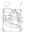
雀球やパチンコスロット、スロットマシン等の遊技機には、図1に示す如く、メダル投入口22から遊技機筐体20内に投入されたメダル12のうち、厚みや重さや外周のギザギザの有無等に基づいて不良メダルを選別したり、投入枚数を計数して法定枚数に達したことを検知するためのメダル選別装置(メダルセレクタとも称する)30が備えられている(特許文献1参照)。
As shown in FIG. 1, a gaming machine such as a sparrow ball, a pachinko slot, or a slot machine has a thickness, a weight, or a jagged outer periphery of the
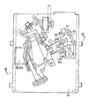
そして、図2に示す如く、該メダルセレクタ30により選別され、受入を拒否された、メダル通路24中のメダル12を、メダル通路外の排出通路26に排出するためのメダルキャンセル装置が設けられている(特許文献2参照)。
As shown in FIG. 2, there is provided a medal canceling device for discharging the
前記メダルセレクタ30のベース(セレクタベースと称する)32は、図2中に示されない遊技機筐体に固定されている。該セレクタベース32にねじ止めされたメダルレール34とメダルシュート36により、図3に示すメダル通路24が形成されている。該メダルシュート36の一部には、図3に示す如く、キャンセルメダル排出通路26の入口となる、メダル排出用の切り欠き36aが設けられている。
A base 32 (referred to as a selector base) 32 of the
前記セレクタベース32の上部には、メダル通路24中のメダル12を側面から押して排出するための、メダルキャンセル装置40のキャンセルプレート44の上部を回動自在に支持するキャンセルプレート支点軸45が配設されている。該キャンセルプレート44は、その上方に位置する前記支点軸45を中心に、ばね46で付勢されつつ、揺動自在に支持されており、図4に示す如く、キャンセル軸42により押され、ばね46に抗してメダル通路24中に下端44aが進入した時に、その中のメダル12を側面から押して、メダルシュート36の切り欠き36aから排出通路26に排出する。
A cancel
前記セレクタベース32には、更に、メダル通路24中のメダル12の姿勢を安定させるためのプッシャー37を回動自在に支持するプッシャー支点軸38が配設されている。該プッシャー37は、図4に示す如く、ばね39で付勢されつつ、その上方に位置する前記プッシャー支点軸38を中心に回動して、メダル通路24中のメダル12の姿勢を安定させる。
The
前記セレクタベース32には、更に、メダル通路24からメダル12を排除するための排除レバー50を配置したソレノイドブラケット55がねじ止めされている。該ソレノイドブラケット55には、例えばフラッパー式のソレノイド54が固定されている。
Further, the
前記排除レバー50は、メダル受入時はソレノイド54により吸引され、メダル通路24を遮らず、逆にメダル非受入時は、弾性体により引かれて、メダル通路24を遮るようにされている。
The exclusion lever 50 is attracted by the solenoid 54 when the medal is received and does not block the
前記セレクタベース32のメダル通過部には、更に、メダル12の通過枚数を計数するための、例えば光透過型のメダルセンサ58が配設されている。
The medal passage portion of the
遊技機等に用いられるメダル選別装置としては、特許文献3や特許文献4に記載されているような機構を用いて、不正操作の防止を図ると共に、メダルを選別する装置が知られている。
As a medal sorting device used in a gaming machine or the like, there is known a device that uses a mechanism as described in
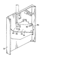
特許文献3に示されたメダル選別装置においては、図5(正面図)、図6(背面図)及び図7(斜視図)に示す如く、メダル通路24の入口側に、図8に詳細に示す如く、軸受60、61に支持された軸62を中心に回動する第1突起部材64と、その上端65及び下端66が、メダル12の通過により、図9に示す如く、ばね68に抗してメダル通路24の窓25から出没したとき、その動きを検出する、例えば透過型の光センサでなる第1検出器70を設けており、この第1検出器70が出力する出力信号の変化から異常状態を検出することができる。
In the medal sorting device disclosed in
即ち、前記第1検出器70は、図8に詳細に示した如く、発光素子71と受光素子72とをある間隔を持たせて配置し、両素子の間を第1突起部材64の後端部67が横切るようにされている。従って、メダル通路24において、メダル詰まり等が生じた場合や不正操作が行なわれると、第1突起部材64の上端65及び下端66が押される時間が長くなり、検出信号の立上りから立下りまでの時間が所定時間より長くなるので、異常状態を検出することができる。これにより、図10に例示するようなセル板100と呼ばれる板状の道具をメダル通路24に挿入して不正に遊技する行為が防止できる。即ち、メダル12が通過する場合は、第1検出器70の受光素子72の出力が、メダル12の通過により第1突起部材64が押された一瞬だけオフになるのに対して、セル板100が挿入された場合は、第1検出器70の受光素子72の出力がオフのままとなる。
That is, as shown in detail in FIG. 8, the
更に、第2検出器として、複数の光センサ80、84をメダル通路24の出口近傍に順次配置した場合には、図11に例示するように、入側センサ80を通った後、所定時間内に出側センサ84を通る正常なメダルの数を計数することができ、各センサ80、84のオンオフの順序や時間変化により、異常動作を検出できる。例えば入側センサ80がオンとなる前に出側センサ84がオンとなったり、入側センサ80がオンした後、所定時間経過しても、出側センサ84がオンオフしなかったり、入側センサ80がオフした後、所定時間経過しても出側センサ84がオフにならない時を異常動作とすることにより、糸吊りメダル等を使用した不正行為も防止できる。即ち、糸吊りメダルを戻す動作では、正常な投入動作とは逆に、出側センサ84の出力が変化してから入側センサ80の出力が変化する。
Further, when a plurality of
前記第2検出器のセンサ内部は、図12に示すような反射型フォトインタラプタや、図13に示すような透過型フォトインタラプタを2列に並べたものが使われている。 Inside the sensor of the second detector, a reflection type photo interrupter as shown in FIG. 12 or a transmission type photo interrupter as shown in FIG. 13 arranged in two rows is used.
前記反射型フォトインタラプタは、図12に示した如く、メダル12の通過時にメダルの側面に発光素子(例えばLED)81、85により光を当て、メダル12からの反射を受光素子(例えばフォトトランジスタやフォトIC)82、86により受光して、メダル12の検出を行なっている。
As shown in FIG. 12, the reflection type photo interrupter illuminates the side of the
又、前記透過型フォトインタラプタは、図13に示した如く、メダル経路にまたがるように発光素子81、85と受光素子82、86を配置させ、メダル未通過時に発光素子81、85の光を常時受光素子82、86に入光させておき、メダル通過時にメダルが、この光軸を遮ることにより、受光素子82、86への入光が遮断されることで、メダル通過を検知する。
Further, as shown in FIG. 13, the transmissive photo interrupter has
しかしながら、上記メダルセレクタ30においては、メダル12の通過を検出する検出手段として、第1の検出器70及び第2の検出器80、84の2組の検出器を設ける必要があり、メダル12の通過の不正を検出する制御が複雑になるだけでなく、制御の誤動作も多く、又、高価であった。
However, in the
又、図10に示したセル板100をメダル通路24に挿入して不正に遊技する行為が行われた場合、図10に破線で示す如く、第1検出器70の突起部65、66と対応する位置に窓101を設けて、該突起部をくぐり抜け、第2検出器80、84までセル板100を挿入すると共に、セル板を更に1枚追加し、第1検出器70の突起部65、66をオンオフ動作させることにより、不正行為を行うことが考えられる。即ち、メダル通路24の出口の近傍に第2検出器として2個の光センサ80、84がメダル移動方向に互いに近接して配置されている場合、1個目の入側センサ80は2個目の出側センサ84よりもメダル12が先に通過する位置にあるため、セル板100の先端部に、これらの2個の光センサ80、84の配列の通りにLED等の発光素子102、104を配置し、例えばIC10bにより、図14に示す如く、メダル通過と同等の規則的なタイミンクで点滅させることにより、第2検出器80、84にメダル12が通過したのと同等な光を入力させ、あたかもメダル12が通過したと同等の出力信号を出させることができてしまう。
In addition, when an illegal act of inserting the
本発明は、前記従来の問題点を解決するべくなされたもので、比較的単純な構成により、セル板等を用いた不正操作を確実に防止することを課題とする。 The present invention has been made to solve the above-described conventional problems, and an object thereof is to reliably prevent unauthorized operation using a cell plate or the like with a relatively simple configuration.
本発明は、投入されたメダルの中から適正なメダルを選別し、不適正なメダルを排出するための、メダル通路の出口近傍にメダルの移動方向に複数のメダル検出手段が配設されたメダル選別装置において、少なくとも1つのメダル検出手段を、光変調した光を発生する発光素子と、該発光素子が発生した光変調された光に同期して光を検知する受光素子とを組み合わせた、透過型の光センサとすることにより、前記課題を解決したものである。 In the present invention, a medal in which a plurality of medal detection means are arranged in the medal movement direction in the vicinity of the exit of the medal passage for selecting an appropriate medal from among inserted medals and discharging the improper medal. In the sorting apparatus, at least one medal detection means is a transmission that combines a light emitting element that generates light modulated light and a light receiving element that detects light in synchronization with the light modulated light generated by the light emitting element. The above-described problems are solved by using a type of optical sensor.
本発明によれば、第1検出器を削除できるので安価である。又、メダル経路を利用した、セル板等による外乱光不正ができなくなる。更に、発光素子の代わりに液晶シャッタを設けたセル板による不正を防止することも可能である。 According to the present invention, the first detector can be eliminated, so that it is inexpensive. In addition, disturbance light fraud due to a cell plate or the like using a medal path cannot be performed. Further, it is possible to prevent fraud due to a cell plate provided with a liquid crystal shutter instead of the light emitting element.
以下図面を参照して、本発明の実施形態を詳細に説明する。 Hereinafter, embodiments of the present invention will be described in detail with reference to the drawings.
本実施形態は、各光センサ80、84のオンオフの順序や時間変化により異常動作を検出できるので、糸吊りコイン等を使用した不正行為も防止できる、複数の光センサ80、84をメダル通路24の出口近傍に順次配設した第2検出器について行なったものである。
In this embodiment, since the abnormal operation can be detected by the order of turning on and off the
即ち、少なくとも2組ある光センサのうち少なくとも1個(ここでは入側の光センサ80)を、図15(A)に示す如く、光変調した光を発生する発光素子(例えば発光ダイオード)81と、該発光素子81が発生した光変調した光に同期して光を検知する受光素子(例えばフォトダイオード)82とを組み合わせた、光変調式で且つ同期式の透過型の光センサとする。ここで、光変調式は、規則性を有しパルス状の光を発生する駆動方式である。又、同期式は、発光素子81が発光した光変調された光に同期して受光素子82が受光する計測方式である。つまり、光変調式で且つ同期式の場合、図15(A)に示したようにメダル12により光が遮断されると受光素子82は光変調駆動タイミングと同期して検知信号を出力する。しかし、図15(B)に示すしたように、セル板100により光が遮断されセル板100に搭載された発光素子102等の駆動タイミングによる外乱光は光変調駆動タイミングと非同期のため外乱光による検知信号は出力されない。
That is, at least one of the at least two sets of photosensors (here, the input side photosensor 80) is connected to a light emitting element (for example, a light emitting diode) 81 that generates light modulated light as shown in FIG. A light-modulating and synchronous transmission-type optical sensor is combined with a light-receiving element (for example, a photodiode) 82 that detects light in synchronization with the light-modulated light generated by the light-emitting
第2検出器の駆動回路を図16に示す。図において、PICは、フォトICであり、本実施形態では、第2検出器の入側の光センサ80のPIC1を光変調式同期型として、その変調部90により発光素子81をパルス駆動することにより光変調された光を発生させ、又、同時にフォトIC内の受光素子82かの出力らの信号を増幅する増幅器94を同期させメダル12の検出準備をする。一方、出側の光センサ84のPIC2は非同期型としている。CN1端子のS1、S2は第2検出器の光センサ80、84の検知出力(遮光はHi、入光はLow)である。
A driving circuit for the second detector is shown in FIG. In the figure, PIC is a photo IC. In this embodiment, the PIC1 of the photosensor 80 on the input side of the second detector is a light modulation type synchronous type, and the
これにより、外から別体で入ってきた光(セル板100に取り付いて第2検出器の位置まで入ってきたLED等の発光素子102、104)により受光素子82を反応させることができなくなる。何故なら、発光素子102の駆動タイミングが、受光素子82の受光可能な検出タイミングと合わないと、増幅器94が反応しないため、メダル検知と認識することができないようになるからである。つまり、発光素子駆動タイミングで検知出力が不規則になる。
This makes it impossible for the
即ち、透過型の場合、発光を、受光できるタイミングと、同期させたものを、1対とする光センサを使用した場合、直接受光素子を動作させるためには、図15(A)に示したように、受光素子82が受光可能なように、同期させた光を、受光素子82に直接当てると受光素子82の反応を起こすことができるが、図15(B)に示すように、セル板100に搭載された発光素子102により、受光素子82で受光可能に、同期させた光を安定して作成することは困難である。なお、たまたま同期がとれる場合もあるので、不正操作検出アルゴリズムを強化(センサ80とセンサ84の出力タイミングのずれ検出等)することにより不正操作に対する安全性を更に高めることもできる。
That is, in the case of the transmission type, when using a pair of optical sensors that synchronize with the timing at which light emission can be received, in order to directly operate the light receiving element, as shown in FIG. In this way, when the synchronized light is directly applied to the
本実施形態においては、入側センサ80のみを光変調した光としているので構成が簡略である。なお、出側センサ84にも光変調を用いることもできる。
In this embodiment, since only the
また、メダル通路24の内部の隙間で反対側の発光素子81、85からの光を遮光、透光を行なう方法として、光センサ80、84の2光軸と同じ位置に、液晶による光のシャッタを2個配置し、電気信号で開閉することにより、裏面からの光のみ遮光、透光を行なうことも考えられる。しかし、液晶シャッタには保護膜があるため、この保護膜を検出できる程度に発光側の光量を下げて感度を高めることにより、液晶シャッタによる不正操作も防止することもできる。
Further, as a method of shielding and transmitting light from the
なお、前記説明においては、第2検出器が2個とされ、共に透過型とされていたが、第2検出器の数は2個に限定されず、3個以上であってもよい。又、第2検出器のいずれか1つを透過型の同期、同調方式とし、その他を反射型としてもよい。発光素子と受光素子も発光ダイオードとフォトダイオードに限定されない。 In the above description, the number of second detectors is two, and both are transmissive. However, the number of second detectors is not limited to two and may be three or more. Further, any one of the second detectors may be a transmission type synchronization and tuning method, and the other may be a reflection type. The light emitting element and the light receiving element are not limited to the light emitting diode and the photodiode.
12…メダル
24…メダル通路
30…メダルセレクタ
80、84…第2検出器(光センサ)
81、85…発光素子(発光ダイオード)
82、86…受光素子(フォトダイオード)
90…変調部
12 ...
81, 85 ... Light emitting element (light emitting diode)
82, 86 ... Light receiving element (photodiode)
90 ... modulation section
Claims (1)
少なくとも1つのメダル検出手段を、光変調した光を発生する発光素子と、該発光素子が発生した光変調した光に同期して光を検知する受光素子とを組み合わせた、透過型の光センサとしたことを特徴とするメダル選別装置。 In the medal sorting device in which a plurality of medal detection means are arranged in the movement direction of the medal in the vicinity of the exit of the medal passage for selecting an appropriate medal from the inserted medals and discharging the improper medal.
A transmissive optical sensor comprising a combination of a light emitting element that generates light modulated light and a light receiving element that detects light in synchronization with the light modulated light generated by the light emitting element; A medal sorting device characterized by that.
Priority Applications (1)
| Application Number | Priority Date | Filing Date | Title |
|---|---|---|---|
| JP2004264067A JP2006075418A (en) | 2004-09-10 | 2004-09-10 | Token selecting device |
Applications Claiming Priority (1)
| Application Number | Priority Date | Filing Date | Title |
|---|---|---|---|
| JP2004264067A JP2006075418A (en) | 2004-09-10 | 2004-09-10 | Token selecting device |
Publications (1)
| Publication Number | Publication Date |
|---|---|
| JP2006075418A true JP2006075418A (en) | 2006-03-23 |
Family
ID=36155353
Family Applications (1)
| Application Number | Title | Priority Date | Filing Date |
|---|---|---|---|
| JP2004264067A Pending JP2006075418A (en) | 2004-09-10 | 2004-09-10 | Token selecting device |
Country Status (1)
| Country | Link |
|---|---|
| JP (1) | JP2006075418A (en) |
Cited By (2)
| Publication number | Priority date | Publication date | Assignee | Title |
|---|---|---|---|---|
| JP2007296026A (en) * | 2006-04-28 | 2007-11-15 | Sanyo Product Co Ltd | Game machine using token and token detection |
| JP2012024610A (en) * | 2011-10-05 | 2012-02-09 | Sanyo Product Co Ltd | Game machine using token and token detection |
Citations (5)
| Publication number | Priority date | Publication date | Assignee | Title |
|---|---|---|---|---|
| JPH09215815A (en) * | 1996-02-13 | 1997-08-19 | Samii Kk | Method for detecting winning ball and game ball detecting device |
| JP2003275382A (en) * | 2002-03-26 | 2003-09-30 | Omron Corp | Thrown-in medal detecting device, and thrown-in medal selecting device for game machine |
| JP2006034944A (en) * | 2004-03-05 | 2006-02-09 | Aruze Corp | Game machine and token selector |
| JP2006055181A (en) * | 2004-08-17 | 2006-03-02 | Omron Corp | Fed token sorting device for game machine |
| JP2006061338A (en) * | 2004-08-26 | 2006-03-09 | Heiwa Corp | Game machine |
-
2004
- 2004-09-10 JP JP2004264067A patent/JP2006075418A/en active Pending
Patent Citations (5)
| Publication number | Priority date | Publication date | Assignee | Title |
|---|---|---|---|---|
| JPH09215815A (en) * | 1996-02-13 | 1997-08-19 | Samii Kk | Method for detecting winning ball and game ball detecting device |
| JP2003275382A (en) * | 2002-03-26 | 2003-09-30 | Omron Corp | Thrown-in medal detecting device, and thrown-in medal selecting device for game machine |
| JP2006034944A (en) * | 2004-03-05 | 2006-02-09 | Aruze Corp | Game machine and token selector |
| JP2006055181A (en) * | 2004-08-17 | 2006-03-02 | Omron Corp | Fed token sorting device for game machine |
| JP2006061338A (en) * | 2004-08-26 | 2006-03-09 | Heiwa Corp | Game machine |
Cited By (2)
| Publication number | Priority date | Publication date | Assignee | Title |
|---|---|---|---|---|
| JP2007296026A (en) * | 2006-04-28 | 2007-11-15 | Sanyo Product Co Ltd | Game machine using token and token detection |
| JP2012024610A (en) * | 2011-10-05 | 2012-02-09 | Sanyo Product Co Ltd | Game machine using token and token detection |
Similar Documents
| Publication | Publication Date | Title |
|---|---|---|
| JP2006072687A (en) | Deposited coin detection method and device, and game machine | |
| JP2006075418A (en) | Token selecting device | |
| JP2006271865A (en) | Game machine and token selector | |
| JP4864386B2 (en) | Game machine | |
| JP2008000498A (en) | Token sorter | |
| JP4629384B2 (en) | Game machine | |
| JP4784061B2 (en) | Game machine | |
| JP2006330888A (en) | Coin selector | |
| JP4224003B2 (en) | Game machine | |
| JP5055819B2 (en) | Game medium detection device | |
| JP2006136410A (en) | Token sorting device | |
| US20070007723A1 (en) | Gaming machine and coin selection device | |
| JP4742532B2 (en) | Game machine input medal sorting device | |
| JP4323356B2 (en) | Gaming machine medal selector and gaming machine equipped with this medal selector | |
| JP2006251954A (en) | Bill insertion sensor device of bill identifying device | |
| JP4293544B2 (en) | Gaming machine medal selector and gaming machine equipped with this medal selector | |
| JP2005312818A (en) | Judgment method of token sorting device | |
| JP2005279059A (en) | Slot machine | |
| JP2006034944A (en) | Game machine and token selector | |
| JP4505592B2 (en) | Fraud prevention device for coin detection device of coin selector | |
| JP2005312806A (en) | Token sorting device of slot machine | |
| JP2006034998A (en) | Game machine | |
| JP4342384B2 (en) | Game machine | |
| JP2006055181A (en) | Fed token sorting device for game machine | |
| JP2005279246A (en) | Game machine |
Legal Events
| Date | Code | Title | Description |
|---|---|---|---|
| A621 | Written request for application examination |
Free format text: JAPANESE INTERMEDIATE CODE: A621 Effective date: 20070906 |
|
| A131 | Notification of reasons for refusal |
Free format text: JAPANESE INTERMEDIATE CODE: A131 Effective date: 20100525 |
|
| A02 | Decision of refusal |
Free format text: JAPANESE INTERMEDIATE CODE: A02 Effective date: 20100928 |


