JP2004159067A - Vertical sharpness device and tv receiver provided with same - Google Patents
Vertical sharpness device and tv receiver provided with same Download PDFInfo
- Publication number
- JP2004159067A JP2004159067A JP2002322498A JP2002322498A JP2004159067A JP 2004159067 A JP2004159067 A JP 2004159067A JP 2002322498 A JP2002322498 A JP 2002322498A JP 2002322498 A JP2002322498 A JP 2002322498A JP 2004159067 A JP2004159067 A JP 2004159067A
- Authority
- JP
- Japan
- Prior art keywords
- signal
- vertical sharpness
- delay line
- circuit
- sharpness
- Prior art date
- Legal status (The legal status is an assumption and is not a legal conclusion. Google has not performed a legal analysis and makes no representation as to the accuracy of the status listed.)
- Pending
Links
Images
Classifications
-
- H—ELECTRICITY
- H04—ELECTRIC COMMUNICATION TECHNIQUE
- H04N—PICTORIAL COMMUNICATION, e.g. TELEVISION
- H04N5/00—Details of television systems
- H04N5/14—Picture signal circuitry for video frequency region
- H04N5/20—Circuitry for controlling amplitude response
- H04N5/205—Circuitry for controlling amplitude response for correcting amplitude versus frequency characteristic
- H04N5/208—Circuitry for controlling amplitude response for correcting amplitude versus frequency characteristic for compensating for attenuation of high frequency components, e.g. crispening, aperture distortion correction
-
- H—ELECTRICITY
- H04—ELECTRIC COMMUNICATION TECHNIQUE
- H04N—PICTORIAL COMMUNICATION, e.g. TELEVISION
- H04N9/00—Details of colour television systems
- H04N9/64—Circuits for processing colour signals
- H04N9/646—Circuits for processing colour signals for image enhancement, e.g. vertical detail restoration, cross-colour elimination, contour correction, chrominance trapping filters
-
- H—ELECTRICITY
- H04—ELECTRIC COMMUNICATION TECHNIQUE
- H04N—PICTORIAL COMMUNICATION, e.g. TELEVISION
- H04N5/00—Details of television systems
- H04N5/14—Picture signal circuitry for video frequency region
- H04N5/142—Edging; Contouring
Landscapes
- Engineering & Computer Science (AREA)
- Multimedia (AREA)
- Signal Processing (AREA)
- Picture Signal Circuits (AREA)
- Processing Of Color Television Signals (AREA)
Abstract
Description
【0001】
【発明の属する技術分野】
本発明は、ビデオ信号(輝度信号)にTV(テレビジョン)画面の垂直方向のシャープネスを行う垂直シャープネス装置及びそれを備えたTV受像機に関するもので、特にTV受像機の視聴者の希望に応じて最適な垂直方向のシャープネスを行うことができる垂直シャープネス装置及びそれを備えたTV受像機に関する。
【0002】
【従来の技術】
従来より、TV受像機が有する機能としてシャープネス機能が知られている。このシャープネス機能は、画像の水平方向の輪郭を強調するものであり、対象物の輪郭を強調すると、その対象物が際立って見える。視聴者には、輪郭を強調しない場合に比べて対象物がくっきりと鮮明に見える。また、TV受像機では係るシャープネスに加えて、次のような項目の調整が可能である。
Brightness (ブライト) 明るさの調整
Contrast (コントラスト)白と黒の明るさの違い
Color (カラー) 色の濃さの調整
Tint (ティント) 色合いの調整
これらの項目について、TV受像機の視聴者は、希望の値に調整できるものが一般的である。これらの調整は、TV受像機本体につまみが存在して調整する場合と、リモートコントロールによりTV画面上に調整値を表示して調整する場合とがある。
【0003】
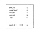
リモートコントロールによりTV画面上に調整値を表示するものとしては例えば、図2に示すような表示が行われる。図2では上からBrightness, Contrast, Sharp, Color, Tintの5つの項目について表示されている。このTV受像機では、Brightness, Contrast, Sharp, Color, Tintの5つの項目が視聴者の希望の値に調整できるという意味である。
【0004】
そして、現在調整中なのがBrightnessであり、その度合いは32である。視聴者はこのBrightness32を例えば0から63までの範囲で任意の値に設定できる。従って、視聴者は、上記5つの項目について自分の好みや受信状況(電界強度など)に応じて最適な値を選ぶことができる。
【0005】
なお、TV受像機のシャープネス機能については、例えば以下の特許文献1に記載されている。
【0006】
【特許文献1】
特開平10−93842号公報
【0007】
【発明が解決しようとする課題】
しかしながら、従来のTV受像機では画像の垂直方向の輪郭を強調する垂直シャープネスを視聴者が選択することはできなかった。垂直シャープネスは、1H(Hは1水平期間)期間前後のビデオ信号において、白から黒、又は黒から白に明るさが変化した場合にその変化を強調させて垂直方向の輪郭を強調するものである。この場合も輪郭を強調しない場合に比べて対象物がくっきりと見える効果がある。
【0008】
垂直シャープネスは、対象物がくっきりと見える効果がある一方で画面のノイズを増加させるというマイナス効果もある。このため、弱電界の地域などで垂直シャープネスを行うと、画面のノイズが激しくなり逆効果になってしまう。
【0009】
【課題を解決するための手段】
本発明は上述した従来技術の課題に鑑みなされたものであり、TV受像機の視聴者による垂直シャープネス制御信号が印加される端子と、該端子からの垂直シャープネス制御信号が印加される制御回路と、該制御回路からの垂直シャープネス制御信号に応じてビデオ信号の垂直シャープネスの度合いを調整する垂直シャープネス回路とを備えることを特徴とする。
【0010】
【発明の実施の形態】
次に、本発明の実施の形態について図面を参照しながら説明する。図1は、本発明の実施形態に係る垂直シャープネス装置のブロック図である。図において、1はTV受像機の視聴者による垂直シャープネス制御信号が印加される端子、2は該端子1からの垂直シャープネス制御信号が印加される制御回路としてのマイクロコンピュータ、3はビデオ信号が印加されるビデオ入力端子である。
【0011】
また、4は垂直シャープネス回路であって、前記ビデオ信号を1H(Hは1水平期間)期間遅延させる第1の1Hディレイライン5と、該第1の1Hディレイライン5の出力信号が印加される第2の1Hディレイライン6と、前記ビデオ信号と前記第2の1Hディレイライン6の出力信号とを加算する第1加算器7と、該第1加算器7の出力信号レベルを半分にする減衰回路8と、前記第1の1Hディレイライン5の出力信号と前記減衰回路8の出力信号とを減算する減算器9と、該減算器9の出力信号レベルを調整するレベル調整回路10と、該レベル調整回路10の出力信号と前記第1の1Hディレイライン5の出力信号とを加算する第2加算器11とをから構成されている。
【0012】
また、12はマイクロコンピュータ2からTV受像機の視聴者による制御信号が印加され、ビデオ信号の水平方向のシャープネスを行うシャープネス回路、13は、マイクロコンピュータ2からの制御信号によりシャープネス回路12の出力ビデオ信号に対してBrightness, Contrastをかける信号処理回路である。
【0013】
また、14は端子15乃至17からのR−Y信号、G−Y信号、B−Y信号と、信号処理回路13からのビデオ信号とをマトリクスしてR、G、Bの各原色信号をつくるマトリクス回路である。18はマトリクス回路14からのR、G、Bの各原色信号とマイクロコンピュータ2からの文字信号用のR、G、Bの各原色信号を切り換えて出力するOSDスイッチである。
【0014】
また19乃至21はマトリクス回路14からのビデオ原色信号で作られる画像上にマイクロコンピュータ2からの文字信号などが載ったR、G、Bの各原色信号が得られる出力端子である。
【0015】
次に図1の垂直シャープネス装置の動作について説明する。垂直シャープネス回路4は、ビデオ信号の垂直方向のシャープネスを行う。そして、そのシャープネスの度合いは、マイクロコンピュータ2からの制御信号でレベル調整回路10のレベルを変えることにより変えることができる。マイクロコンピュータ2では、TV受像機の視聴者による垂直シャープネス制御信号が端子1に加わる。
【0016】
このため、端子1からの制御により垂直シャープネスが可能となる。垂直シャープネスは、対象物がくっきりと見える効果がある一方で画面のノイズを増加させるというマイナス効果がある。このため、弱電界の地域などで垂直シャープネスを行うと、画面のノイズが激しくなり逆効果になってしまう。
【0017】
そこで、弱電界の地域などでは視聴者は、垂直シャープネスを弱く又はゼロで設定できる。そして、十分な電界強度のある地域では垂直シャープネスを強めに設定できる。これにより、視聴者は最適な垂直シャープネス効果を享受できる。
【0018】
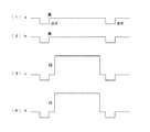
次に、垂直シャープネス回路4内部の動作について図3の波形図を用いて説明する。ビデオ入力端子3からのビデオ信号は、第1の1Hディレイライン5を通過後に第2の1Hディレイライン6に加わる。そこで、ビデオ入力端子3からのビデオ信号を図3(1)にaで、第1の1Hディレイライン5のビデオ信号を図3(2)にbで、第2の1Hディレイライン6のビデオ信号を図3(3)にcで示す。
【0019】
図3a、bのビデオ信号は、100%黒の黒信号であり、図3c、dのビデオ信号は、100%白の白信号であり連続している信号であるとする。すると、図3bとcの信号では黒から白への変化がある。このような変化が垂直シャープネスを行うべき信号変化である。つまり、図3bの信号はより黒に強調されるべきである。図3cの信号はより白に強調されるべきである。
【0020】
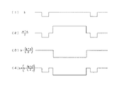
図3bの黒信号がより黒に強調される動作について図4の波形図を用いて説明する。図4(1)は信号bを示し、図4(2)は信号aと信号cの平均値を示す。図4の信号bは第1の1Hディレイライン5から得られ、図4(2)は減衰回路8から得られる。第1加算器7は、第2の1Hディレイライン6の出力信号cとビデオ信号aとを加算する。減衰回路8は、その加算結果を1/2にする。従って、図4(2)は減衰回路8から得られる。減衰回路8からの図4(2)の信号は、減算器9で図4の信号bから減算される。
【0021】
すると、減算器9の出力信号は、図4(3)のように黒方向(低いレベル)に強調された信号が得られる。そこで、この図4(3)の黒方向(低いレベル)に強調された信号を元のビデオ信号bに第2加算器11で加算すれば、図4(4)に示すように黒方向に強調された信号が作成される。尚、ビデオ信号bが完全な黒信号の場合を説明しているので、強調後の信号はマイナス方向になっている。ここで減算器9の出力信号レベルをレベル調整回路10で調整すれば図4(3)の黒方向信号の大きさを変えることができるので垂直シャープネスの強さが変えられる。
【0022】
従って、図4(1)の信号bは図4(4)の信号となり黒方向に強調された。
【0023】
次に、図3cの白信号がより白に強調される動作について図5を用いて説明する。この場合は、図3の(2)乃至(4)の信号を用いる。図5(1)は信号cを示し、図5(2)は信号bと信号dの平均値を示す。黒の場合と同様の動作が白でも起こる。図5(2)は減衰回路8から得られる。減衰回路8からの図5(2)の信号は、減算器9で図5の信号cから減算される。すると、減算器9の出力信号は、図5(3)のように白方向(高いレベル)に強調された信号が得られる。
【0024】
そこで、この図5(3)の白方向に強調された信号を元のビデオ信号cに第2加算器11で加算すれば、図5(4)に示すように白方向に強調された信号が作成される。ここで減算器9の出力信号レベルをレベル調整回路10で調整すれば図5(3)の白方向信号の大きさを変えることができるので垂直シャープネスの強さが変えられる。
【0025】
従って、図5(1)の信号cは図5(4)の信号となり白方向に強調された。このように、図3(2)から図3(3)への信号変化は、垂直シャープネス回路4の働きにより、図4(4)の信号から図5(4)の信号への変化に置き換えられた。
【0026】
垂直シャープネス回路4の出力ビデオ信号は、水平方向のシャープネスを行うシャープネス回路12に印加された後、Brightness, Contrastをかける信号処理回路13に印加される。シャープネス回路12と信号処理回路13には、マイクロコンピュータ2から視聴者の好みの制御量情報が供給される。
【0027】
従って、視聴者の好みの制御が行われたビデオ信号はY信号としてマトリクス回路14に加わる。マトリクス回路14は端子15乃至17からのR−Y信号、G−Y信号、B−Y信号と、Y信号とをマトリクスしてR、G、Bの各原色信号をつくりOSDスイッチ18に印加する。
【0028】
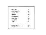
OSDスイッチ18はマトリクス回路14からのR、G、Bの各原色信号とマイクロコンピュータ2からの文字信号用のR、G、Bの各原色信号を切り換えて出力する。マイクロコンピュータ2は、図6の内容をTV画面に表示するための文字情報を発生する。マイクロコンピュータ2はキャラクタジェネレータを有する。レベル調整回路10に対する制御信号の大きさは、図6の4行目にV−SHARPとして画面上に3の強さで表示している。視聴者がこの3を変えるには端子1に加える垂直シャープネス制御信号の変えれば良い。そうすれば、マイクロコンピュータ2がレベル調整回路10の調整量を変えるとともにその度合いを表示する信号を発生し図6のV−SHARPの数値を変る。
【0029】
従って、出力端子19乃至21には、垂直シャープネスが施された画像上にマイクロコンピュータ2からの文字信号などが載ったR、G、Bの各原色信号が得られる。
【0030】
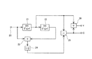
図7はコンポジットビデオ信号を輝度信号(Y)とクロマ信号(C)に分ける櫛形フィルタを示す。入力端子20にはコンポジットビデオ信号が印加される。1Hディレイライン21と1Hディレイライン22は、各々ビデオ信号を1H期間遅らせる。加算器23、減衰回路24、減算器25は、図1の加算器7、減衰回路8、減算器9と同様の動作をする。クロマ信号は1H毎に位相が反転し、輝度信号は反転しない。このため、減算器25で減算するとクロマ信号は表れるが、輝度信号は相殺されて消える。
【0031】
この減算器25からのクロマ信号をマイナスの形で元のコンポジットビデオ信号に加算器26で加算すれば、今度はクロマ信号が相殺され輝度信号のみが得られる。このように図7の櫛形フィルタは、図1の垂直シャープネス回路4と同様の構成及び動作である。そこで、本発明ではこれらの1Hディレイライン21、1Hディレイライン22、加算器23、減衰回路24、減算器25を図1のものと兼用するようにする。これにより、高価な1Hディレイラインの削減と素子数の低減ができる。
【0032】
【発明の効果】
本発明の垂直シャープネス装置によれば、ビデオ信号に対して垂直シャープネスを行うことができる。また、垂直シャープネスを視聴者の好みで変えることができ、視聴者は最適な垂直シャープネス効果を享受できる。
【0033】
また、本発明の垂直シャープネス装置によれば、垂直シャープネスの度合いをTV画面上に表示しながら視聴者が変えることができる。更に、輝度信号(Y)とクロマ信号(C)の分離用の櫛形フィルタと1Hディレイラインや回路ブロックを兼用することができる。
【図面の簡単な説明】
【図1】本発明の実施形態に係る垂直シャープネス装置のブロック図である。
【図2】従来のリモートコントロールによるTV画面上の表示形態を示す図である。
【図3】本発明の垂直シャープネス回路の動作説明に用いる波形図である。
【図4】本発明の垂直シャープネス回路の動作説明に用いる波形図である。
【図5】本発明の垂直シャープネス回路の動作説明に用いる波形図である。
【図6】本発明のリモートコントロールによるTV画面上の表示形態を示す図である。
【図7】TV受像機に使われる櫛形フィルタの動作説明に用いるブロック図である。
【符号の説明】
1 端子 2 マイクロコンピュータ 3 第1抵抗
4 垂直シャープネス回路 5 第1の1Hディレイライン
6 第2の1Hディレイライン 7 第1加算器 8 減衰回路
9 減算器 10 レベル調整回路 11 第2加算器
18 OSDスイッチ[0001]
TECHNICAL FIELD OF THE INVENTION
The present invention relates to a vertical sharpness device for performing vertical sharpness of a TV (television) screen on a video signal (luminance signal) and a TV receiver including the same, and particularly to a TV receiver having a TV receiver. The present invention relates to a vertical sharpness device capable of performing optimal vertical sharpness and a TV receiver having the same.
[0002]
[Prior art]
Conventionally, a sharpness function has been known as a function of a TV receiver. This sharpness function emphasizes the horizontal outline of an image. When the outline of an object is emphasized, the object appears to stand out. The viewer sees the object more clearly and sharply than when the outline is not emphasized. In the TV receiver, the following items can be adjusted in addition to the sharpness.
Brightness (Bright) Brightness adjustment Contrast (Contrast) Difference in brightness between white and black Color (Color) Color saturation adjustment Tint (Tint) Color adjustment For these items, the viewer of the TV receiver can Generally, it can be adjusted to a desired value. These adjustments include a case where a knob is present on the TV receiver main body and a case where the adjustment is performed by displaying an adjustment value on a TV screen by a remote control.
[0003]
As a display of the adjustment value on the TV screen by the remote control, for example, a display as shown in FIG. 2 is performed. In FIG. 2, five items, Brightness, Contrast, Sharp, Color, and Tint, are displayed from the top. In this TV receiver, it means that five items, Brightness, Contrast, Sharp, Color, and Tint, can be adjusted to the values desired by the viewer.
[0004]
Brightness is currently being adjusted, and its degree is 32. The viewer can set the
[0005]
The sharpness function of a TV receiver is described in, for example,
[0006]
[Patent Document 1]
JP-A-10-93842
[Problems to be solved by the invention]
However, in the conventional TV receiver, the viewer could not select the vertical sharpness that emphasizes the vertical contour of the image. The vertical sharpness is to enhance the vertical contour by enhancing the change in brightness from white to black or from black to white in a video signal around 1H (H is one horizontal period). is there. Also in this case, there is an effect that the object can be seen clearly as compared with the case where the outline is not emphasized.
[0008]
Vertical sharpness has the negative effect of increasing screen noise while having the effect of making the object appear clear. For this reason, when vertical sharpness is performed in an area with a weak electric field or the like, the noise on the screen becomes intense, resulting in an adverse effect.
[0009]
[Means for Solving the Problems]
The present invention has been made in view of the above-described problems of the related art, and has a terminal to which a vertical sharpness control signal is applied by a viewer of a TV receiver, a control circuit to which a vertical sharpness control signal from the terminal is applied, and A vertical sharpness circuit for adjusting the degree of vertical sharpness of the video signal according to a vertical sharpness control signal from the control circuit.
[0010]
BEST MODE FOR CARRYING OUT THE INVENTION
Next, embodiments of the present invention will be described with reference to the drawings. FIG. 1 is a block diagram of a vertical sharpness device according to an embodiment of the present invention. In the figure, 1 is a terminal to which a vertical sharpness control signal by a viewer of a TV receiver is applied, 2 is a microcomputer as a control circuit to which a vertical sharpness control signal from the
[0011]
[0012]
[0013]
A
[0014]
[0015]
Next, the operation of the vertical sharpness device of FIG. 1 will be described. The
[0016]
For this reason, vertical sharpness can be achieved by control from the
[0017]
Therefore, the viewer can set the vertical sharpness to weak or zero in an area with a weak electric field or the like. Then, in an area having a sufficient electric field strength, the vertical sharpness can be set higher. This allows the viewer to enjoy the optimal vertical sharpness effect.
[0018]
Next, the operation inside the
[0019]
The video signals of FIGS. 3A and 3B are black signals of 100% black, and the video signals of FIGS. 3C and 3D are white signals of 100% white and continuous. Then, there is a change from black to white in the signals of FIGS. 3b and c. Such a change is a signal change for which vertical sharpness is to be performed. That is, the signal of FIG. 3b should be emphasized more black. The signal in FIG. 3c should be emphasized more white.
[0020]
The operation in which the black signal of FIG. 3B is emphasized more black will be described with reference to the waveform diagram of FIG. FIG. 4A shows the signal b, and FIG. 4B shows the average value of the signal a and the signal c. 4 is obtained from the first 1H delay line 5, and FIG. 4 (2) is obtained from the attenuation circuit 8. The first adder 7 adds the output signal c of the second
[0021]
Then, as the output signal of the
[0022]
Therefore, the signal b in FIG. 4A becomes the signal in FIG. 4D and is emphasized in the black direction.
[0023]
Next, an operation in which the white signal in FIG. 3C is emphasized more white will be described with reference to FIG. In this case, the signals of (2) to (4) in FIG. 3 are used. FIG. 5A shows the signal c, and FIG. 5B shows the average value of the signal b and the signal d. The same operation as in black occurs in white. FIG. 5B is obtained from the attenuation circuit 8. The signal of FIG. 5B from the attenuation circuit 8 is subtracted by the
[0024]
Then, if the signal emphasized in the white direction in FIG. 5C is added to the original video signal c by the
[0025]
Therefore, the signal c in FIG. 5A becomes the signal in FIG. 5D and is emphasized in the white direction. Thus, the signal change from FIG. 3 (2) to FIG. 3 (3) is replaced by the change from the signal of FIG. 4 (4) to the signal of FIG. Was.
[0026]
The output video signal from the
[0027]
Therefore, the video signal controlled by the viewer's preference is applied to the
[0028]
The
[0029]
Accordingly, R, G, and B primary color signals in which a character signal and the like from the
[0030]
FIG. 7 shows a comb filter for dividing a composite video signal into a luminance signal (Y) and a chroma signal (C). A composite video signal is applied to the
[0031]
If the chroma signal from the
[0032]
【The invention's effect】
According to the vertical sharpness device of the present invention, vertical sharpness can be performed on a video signal. Also, the vertical sharpness can be changed according to the viewer's preference, and the viewer can enjoy the optimal vertical sharpness effect.
[0033]
Further, according to the vertical sharpness device of the present invention, the viewer can change the degree of the vertical sharpness while displaying the degree on the TV screen. Further, the comb filter for separating the luminance signal (Y) and the chroma signal (C) can be used as a 1H delay line or a circuit block.
[Brief description of the drawings]
FIG. 1 is a block diagram of a vertical sharpness device according to an embodiment of the present invention.
FIG. 2 is a diagram showing a display form on a TV screen by a conventional remote control.
FIG. 3 is a waveform diagram used to explain the operation of the vertical sharpness circuit of the present invention.
FIG. 4 is a waveform chart used to describe the operation of the vertical sharpness circuit of the present invention.
FIG. 5 is a waveform diagram used to describe the operation of the vertical sharpness circuit of the present invention.
FIG. 6 is a diagram showing a display form on a TV screen by the remote control of the present invention.
FIG. 7 is a block diagram used to explain the operation of a comb filter used in a TV receiver.
[Explanation of symbols]
Claims (8)
該端子からの垂直シャープネス制御信号が印加される制御回路と、
該制御回路からの垂直シャープネス制御信号に応じてビデオ信号の垂直シャープネスの度合いを調整する垂直シャープネス回路とを備えることを特徴とする垂直シャープネス装置。A terminal to which a vertical sharpness control signal by a viewer of the TV receiver is applied;
A control circuit to which a vertical sharpness control signal from the terminal is applied;
A vertical sharpness circuit for adjusting the degree of vertical sharpness of the video signal according to a vertical sharpness control signal from the control circuit.
Priority Applications (4)
| Application Number | Priority Date | Filing Date | Title |
|---|---|---|---|
| JP2002322498A JP2004159067A (en) | 2002-11-06 | 2002-11-06 | Vertical sharpness device and tv receiver provided with same |
| US10/675,632 US7161636B2 (en) | 2002-11-06 | 2003-09-30 | Vertical sharpness adjustment device and TV receiver therewith |
| KR1020030078001A KR100562823B1 (en) | 2002-11-06 | 2003-11-05 | Vertical sharpness adjustment device and tv receiver therewith |
| CNB2003101181650A CN1258280C (en) | 2002-11-06 | 2003-11-06 | Vertical sharpness adjustment device and TV receiver therewith |
Applications Claiming Priority (1)
| Application Number | Priority Date | Filing Date | Title |
|---|---|---|---|
| JP2002322498A JP2004159067A (en) | 2002-11-06 | 2002-11-06 | Vertical sharpness device and tv receiver provided with same |
Publications (1)
| Publication Number | Publication Date |
|---|---|
| JP2004159067A true JP2004159067A (en) | 2004-06-03 |
Family
ID=32171335
Family Applications (1)
| Application Number | Title | Priority Date | Filing Date |
|---|---|---|---|
| JP2002322498A Pending JP2004159067A (en) | 2002-11-06 | 2002-11-06 | Vertical sharpness device and tv receiver provided with same |
Country Status (4)
| Country | Link |
|---|---|
| US (1) | US7161636B2 (en) |
| JP (1) | JP2004159067A (en) |
| KR (1) | KR100562823B1 (en) |
| CN (1) | CN1258280C (en) |
Families Citing this family (1)
| Publication number | Priority date | Publication date | Assignee | Title |
|---|---|---|---|---|
| US8174627B2 (en) * | 2005-09-06 | 2012-05-08 | Hewlett-Packard Development Company, L.P. | Selectively masking image data |
Family Cites Families (36)
| Publication number | Priority date | Publication date | Assignee | Title |
|---|---|---|---|---|
| DE1537111B2 (en) * | 1967-07-28 | 1974-05-16 | Robert Bosch Fernsehanlagen Gmbh, 6100 Darmstadt | Method and arrangement for increasing the sharpness of the contours of a television picture by means of two-sided aperture correction of the picture-writing television signal |
| US3804980A (en) | 1972-03-01 | 1974-04-16 | Ellanin Investments | Vertical sharpness enhancement of video pictures |
| US3995108A (en) * | 1975-05-21 | 1976-11-30 | Ampex Corporation | Television aperture correction system having gateable coring means for noise cancellation |
| US4245238A (en) * | 1979-05-11 | 1981-01-13 | Rca Corporation | Non-linear processing of video image vertical detail information |
| DE2937958C2 (en) * | 1979-09-20 | 1982-03-25 | Robert Bosch Gmbh, 7000 Stuttgart | Process for horizontal and vertical contour correction |
| US4336552A (en) * | 1980-12-17 | 1982-06-22 | Sony Corporation | Vertical aperture correction circuit |
| US4365266A (en) * | 1981-04-20 | 1982-12-21 | Rca Corporation | Horizontal and vertical image detail processing of a color television signal |
| US4403246A (en) * | 1981-11-13 | 1983-09-06 | Rca Corporation | Vertical detail enhancement on/off switch |
| JPS60114090A (en) * | 1983-11-26 | 1985-06-20 | Toshiba Corp | Vertical contour correction device |
| US4612567A (en) * | 1984-05-03 | 1986-09-16 | Rca Corporation | Television receiver using non-interlaced scanning format with vertical detail enhancement and motion compensation |
| JPS6184972A (en) * | 1984-10-03 | 1986-04-30 | Hitachi Ltd | Vertical emphasis circuit of video signal |
| US4802010A (en) * | 1986-11-14 | 1989-01-31 | North American Philips Consumer Electronics Corp. | Method and apparatus for generating an adaptive peaking signal increasing the sharpness of a video signal |
| US4916538A (en) * | 1987-02-06 | 1990-04-10 | Carver Corporation | Apparatus and methods for enhancing a video display |
| GB2223142B (en) * | 1988-09-23 | 1993-01-06 | Sony Corp | Separating components of composite digital video signals |
| JPH02121574A (en) * | 1988-10-31 | 1990-05-09 | Nippon Television Network Corp | Improvement system for amplitude characteristics of television vertical frequency signal |
| US4962419A (en) * | 1989-02-13 | 1990-10-09 | Eastman Kodak Company | Detail processing method and apparatus providing uniform processing of horizontal and vertical detail components |
| KR920005018B1 (en) * | 1989-07-20 | 1992-06-22 | 삼성전자 주식회사 | Motional adative vertical contour compensative circuit in tv receiver |
| JPH0445671A (en) * | 1990-06-12 | 1992-02-14 | Sony Corp | Contour emphasis circuit for television signal |
| CA2089357C (en) * | 1990-09-14 | 2001-06-12 | Andrew Denys Hackett | Method and apparatus for improving vertical sharpness of picture tubes |
| US5268758A (en) * | 1990-09-26 | 1993-12-07 | Matsushita Electric Industrial Co., Ltd. | Horizontal line interpolation circuit and image pickup apparatus including it |
| US5121209A (en) * | 1990-10-01 | 1992-06-09 | Rca Licensing Corporation | Sharpness control for a television image |
| WO1993010641A1 (en) * | 1991-11-15 | 1993-05-27 | Snell & Wilcox | Colour television signal processing |
| US5428398A (en) * | 1992-04-10 | 1995-06-27 | Faroudja; Yves C. | Method and apparatus for producing from a standard-bandwidth television signal a signal which when reproduced provides a high-definition-like video image relatively free of artifacts |
| JP3336630B2 (en) * | 1992-06-23 | 2002-10-21 | ソニー株式会社 | Video signal processing circuit |
| JP3196354B2 (en) * | 1992-10-13 | 2001-08-06 | 株式会社日立製作所 | Contour correction circuit and imaging device |
| JP3076810B2 (en) * | 1994-01-20 | 2000-08-14 | モトローラ株式会社 | Vertical contour correction circuit |
| US5446503A (en) * | 1994-04-11 | 1995-08-29 | Mitsubishi Semiconductor America, Inc. | Vertical detail enhancement with stepped return coring |
| US5587745A (en) * | 1994-07-05 | 1996-12-24 | Thomson Consumer Electronics, Inc. | Adjustment of scan velocity modulation concurrent with the amount of transition rise time, pre-shoot, and overshoot of a video signal |
| US5467145A (en) * | 1994-10-26 | 1995-11-14 | Samsung Electronics Co., Ltd. | Circuitry for enhancing detail in color video signals |
| US5581306A (en) * | 1995-02-08 | 1996-12-03 | Texas Instruments Incorporated | Vertical scaling for digital image data with aperture correction |
| EP0796540B1 (en) * | 1995-10-05 | 2000-05-17 | Faroudja Laboratories, Inc. | Method for procucing from a standard-bandwidth color television signal a color video signal with extended vertical definition |
| JPH1093842A (en) | 1996-08-09 | 1998-04-10 | Lg Electron Inc | Tv signal processing circuit |
| US6330038B1 (en) * | 1997-03-31 | 2001-12-11 | Compaq Computer Corporation | Video sharpness control device and method |
| DE69838779D1 (en) * | 1997-08-26 | 2008-01-10 | Matsushita Electric Ind Co Ltd | CORRECTION DEVICE FOR VERTICAL CONTOURS |
| US6034742A (en) * | 1997-10-27 | 2000-03-07 | Sony Corporation | Adaptive sharpness enhancement for a multi-frequency scanning monitor |
| US6377313B1 (en) * | 1999-09-02 | 2002-04-23 | Techwell, Inc. | Sharpness enhancement circuit for video signals |
-
2002
- 2002-11-06 JP JP2002322498A patent/JP2004159067A/en active Pending
-
2003
- 2003-09-30 US US10/675,632 patent/US7161636B2/en not_active Expired - Fee Related
- 2003-11-05 KR KR1020030078001A patent/KR100562823B1/en not_active IP Right Cessation
- 2003-11-06 CN CNB2003101181650A patent/CN1258280C/en not_active Expired - Fee Related
Also Published As
| Publication number | Publication date |
|---|---|
| KR20040040385A (en) | 2004-05-12 |
| US20040085481A1 (en) | 2004-05-06 |
| US7161636B2 (en) | 2007-01-09 |
| CN1501690A (en) | 2004-06-02 |
| KR100562823B1 (en) | 2006-03-23 |
| CN1258280C (en) | 2006-05-31 |
Similar Documents
| Publication | Publication Date | Title |
|---|---|---|
| JP5370761B2 (en) | Video signal processing device and display device | |
| KR20070111389A (en) | Image correction circuit, image correction method, and image display | |
| US4716462A (en) | Motion adaptive television signal processing system | |
| US6346970B1 (en) | Two-dimensional adjustable flicker filter | |
| JP2004326082A (en) | Display controller and display device | |
| JP2003348377A (en) | Image display device and image processing apparatus, and image processing method | |
| JP2004159067A (en) | Vertical sharpness device and tv receiver provided with same | |
| JPH077685A (en) | Television receiver | |
| JP2001125557A (en) | Hue and saturation regulating device and image display device and hue and saturation regulating method | |
| KR20050004911A (en) | Image processing | |
| JP3173063B2 (en) | Color adaptive contour enhancement device and method | |
| KR100335618B1 (en) | Color display device having color temperature conversion function and method of changing color temperature | |
| JPH05224641A (en) | Video display device | |
| TW202008311A (en) | Image saturation adjusting method and device | |
| JP2003283874A (en) | Contour correcting system for display device | |
| JP3714877B2 (en) | Image display device and program | |
| JP4292135B2 (en) | Image display device | |
| JPH04126470A (en) | Contour emphasis circuit | |
| JP2006030998A (en) | Hue and saturation adjusting device, image display device, and hue and saturation adjusting method | |
| JP3600678B2 (en) | Television signal processing method and television signal processing device | |
| WO2000010326A2 (en) | Two-dimensional adjustable flicker filter | |
| JPH03151790A (en) | Contour correction circuit for color signal | |
| JPH07143516A (en) | Video signal compressor | |
| JP2003009172A (en) | Image signal processing circuit | |
| JP2004080269A (en) | Video signal processing apparatus |
Legal Events
| Date | Code | Title | Description |
|---|---|---|---|
| A621 | Written request for application examination |
Free format text: JAPANESE INTERMEDIATE CODE: A621 Effective date: 20051101 |
|
| RD01 | Notification of change of attorney |
Free format text: JAPANESE INTERMEDIATE CODE: A7421 Effective date: 20051226 |
|
| A977 | Report on retrieval |
Free format text: JAPANESE INTERMEDIATE CODE: A971007 Effective date: 20080214 |
|
| A131 | Notification of reasons for refusal |
Free format text: JAPANESE INTERMEDIATE CODE: A131 Effective date: 20080226 |
|
| A521 | Written amendment |
Free format text: JAPANESE INTERMEDIATE CODE: A523 Effective date: 20080423 |
|
| A131 | Notification of reasons for refusal |
Free format text: JAPANESE INTERMEDIATE CODE: A131 Effective date: 20080527 |
|
| A02 | Decision of refusal |
Free format text: JAPANESE INTERMEDIATE CODE: A02 Effective date: 20080930 |

