CN202320463U - Electromobile - Google Patents
Electromobile Download PDFInfo
- Publication number
- CN202320463U CN202320463U CN2011204107743U CN201120410774U CN202320463U CN 202320463 U CN202320463 U CN 202320463U CN 2011204107743 U CN2011204107743 U CN 2011204107743U CN 201120410774 U CN201120410774 U CN 201120410774U CN 202320463 U CN202320463 U CN 202320463U
- Authority
- CN
- China
- Prior art keywords
- wheel
- steering
- assembly
- battery
- wheel steering
- Prior art date
- Legal status (The legal status is an assumption and is not a legal conclusion. Google has not performed a legal analysis and makes no representation as to the accuracy of the status listed.)
- Expired - Lifetime
Links
Images
Landscapes
- Toys (AREA)
Abstract
The utility model discloses an electromobile, which is composed of four wheels (1), two wheel driving assemblies (2), four wheel steering assemblies (3), a steering wheel assembly (4), a controller (5), a battery pack (6) and a frame (7), wherein the four wheels (1) are respectively installed on the four wheel steering assemblies (3) on the frame (7); the two wheels (1) are respectively connected with one wheel driving assembly (2); and the steering wheel assembly (4), the controller (5) and the battery pack (6) are respectively installed on the frame (7). When the electromobile works, the steering wheel assembly (4) controls the wheel steering assemblies (3) by the controller (5) to rotate the wheels (1) to an appointed angle position, the front and rear wheels (1) all can independently steer, and the electromobile can change a driving mode to carry out lateral driving and turn around in situ.
Description
One, technical field
The utility model relates to a kind of vehicle, especially a kind of battery-driven car.
Two, background technology
The battery-driven car that uses on the market at present, its bearing circle direct drive front-wheel steering, rear wheel can not turn to; And can only go by fore-and-aft direction; Can not carry out cross running by the conversion driving mode,, can not go flexibly, park or turn around in the very limited place of traffic space resource.
Three, the utility model content
The purpose of the utility model just provides that a kind of front and back wheel all can turn to and convertible driving mode carries out the battery-driven car of cross running and spot turn.
The purpose of the utility model is achieved in that it is made up of four wheels, two wheel driving assemblies, four wheel steering assemblies, steering wheel assembly, controller, battery pack and vehicle frames.Four wheel steering assemblies are installed in respectively on the vehicle frame, and four jiaos of places, all around respectively are provided with one, and four wheels are installed in respectively on four wheel steering assemblies; Four wheel steering assemblies are made up of wheel installation rectangular axes, wheel steering angle detection piece, wheel steering gear case respectively; Wheel steering angle detection piece is installed on the wheel rectangular axes, and affixed with wheel installation rectangular axes, the wheel steering assembly is under the wheel steering gear case drives; Drive wheel, independent steering; The steering angle zone is spent to 150 degree scopes 0; In four wheels, wherein two wheels connect with two wheel driving assemblies respectively, and these two wheel diagonal are dynamic wheel; Wheel is wheel under wheel driving assembly drives; Steering wheel assembly, controller, battery pack are installed in respectively on the vehicle frame, and battery pack is that wheel driving assembly, wheel steering assembly, steering wheel assembly, controller provide electric power.During work, wheel steering angle detection piece detects wheel angle position state, and steering wheel assembly makes wheel forward the angle position of appointment to through the work of controller control wheel steering gear case then.
Owing to adopt such scheme, during the straight-line travelling of battery-driven car front and back, four wheel steering assemblies forward four wheels to 0 angle respectively, and battery-driven car can advance or retreat and go; During the battery-driven car left steering, two the wheel steering assemblies in car back are not worked, two the wheel steering assemblies work in car front, simultaneously left-handed turning to, battery-driven car left-handed turning to; The battery-driven car right-hand turning to the time, two the wheel steering assemblies in car back are not worked, two the wheel steering assemblies work in car front, simultaneously right-hand turning to, battery-driven car right-hand turning to; Battery-driven car is when tilted direction goes left, and four wheel steering assemblies forward four vehicle wheel component conter clockwises to the miter angle degree respectively, and car can go; Battery-driven car is when tilted direction goes to the right, and four wheel steering assemblies forward four wheel cws to the miter angle degree respectively, and car can go; During the battery-driven car cross running; Preceding left wheel steering assembly forwards preceding left wheel, the right wheel cw in back to an angle of 90 degrees degree respectively with the right wheel steering assembly in back; Before right wheel steering assembly forward preceding left wheel, the right wheel conter clockwise in back to an angle of 90 degrees degree respectively with back left wheel steering assembly, car can carry out cross running or park; When battery-driven car is turn-taked on the spot; Preceding left wheel steering assembly forwards preceding left wheel and the right wheel cw in back to the miter angle degree respectively with the right wheel steering assembly in back; Before right wheel steering assembly forward preceding right wheel and back left wheel conter clockwise to the miter angle degree respectively with back left wheel steering assembly, car can be turn-taked on the spot, turned around; Very go very flexible in limited place at traffic resource.
Four, description of drawings
Below in conjunction with accompanying drawing and embodiment the utility model is further specified.
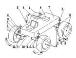
Fig. 1 be the utility model structural representation.
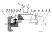
Fig. 2 is that the local structure of the utility model are cutd open and shown scheme drawing.
Fig. 3 is the front and back walking working state schematic representation of the utility model
Fig. 4 is the left oblique walking working state schematic representation of the utility model
Fig. 5 is the right oblique walking working state schematic representation of the utility model
Fig. 6 is the left-hand rotation circle working state schematic representation of the utility model
Fig. 7 is the right-hand rotation circle working state schematic representation of the utility model
Fig. 8 is the horizontal walking working state schematic representation of the utility model
Fig. 9 is the working state schematic representation of turn-taking on the spot of the utility model
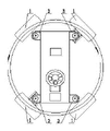
Second embodiment scheme drawing of Figure 10 the utility model
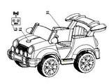
The 3rd the embodiment scheme drawing of Figure 11 the utility model
Among the figure 1, wheel 2, wheel driving assembly 3, wheel steering assembly 4, steering wheel assembly 5, controller 6, battery pack 7, vehicle frame 8, wheel install rectangular axes 9, wheel steering angle detection piece 10, wheel steering gear case 11, vehicle body 12, receiver of remote-control sytem 13, perambulator remote controller
Five, the specific embodiment
In Fig. 1, battery-driven car is made up of four wheels [1], two wheel driving assemblies [2], four wheel steering assemblies [3], steering wheel assembly [4], controller [5], battery pack [6] and vehicle frame [7].Four wheel steering assemblies [3] are installed in respectively on the vehicle frame [7]; Four jiaos of places, all around respectively are provided with one; Four wheels [1] are installed in respectively on four wheel steering assemblies [3], and four wheel steering assemblies [3] are made up of wheel installation rectangular axes [8], wheel steering angle detection piece [9], wheel steering gear case [10] respectively, and wheel steering angle detection piece [9] is installed on the wheel rectangular axes [8]; Affixed with wheel rectangular axes [8]; Four wheels [1] drive down at wheel steering spare assembly [3] respectively, independent steering, and steering angle is spent to 150 degree scopes 0; Two wheel driving assemblies [2] are installed in respectively on two wheel steering assemblies [3], and the diagonal angle distributes, and connect with a wheel [1] respectively simultaneously, and wheel [1] is wheel under wheel driving assembly [2] drives; Steering wheel assembly [4], controller [5], battery pack [6] are installed in respectively on the vehicle frame [7], and battery pack [4] is that wheel driving assembly [2], wheel steering assembly [3], steering wheel assembly [4], controller [5] provide electric power.During work, wheel steering angle detection piece [9] detects wheel [1] angle position state, and steering wheel assembly [4] makes wheel [1] forward the angle position of appointment to through controller [5] control wheel steering gear case [10] work then.
In Fig. 2; Wheel steering assembly [3] is installed on the vehicle frame [7], and wheel [1] is installed on the wheel steering assembly [3], and wheel steering assembly [3] is made up of wheel installation rectangular axes [8], wheel steering angle detection piece [9], wheel steering gear case [10]; Wheel steering angle detection piece [9] is installed on the wheel rectangular axes [8]; Affixed with wheel rectangular axes [8], wheel driving assembly [2] is installed on the wheel steering assembly [3], connects with a wheel [1].
In Fig. 3, during the straight-line travelling of battery-driven car front and back, four wheel steering assemblies [3] forward four wheels [1] to 0 angle respectively, advance then, retreat and go.During the battery-driven car left steering, left and right sides front vehicle wheel steering assembly [3] forwards left and right sides front vehicle wheel [1] conter clockwise to the miter angle degree respectively, goes then; During the battery-driven car right steering, left and right sides front vehicle wheel steering assembly [3] forwards left and right sides front vehicle wheel [1] cw to the miter angle degree respectively, goes then.
In Fig. 4, battery-driven car is oblique left when going, and four wheel steering assemblies [3] forward four wheels [1] conter clockwise to the miter angle degree respectively, go then.
In Fig. 5, battery-driven car is oblique to the right when going, and four wheel steering assemblies [3] forward four wheels [1] cw to the miter angle degree respectively, go then.
In Fig. 6, when battery-driven car was turn-taked left, preceding left and right wheels steering assembly [3] forwarded wheel [1] conter clockwise to the miter angle degree respectively, and back left and right wheels steering assembly [3] forwards wheel [1] cw to the miter angle degree respectively, goes then.
In Fig. 7, when battery-driven car was turn-taked left, preceding left and right wheels steering assembly [3] forwarded wheel [1] cw to the miter angle degree respectively, and back left and right wheels steering assembly [3] forwards wheel [1] conter clockwise to the miter angle degree respectively, goes then.
In Fig. 8; During the battery-driven car cross running; Preceding left wheel steering assembly [3] and the right wheel steering assembly in back [3] forward preceding left wheel [1], back right wheel [1] cw to an angle of 90 degrees degree respectively; Before right wheel steering assembly [3] and back left wheel steering assembly [3] forward preceding left wheel [1], back right wheel [1] conter clockwise to an angle of 90 degrees degree respectively, carry out the cross running operation then.
In Fig. 9; When battery-driven car is turn-taked on the spot; Preceding left wheel steering assembly [3] and the right wheel steering assembly in back [3] forward preceding left wheel [1] and back right wheel [1] cw to the miter angle degree respectively; Before right wheel steering assembly [3] and back left wheel steering assembly [3] forward preceding left wheel [1] and back right wheel [1] conter clockwise to the miter angle degree, the operation of turn-taking on the spot then respectively.
In Figure 10, two wheel steering assemblies [3] are connected as a single entity about the electric bicycle front, and two wheel steering assemblies [3] are connected as a single entity about the back, are installed in respectively on the vehicle frame [7].
In Figure 11; The battery-driven car vehicle body is made as child seats electric toy car vehicle body [11]; Children just can take advantage of a battery-driven car to operate, and on the vehicle body [11] receiver of remote-control sytem [12] have been installed simultaneously, and perambulator remote controller [13] is just through receiver of remote-control sytem [12] remote control child seats electric toy car.
Claims (6)
1. battery-driven car; It is made up of four wheels [1], two wheel driving assemblies [2], four wheel steering assemblies [3], steering wheel assembly [4], controller [5], battery pack [6] and vehicle frame [7]; It is characterized in that: four wheel steering assemblies [3] are installed in respectively on the vehicle frame [7]; The all around respectively is provided with one for four jiaos; Wheel driving assembly [2] is installed on the wheel steering assembly [3]; Four wheels [1] are installed in respectively on four wheel steering assemblies [3], and steering wheel assembly [4], controller [5], battery pack [6] are installed in respectively on the vehicle frame [7], and battery pack [6] is that steering wheel assembly [4], controller [5], wheel driving assembly [2], wheel steering assembly [3] provide electric power.
2. battery-driven car according to claim 1; It is characterized in that: four wheel steering assemblies [3] are made up of wheel installation rectangular axes [8], wheel steering angle detection components [9], wheel steering gear case [10] respectively; Wheel steering assembly [3] is under wheel steering gear case [10] drives; Drive wheel [1] and rotate independent steering.
3. battery-driven car according to claim 1 is characterized in that: in four wheels [1], wherein two wheels [1] connect with two wheel driving assemblies [2] respectively, and this two wheels [1] diagonal is dynamic wheel.
4. battery-driven car according to claim 1 is characterized in that: left and right sides front vehicle wheel steering assembly [3] is connected as a single entity, and left and right sides rear wheel steering assembly [3] is connected as a single entity.
5. battery-driven car according to claim 1 is characterized in that: electric bicycle is as child seats electric toy car vehicle body [11].
6. battery-driven car according to claim 1 is characterized in that: battery-driven car is provided with receiver of remote-control sytem [12].
Priority Applications (1)
| Application Number | Priority Date | Filing Date | Title |
|---|---|---|---|
| CN2011204107743U CN202320463U (en) | 2011-10-25 | 2011-10-25 | Electromobile |
Applications Claiming Priority (1)
| Application Number | Priority Date | Filing Date | Title |
|---|---|---|---|
| CN2011204107743U CN202320463U (en) | 2011-10-25 | 2011-10-25 | Electromobile |
Publications (1)
| Publication Number | Publication Date |
|---|---|
| CN202320463U true CN202320463U (en) | 2012-07-11 |
Family
ID=46432454
Family Applications (1)
| Application Number | Title | Priority Date | Filing Date |
|---|---|---|---|
| CN2011204107743U Expired - Lifetime CN202320463U (en) | 2011-10-25 | 2011-10-25 | Electromobile |
Country Status (1)
| Country | Link |
|---|---|
| CN (1) | CN202320463U (en) |
Cited By (3)
| Publication number | Priority date | Publication date | Assignee | Title |
|---|---|---|---|---|
| CN107215386A (en) * | 2017-05-05 | 2017-09-29 | 清华大学 | The electric vehicle system that a kind of four motorized wheels and independent omnidirectional turn to |
| CN111170777A (en) * | 2019-12-26 | 2020-05-19 | 山东省农业机械科学研究院 | Side-mounted traction turning device |
| CN112092896A (en) * | 2020-08-11 | 2020-12-18 | 盐城工学院 | Locomotive full-steering control system and control method thereof |
-
2011
- 2011-10-25 CN CN2011204107743U patent/CN202320463U/en not_active Expired - Lifetime
Cited By (4)
| Publication number | Priority date | Publication date | Assignee | Title |
|---|---|---|---|---|
| CN107215386A (en) * | 2017-05-05 | 2017-09-29 | 清华大学 | The electric vehicle system that a kind of four motorized wheels and independent omnidirectional turn to |
| CN111170777A (en) * | 2019-12-26 | 2020-05-19 | 山东省农业机械科学研究院 | Side-mounted traction turning device |
| CN111170777B (en) * | 2019-12-26 | 2022-06-24 | 山东省农业机械科学研究院 | Side-mounted traction turning device |
| CN112092896A (en) * | 2020-08-11 | 2020-12-18 | 盐城工学院 | Locomotive full-steering control system and control method thereof |
Similar Documents
| Publication | Publication Date | Title |
|---|---|---|
| CN102351007A (en) | Multifunctional electric vehicle | |
| KR101218337B1 (en) | The three-wheel electric vehicle | |
| CN113044109A (en) | Four-wheel independent drive independent steering chassis | |
| WO2011031992A3 (en) | Personal transport vehicle | |
| CN202320463U (en) | Electromobile | |
| CN203186411U (en) | Four-wheel electric scooter | |
| CN102745226B (en) | Electric sedan with swing door and capable of turning fixedly | |
| CN103608238A (en) | Automated guided vehicle | |
| CN103407484B (en) | A kind of tricycle rear wheel drive steering control system | |
| CN202089196U (en) | Direction control mechanism of electric bicycle for child | |
| CN203283312U (en) | Hinged-type anti-explosion diesel engine trackless rubber-tired vehicle capable of being driven in two-way mode | |
| CN203832673U (en) | Four-wheeled walking mechanism | |
| CN204319757U (en) | A kind of vehicle structure | |
| CN203996512U (en) | A kind of electric bus of fat pipe | |
| CN207173831U (en) | Children's electric motor vehicle | |
| CN207758542U (en) | Split type dual-drive electric automobile chassis | |
| CN201415741Y (en) | Multifunction electric toy car | |
| CN203111308U (en) | Mechanical steering device and electric automobile using same | |
| CN202186461U (en) | Four-wheeled electric toy vehicle | |
| CN201415740Y (en) | Multifunction electric toy car with locking positioning mechanism | |
| CN203611729U (en) | Independent drive system of double-hub motor of electric automobile | |
| CN201980013U (en) | Ball-shaped wheel driving and traveling mechanism | |
| US20110049827A1 (en) | Carriage gravity center guidance system for delivery vehicle | |
| CN218986754U (en) | AGV dolly chassis based on drive differential steering mechanism | |
| CN203611782U (en) | Electric car control system driven by double rear-wheel hub motors |
Legal Events
| Date | Code | Title | Description |
|---|---|---|---|
| C14 | Grant of patent or utility model | ||
| GR01 | Patent grant | ||
| CX01 | Expiry of patent term |
Granted publication date: 20120711 |
|
| CX01 | Expiry of patent term |


