CN201498566U - Battery charger shell - Google Patents
Battery charger shell Download PDFInfo
- Publication number
- CN201498566U CN201498566U CN2009203029260U CN200920302926U CN201498566U CN 201498566 U CN201498566 U CN 201498566U CN 2009203029260 U CN2009203029260 U CN 2009203029260U CN 200920302926 U CN200920302926 U CN 200920302926U CN 201498566 U CN201498566 U CN 201498566U
- Authority
- CN
- China
- Prior art keywords
- box body
- battery charger
- cable
- fixture block
- connecting hole
- Prior art date
- Legal status (The legal status is an assumption and is not a legal conclusion. Google has not performed a legal analysis and makes no representation as to the accuracy of the status listed.)
- Expired - Fee Related
Links
Images
Classifications
-
- Y—GENERAL TAGGING OF NEW TECHNOLOGICAL DEVELOPMENTS; GENERAL TAGGING OF CROSS-SECTIONAL TECHNOLOGIES SPANNING OVER SEVERAL SECTIONS OF THE IPC; TECHNICAL SUBJECTS COVERED BY FORMER USPC CROSS-REFERENCE ART COLLECTIONS [XRACs] AND DIGESTS
- Y02—TECHNOLOGIES OR APPLICATIONS FOR MITIGATION OR ADAPTATION AGAINST CLIMATE CHANGE
- Y02E—REDUCTION OF GREENHOUSE GAS [GHG] EMISSIONS, RELATED TO ENERGY GENERATION, TRANSMISSION OR DISTRIBUTION
- Y02E60/00—Enabling technologies; Technologies with a potential or indirect contribution to GHG emissions mitigation
- Y02E60/10—Energy storage using batteries
Landscapes
- Charge And Discharge Circuits For Batteries Or The Like (AREA)
Abstract
The utility model provides a battery charger shell which comprises a box body. A cable connecting hole is formed on the box body; cables of the battery charger passing through the cable connecting hole are connected with elements of the battery charger; the box body comprises an upper box body and a lower box body connected with the upper box body; a sealing ring made of soft materials is arranged at the connection part of the upper and the lower box bodies; a clamping slot is formed in the cable connecting hole of the box body; an elastic clamping block is arranged at the end part of the cable close to the battery charger; an elastic sealing block is further arranged on the cable close to the inner side of the elastic clamping block; the elastic clamping block holding down the elastic sealing block is in clamping and drawing connection with the clamping slot; and a press block used for propping against the elastic clamping block is further arranged on the outer side of the elastic clamping block and connected with the box body. The battery charger shell has the advantages of good sealing performance, good shockproof effect and the like.
Description
Technical field
The utility model relates to a kind of battery charger parts, especially a kind of battery charger shell.
Background technology
Battery charger normally is used for used batteries such as mobile phone, camera are charged; Battery charger commonly used is not because body seal is not tight, in use for some time, often because its inner inlet or make moist, in use, causes the short circuit of battery charger internal electronic component or electric leakage takes place and security incident takes place; Again because battery charger lacks anti-seismic structure, in collision process or when dropping because of carelessness, be easy to cause the damage of device internal electronic component of charging the battery.
In order to overcome the existing fault of construction of above-mentioned battery charger, part manufacturer seals the battery charger shell by adopt the mode of encapsulating or ultrasonic bonding in battery charger shell upper and lower box body junction, though the sealing method can well seal battery charger, the sealing mode has destructiveness to the upper and lower box body junction; And this kind battery charger does not also overcome the defective that battery charger is easily broken, and therefore, is necessary the battery charger shell of this kind structure is improved.
The utility model content
The technical problems to be solved in the utility model provides a kind of battery charger shell, and the tight and sealing of this battery charger body seal can not damage the battery charger shell, also is difficult for breaking.
In order to solve the problems of the technologies described above, the utility model adopts following technical proposals: this battery charger shell comprises box body, described box body is provided with the cable connecting hole, the cable of battery charger passes this cable connecting hole and links to each other with the components and parts of the battery charger of described box body inside, described box body comprises upper cartridge body and the lower box body that links to each other with described upper cartridge body, be provided with by the made sealing ring of flexible material at described upper cartridge body and lower box body junction, in the cable connecting hole of described box body, be provided with draw-in groove, be provided with the elasticity fixture block suitable at cable and damper ends place, also be provided with the elastic packing piece near on the cable of described elasticity fixture block inboard with described draw-in groove near battery charger; Described elasticity fixture block compress described elastic packing piece and with described draw-in groove clip mutually, also be provided with in order to briquetting in the described elasticity fixture block outside against described elasticity fixture block, described briquetting links to each other with described box body.
According to design concept of the present utility model, on described box body, also offer in order to the installing hole of indicator light to be installed, described indicator light is installed in this installing hole, lampshade in order to the sealing indicator light is installed in the installing hole of described indicator light outside, is provided with elastic ring between described lampshade and the described installing hole.
According to design concept of the present utility model, in described box body, also be provided with circuit board, the junction of described circuit board and box body is provided with a plurality of flexure strips.
According to design concept of the present utility model, described box body links to each other by bolt with described circuit board, and described flexure strip passes the described box body of the described bolt seal position that is connected with described circuit board.
Compared with prior art, the utlity model has following beneficial effect: because battery charger shell of the present utility model is last, the lower box body junction, the cable connection hole of box body, positions such as the installing hole place of indicator light seal, sealing adopts sealing ring, sealing block, the mode of elastic packings such as diaphragm seal, its good sealing effect, and can not damage the battery charger shell, again because sealing ring, sealing block, diaphragm seals etc. are made by elastomeric material, therefore, careless and founder ground etc. local time at the battery charger shell, it can play the elastic buffer effect to this battery charger shell, and then preventing that this battery charger from being broken, shockproof effect is good.
Description of drawings
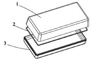
Fig. 1 is the three-dimensional decomposition texture schematic diagram of the utility model box body;
Fig. 2 is the three-dimensional decomposition texture schematic diagram of the box body of the utility model cable junction;
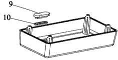
Fig. 3 is the three-dimensional decomposition texture schematic diagram of the box body at the utility model indicator light place;
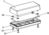
Fig. 4 is the three-dimensional decomposition texture schematic diagram of the utility model that circuit board is installed.
Embodiment
Referring to Fig. 1, battery charger shell of the present utility model comprises box body, described box body comprises upper cartridge body 1 and lower box body 3, described upper cartridge body 1 is connected with lower box body 3, is provided with sealing ring 2 at described upper cartridge body 1 and lower box body 3 junctions, and sealing ring 2 is preferably made by flexible material.
Referring to Fig. 2, box body of the present utility model is provided with cable connecting hole 11, is provided with draw-in groove in this cable connecting hole 11; The cable 12 of battery charger passes this cable connecting hole 11 and links to each other with the components and parts (figure does not show) of the battery charger of described box body inside, be provided with the elasticity fixture block 7 suitable at place, cable 12 ends, also be provided with elastic packing piece 6 near on the cable 12 of described elasticity fixture block 7 inboards with described draw-in groove near battery charger; Described elasticity fixture block 12 compresses described elastic packing piece 6 clips in described draw-in groove position, also be provided with briquetting 5,8 in described elasticity fixture block 7 outsides, this briquetting 5,8 is on being fixed on box body the time, it is in order to against described elasticity fixture block 7, make this elasticity fixture block 7 firm be fixed on this cable connecting hole 11 positions, simultaneously, 6 pairs of these holes of this elastic packing piece seal.
Referring to Fig. 3, on described box body, also offer installing hole (figure does not show) in order to indicator light to be installed, described indicator light is installed in this installing hole, lampshade 9 is installed in the installing hole of described indicator light outside, between lampshade and described installing hole, be provided with elastic ring 10, wherein, lampshade 9 and elastic ring match in order to the sealing indicator light.
Referring to Fig. 4, in described box body, also be provided with circuit board 13, described box body links to each other by bolt 15 with described circuit board 13, described circuit board 13 is provided with a plurality of flexure strips 16 with the junction of box body, and described flexure strip 16 passes the position that the described box body of described bolt 15 sealings is connected with described circuit board 13.
In sum, because the utility model seals in the positions such as cable connecting hole 11 places of upper and lower box body 1,3 junctions, box body, sealing adopts the mode of elastic packing, its good sealing effect, and can not damage, and founder ground etc. local time, elastic sealing element can play the elastic buffer effect to this battery charger shell in that the battery charger shell is careless the battery charger shell, and then prevent that this battery charger from being broken, have the good advantage of shockproof effect.
Claims (4)
1. battery charger shell, comprise box body, described box body is provided with the cable connecting hole, the cable of battery charger passes this cable connecting hole and links to each other with the components and parts of the battery charger of described box body inside, described box body comprises upper cartridge body and the lower box body that links to each other with described upper cartridge body, it is characterized in that, be provided with by the made sealing ring of flexible material at described upper cartridge body and lower box body junction, in the cable connecting hole of described box body, be provided with draw-in groove, be provided with the elasticity fixture block suitable at cable and damper ends place, also be provided with the elastic packing piece near on the cable of described elasticity fixture block inboard with described draw-in groove near battery charger; Described elasticity fixture block compress described elastic packing piece and with described draw-in groove clip mutually, also be provided with in order to briquetting in the described elasticity fixture block outside against described elasticity fixture block, described briquetting links to each other with described box body.
2. battery charger shell as claimed in claim 1, it is characterized in that, on described box body, also offer in order to the installing hole of indicator light to be installed, described indicator light is installed in this installing hole, lampshade in order to the sealing indicator light is installed in the installing hole of described indicator light outside, is provided with elastic ring between described lampshade and the described installing hole.
3. battery charger shell as claimed in claim 1 or 2 is characterized in that, also is provided with circuit board in described box body, and the junction of described circuit board and box body is provided with a plurality of flexure strips.
4. battery charger shell as claimed in claim 3 is characterized in that, described box body links to each other by bolt with described circuit board, and described flexure strip passes the described box body of the described bolt seal position that is connected with described circuit board.
Priority Applications (1)
| Application Number | Priority Date | Filing Date | Title |
|---|---|---|---|
| CN2009203029260U CN201498566U (en) | 2009-05-07 | 2009-05-07 | Battery charger shell |
Applications Claiming Priority (1)
| Application Number | Priority Date | Filing Date | Title |
|---|---|---|---|
| CN2009203029260U CN201498566U (en) | 2009-05-07 | 2009-05-07 | Battery charger shell |
Publications (1)
| Publication Number | Publication Date |
|---|---|
| CN201498566U true CN201498566U (en) | 2010-06-02 |
Family
ID=42441766
Family Applications (1)
| Application Number | Title | Priority Date | Filing Date |
|---|---|---|---|
| CN2009203029260U Expired - Fee Related CN201498566U (en) | 2009-05-07 | 2009-05-07 | Battery charger shell |
Country Status (1)
| Country | Link |
|---|---|
| CN (1) | CN201498566U (en) |
Cited By (2)
| Publication number | Priority date | Publication date | Assignee | Title |
|---|---|---|---|---|
| CN105048530A (en) * | 2015-05-12 | 2015-11-11 | 天长市优信电器设备有限公司 | Electric vehicle charger housing |
| CN113161670A (en) * | 2021-03-31 | 2021-07-23 | 海洋王(东莞)照明科技有限公司 | Explosion-proof battery box |
-
2009
- 2009-05-07 CN CN2009203029260U patent/CN201498566U/en not_active Expired - Fee Related
Cited By (3)
| Publication number | Priority date | Publication date | Assignee | Title |
|---|---|---|---|---|
| CN105048530A (en) * | 2015-05-12 | 2015-11-11 | 天长市优信电器设备有限公司 | Electric vehicle charger housing |
| CN113161670A (en) * | 2021-03-31 | 2021-07-23 | 海洋王(东莞)照明科技有限公司 | Explosion-proof battery box |
| CN113161670B (en) * | 2021-03-31 | 2023-08-22 | 深圳市海洋王石油照明技术有限公司 | Explosion-proof battery box |
Similar Documents
| Publication | Publication Date | Title |
|---|---|---|
| CN201549541U (en) | Battery cover structure | |
| CN201498566U (en) | Battery charger shell | |
| CN203760538U (en) | Battery box with failure diagnose interface for lithium battery module | |
| CN203135005U (en) | Wiring assembly | |
| CN201717437U (en) | Solar energy photovoltaic module connector | |
| CN204516810U (en) | Cylindricality lithium ion battery cover board | |
| CN204291661U (en) | Wireless transmission box | |
| CN202474397U (en) | Underwater anti-pressure hermetically-sealed connector | |
| CN204391164U (en) | Cylindricality casing of lithium ion battery | |
| CN204887818U (en) | A device that is used for installation circuit module and battery in ball | |
| CN208722970U (en) | A kind of chain type lithium battery group | |
| CN203134562U (en) | Power capacitor internal fuse assembly | |
| CN202585565U (en) | Battery frame bunch sealing structure | |
| CN206992393U (en) | A kind of sealing structure of electric connector of car coupler | |
| CN201038246Y (en) | Energy-storage accumulator | |
| CN104219906A (en) | Detection box | |
| CN205229973U (en) | Water -proof keyboard | |
| CN2894118Y (en) | Cell phone | |
| CN211744092U (en) | High-efficient damp-proof portable power source | |
| CN203367457U (en) | Outdoor power divider | |
| CN203858367U (en) | Gnss reference station receiver | |
| CN105101732A (en) | Device for installing circuit module and battery in ball and ball production process | |
| CN202798833U (en) | Integrally injection-moulded mobile telephone battery | |
| CN205017750U (en) | Waterproof wiring panel structure | |
| CN203858081U (en) | Tool structure used for sealing test of battery pack |
Legal Events
| Date | Code | Title | Description |
|---|---|---|---|
| C14 | Grant of patent or utility model | ||
| GR01 | Patent grant | ||
| C17 | Cessation of patent right | ||
| CF01 | Termination of patent right due to non-payment of annual fee |
Granted publication date: 20100602 Termination date: 20120507 |


