CN103230290A - Method and system for clamping and mending inner cavity and tissue defects in vessel - Google Patents
Method and system for clamping and mending inner cavity and tissue defects in vessel Download PDFInfo
- Publication number
- CN103230290A CN103230290A CN 201310106823 CN201310106823A CN103230290A CN 103230290 A CN103230290 A CN 103230290A CN 201310106823 CN201310106823 CN 201310106823 CN 201310106823 A CN201310106823 A CN 201310106823A CN 103230290 A CN103230290 A CN 103230290A
- Authority
- CN
- China
- Prior art keywords
- enclosed construction
- implantable device
- anchoring structure
- anchoring
- opening
- Prior art date
- Legal status (The legal status is an assumption and is not a legal conclusion. Google has not performed a legal analysis and makes no representation as to the accuracy of the status listed.)
- Pending
Links
Images
Landscapes
- Surgical Instruments (AREA)
- Prostheses (AREA)
- Materials For Medical Uses (AREA)
Abstract
A device can be implanted in an enclosed structure to fulfill a transmitting function by using minimum invasive technology, and can prohibit liquid and particulate matters from migrating from a physiology cavity or opening of arterial aneurysms or defective septa, and can prohibit liquid and particulate matters from flowing into the physiology cavity or opening from a related blood vessel or chamber. The device is provided with a closed structure which covers a neck part or an opening of the cavity, and the closed structure is provided with one or more anchoring structures which are used for striding over the cavity or opening and supporting and retaining the closed structure in place.
Description
The application is that (the China national application number is 200680047626.1 for the PCT patent application in China national stage that enters of submitting on June 11st, 2008, international application no is PCT/US2006/040907, and denomination of invention is " METHODS AND SYSTEMS FOR ENCOVASCULARLY CLIPPING AND REPAIRING LUMEN AND TISSUE DEFECTS ") divide an application.
The cross reference of related application
The application requires the U.S. Patent application No.60/823 of submission on August 28th, 2006,730; The U.S. Patent application No.60/803 that on May 25th, 2006 submitted to, 200; The U.S. Patent application No.60/747 that on May 16th, 2006 submitted to, 400; The U.S. Patent application No.11/324 that on January 3rd, 2006 submitted to, the U.S. Patent application No.60/728 that on October 19th, 827 and 2005 submitted to, 052 interests, the open of above-mentioned application is incorporated among the present invention by reference and all.
The invention technical field
The present invention relates generally to and utilize the minimally-invasive technology to repair the system and method for the defective in the physiology inner chamber, this defective is such as the defective of mammiferous blood vessel or air flue.More specifically, the present invention relates to utilize the inaccessible undesirable opening of minimally-invasive technology, clamping is also repaired the mankind or the system and method for the defective of the organizational structure of animal, this defective such as aneurysm, other vascular defect, in every defective and other tissue defects and other channel defect.
Background of invention
Be used for the sealing opening and repair the defective of organizing inner chamber and tissue such as blood vessel, in be high invasive every the physiological defect of defective and other type and the surgical technic of defective.For example, be used for the aneurysmal surgical method of clamping and need open skull, excise or remove the cerebral tissue of covering, from the outside clamping of blood vessel and repair aneurysm, re-assembly tissue then and seal skull.The surgical technic that is used for repairing every defective also is high invasive.With in this intra-operative and the anesthesia after this operation, bleed and infect relevant risk height, and the affected tissue of intra-operative may, also may not can surviving and continue plays a role.
Alternatively, the minimally-invasive surgical technic can be used for locking device place in vivo opening or cavity in or stride across this opening or cavity, this opening or cavity are in such as tissues such as vascular system, spinal column, fallopian tube, bile duct, bronchus and other air flues.Usually, by delivery conduit implantable device is guided to desired locations, and can implantable device be pushed through the opening of the far-end that is positioned at delivery conduit by the pushing mechanism such as pusher or pipeline (delivery wire), thereby launch this device at the desired locations place that gets involved.In case locking device has been placed on the desired locations place, then this locking device separates from pushing mechanism under the state of the placement that does not hinder this locking device or destruction surrounding structure.
Aneurysm is the protuberance in the arterial wall, and it is usually because reduction of arterial wall causes this protuberance formation opening or cavity and often be bleed position with apoplexy, inside.Usually, the purpose of minimally-invasive treatment is to prevent that the material that gathers or be formed in the cavity from entering blood flow, and prevents that blood from entering and accumulating in the aneurysm.This is often by realizing in various materials and the device introducing aneurysm.
Use various suppositories and device to reduce the risk to patient relevant with aneurysmal existence.One class suppository comprises injectable fluid or suspension, such as microfibre collagen, various polymer microsphere and polyvinyl alcohol foam.These polymerizers can be crosslinked (sometimes in vivo), to prolong preparation in the persistency of vessel location.These preparations are often introduced in the vascular system by conduit.After the introducing, the material that is introduced into forms solid space filling block in this position.Though some in these preparations provide good short-term obturation, many preparations are considered to allow vascular heavily logical owing to absorbing blood.Also be suggested and be used for promoting aneurysmal obturation such as other material of bristles and metal particle suspension.Polymer resin such as cyanoacrylate also is used as injectable vascular occlusion material.These resins typically mix mutually with radiopaque control material, perhaps become radio-opaque material by adding the tantalum powder.It is most important and very difficult accurately and in time placing these mixture.In case these materials are put into vascular system, they will be difficult to or can not regain.
Implantable vascular occlusion metal structure also is widely known by the people and uses general.Many vascular occluding devices provide with the structure of bung flange (coil), and are made of shape-memory material, and this shape-memory material forms the bung flange structure of expectation after leaving the far-end of delivery conduit.The purpose of this bung flange is to fill the space that is formed by defective or damage, and is convenient to form thromboembolism with relevant same source tissue.A plurality of bung flanges with same structure or different structure can sequentially be implanted in single aneurysm or other vascular defect at intra-operative.Implantable frame structure also is used for attempting to stablize the wall of aneurysm or defective before the packing material that inserts such as bung flange.
Generally include delivery conduit and separating mechanism for the technology that vascular occluding device is delivered to impact point (target site), this separating mechanism separates bung flange after bung flange is placed on impact point from conveying mechanism.Typically by means of using steerable seal wire (guidewire), microtubular is handled at first by delivery conduit and is entered or close aneurysmal import.Then, seal wire is extracted out from the microtubular inner chamber and is replaced by implantable vascular occlusion bung flange.The vascular occlusion bung flange advances and passes and break away from microtubular, thereby and is deposited on aneurysm or other vascular is interior unusually.Internal volume at cavity is implanted into vascular occluding device and safeguards that in aneurysmal internal volume this device is vital.Vascular occluding device from the migration of cavity or outstanding can with blood flow or near physiological structure interference, and cause serious health risk.
There is special difficulty in the aneurysm of known a kind of being commonly referred to " wide carotid aneurysm " aspect the placement of vascular occlusion bung flange and the maintenance.Wide carotid aneurysm is often referred to has the tumor neck or from the aneurysm of the blood vessel wall of the entry zone of adjacent vascular, this tumor neck or entry zone are compared greatly with aneurysmal diameter, perhaps observe too wide clinically and can not keep the vascular occlusion bung flange that uses above-mentioned technology to launch effectively.
In the inner space of aneurysm or other defective, place bung flange or other structure or material and not exclusively success.Place operation and may be effort and tediously long, need in aneurysmal inner space, sequentially place the multiple device such as bung flange.Usually, it is more long to perform the operation, relate to from anaesthetize, bleed, the complication risk of infection etc. is more high.In addition, because the common incomplete inaccessible opening of displacement structure in aneurysmal inner space, therefore more may take place former aneurysmal logically again, the risk of apoplexy, vessel occlusion or other undesirable complication can be overflowed and exist to fragment and occlusive materials in the aneurysm.In addition, after placing embolization device, blood also may flow in aneurysm and other the aberrant angiogenesis, and this has increased the risk of complication and has further enlarged aneurysm.In addition, some aneurysms, vascular and other channel defect are not to be suitable for very much placing bung flange or other traditional locking device.
Proposed to be used in aneurysm, keeping the device of vascular occlusion bung flange.At United States Patent (USP) 5,980, a kind of such device has been described in 514, this patent disclosure be placed on the interior intracavity of supply vascular of aneurysm outside bung flange is remained on the device in the aneurysm cavity.This device remains on the appropriate location by the radial pressure of blood vessel wall.After this device being discharged and be placed on correct position, microtubular is inserted the interior intracavity of holding device back, and the far-end of conduit inserts in the aneurysm cavity that is used for the one or more vascular occluding devices of placement.This holding device prevents that locking device from moving from cavity.
At United States Patent (USP) 5, described in 749,894 for the aneurysmal another kind of method of sealing, in this patent, vascular occluding device such as bung flange or braid has polymer (polymeric composition) on its outer surface, and this polymer is reformed in the original place or condensed to provide obstacle.This polymer can for example melt by the use photoactivation, or additionally reforms at the polymer of vascular occluding device outside.Then, vascular occluding device adheres on one's body oneself at its various contact positions place, and forms the integral blocks of rigidity in aneurysm.
Also proposed to be used for the device of the aneurysmal tumor neck of bridge joint.For example, U.S. Patent application 2003/0171739A1 discloses a kind of bridge material of tumor neck, and it has the one or more array elements that are attached on the join domain and the covering that is attached on join domain and/or the array element.This array element can comprise the Nitonol alloy hoop, and this covering can comprise fabric, net or other laminated structure.
U.S. Patent application 2004/008799 discloses the apparatus and method that are used for the treatment of vascular defect, wherein, two laminated structures, perhaps laminated structure and branching rod structure play the fixedly effect of vascular occluding device and inaccessible opening.This patent disclosure has been listed multiple biocompatible synthetic and material, and it can use to promote adhesion, fibrosis, tissue growth, endothelialization or cell growth together with this device.
U.S. Patent application 2004/0193206 discloses the another kind of device that is used at least part of occlude, and it comprises a plurality of elongated members, and these unit architectures are in order to move relative to each other so that bridge-shaped object is changed between delivery configuration and deployment configuration.Also disclose two array bridge-shaped objects, wherein first array is in the inner expansion of aneurysm, and second array is in the outside expansion of aneurysm.
In also known by the people every the defective locking device.Opening in the inaccessible heart of this device or the vascular system or in every defective.For example at United States Patent (USP) 6,077, in disclosing in 291 and 6,911,037 every locking device.The bronchus volume control device that seals or partly seal the bronchus inner chamber is also known, for example referring to United States Patent (USP) 7,011,094.
Currently comprise mechanical system, electrolysis system and hydraulic system for the system that after placing, separates implantable device.In mechanical system, locking device and promotion silk (pusher wire) are connected by mechanical fastener or interlocking connector, in case device leaves this mechanical fastener of delivery conduit or the interlocking connector namely separates, thereby discharge this device.The example of this system comprises United States Patent (USP) 5,263,964; 5,304,195; 5,350,397 and 5,261,916 systems that instruct.
In electrolysis system, the joint of constructing (be generally fiber base or adhesive base) will promote silk and be connected on the locking device.In case device is placed on desired locations, then this joint by the doctor by using electric current or or heat (for example utilizing laser) and electrolytically decomposing.The example of this system is provided at United States Patent (USP) 5,624, in 449.This system has following shortcoming, and namely dissolved material or the gas that is produced by electrolysis may be released in the vascular system, thereby the patient is produced potential risk.In the intervention operating period of placing several locking devices, finishing that electrolytic separates also may spend than desirable time more time.
In hydraulic system, promote silk and be connected on the locking device by the polymer connection.This promotion silk comprises little inner chamber, and the doctor is attached to hydraulic injector on this little inner chamber in the proximal end that promotes silk.When syringe plunger is exerted pressure, hydraulic pressure increases and forces polymeric joint to expand and break, thereby discharges this device.At United States Patent (USP) 6,689, the example of hydraulic system has been described in 141.
Although have multiple available device and system to utilize the minimally-invasive technology to come inaccessible physiological defect, still there is risk in these operations, even and inaccessible opening successfully, its result also is difficult to physiological structure is returned to its normal healthy state.Wherein, method and system of the present invention is intended to reduce persistent period and the complexity for the minimally invasive surgical of inaccessible opening and repairing lumen or tissue defects, and is intended to the physiological structure such as blood vessel is returned to its normal healthy state.
Brief summary of the invention
The invention provides and utilize the minimally-invasive technology to repair the inner chamber of the inside in the subject's body or the method and system of the opening in the cavity.Usually, these system and methods with such as the unusual related use of the vascular of opening or cavity, and be described with reference to their application for the vascular defect of aneurysm and other type at this.Yet, will be appreciated that system and method for the present invention is not limited to these and uses, and can be used for wishing repairing and be reconstituted in opening in physiological inner chamber or passage or the tissue or the multiple medical science indication of cavity.
On the one hand, method and system of the present invention keeps enclosed construction to repair and rebuild inner chamber such as blood vessel by striding across opening or cavity and place enclosed construction and utilizing one or more anchoring structures to stride across opening, and these one or more anchoring structures are as clamping such as aneurysmal opening in vascular or cavity and device that opening or cavity are isolated from parent artery (parent artery).After placing, this enclosed construction covers opening or cavity substantially, and the basic similar roughly continuous internal chamber wall of formation and the structure of internal chamber wall under its health status.This anchoring structure and enclosed construction basically all not with inner chamber in the interference of fluid stream.After placing intra-operative or placing operation and/or with system relatively, various preparations can be provided to the repairing position, such as the preparation that promotes again endothelialization and tissue growth, and binding agent, therapeutic agent, anti-hemolysis bolt preparation etc.
On the other hand, method and system of the present invention keeps enclosed construction to isolate such as aneurysmal defective by striding across opening or cavity and placing the enclosed construction that limits access to this defective and be communicated with this deficient cells and utilize one or more anchoring structures to stride across opening.Method and system of the present invention also can promote contraction and the absorption again of the each several part of defective or defective, and is convenient to the hemostasis of defective inside.On the one hand, be used for the treatment of the 26S Proteasome Structure and Function that aneurysmal method and system of the present invention not only recovers near year tumor vascular (parent vessel) defective, and the material of stable aneurysm inside, prevent that the fragment disengaging from entering blood flow, and promote to reduce aneurysmal size and quality.
Operation is commonly used to place implantable device and material with multiple intervening mode in intracavity operation and the blood vessel.Endovascular guiding catheter is usually such as inserting in the patient's vascular system by femoral artery, and is directed to or approaches the desired locations of getting involved by vascular system.Other conveying mechanism and special conduit such as microtubular, thrust unit etc. can be used for promoting various devices and adnexa are delivered to impact point.Implantable device is installed on impeller or the conveying mechanism usually separably, and navigates to impact point by guiding catheter, launches implantable device and they are separated from conveying mechanism at this impact point place.Then, conveying mechanism is return by guiding catheter, and if desired, before removing this guiding catheter, other device, adnexa, medicine etc. can be delivered to impact point.
Method of the present invention comprises that device that the intracavity technology of utilizing minimally-invasive will be in minor diameter, feed status navigates to the repairing position of expectation, and this device has enclosed construction and one or more anchoring structure.In certain embodiments, seal wire guides and navigates to target and repairs point by guiding catheter.Then, this locking device can navigate to target repairing point and launch at this seal wire.In a preferred embodiment, locking device is preloaded in the distal part of delivery conduit, and this delivery conduit size is set at that (a plurality of) physiology inner chamber is navigated to target and repairs point.If necessary, the size of the combination of seal wire, delivery conduit, locking device and impeller or segregation apparatus is suitably set, but and have enough flexibilities and promotion, with navigation long relatively inner chamber distance and tortuous passageway.For example, must pass through long tortuous passageway, implantable device being delivered to the brain vascular system, and (a plurality of) delivery conduit and implantable device must be set size and be configured to the flexibility, promotion and the guided bone that provide required.
In one embodiment, method of the present invention also is included in the defective closed system that physiological defect or near the guiding of opening and location are in the minor diameter feed status, and this defective closed system has enclosed construction and at least two group anchoring structures.Usually, near first anchoring structure or first group of anchoring structure contact or approach surface alignment and expansion physiological defect or opening.After launching, (a plurality of) first anchoring structure is radially opened and is extended to present the roughly structure of circle configurations, and this structure is greater than the periphery of enclosed construction and roughly around the periphery of enclosed construction.Then, this enclosed construction strides across physiological defect or opening location and launches, with basic covering and inaccessible defective or opening.After enclosed construction launches, second anchoring structure or second group of anchoring structure contact or near another facing surfaces location and launching roughly of physiological defect or opening.Second anchoring structure or second group of anchoring structure radially open and extend with tissue (for example blood vessel wall) present the roughly structure of circle configurations with (a plurality of) first anchoring structure facing surfaces, this structure is greater than the periphery of enclosed construction and roughly around the periphery location of enclosed construction.The anchoring structure that is in deployed condition preferably contacts or approaches very much near defective or opening inner chamber or the apparent surface location of tissue, and enclosed construction preferably covers opening substantially and meets structure and the structure of internal chamber wall to be sealed or defective, so that internal chamber wall or defective are returned to its normal and healthy structure and structure.This anchoring structure is effectively as relative clip, and the apparent surface of contact deficiency structure organization or extension are with near the health tissues of contact defective, to stride across opening with the enclosed construction location and to remain on the appropriate location.
By helping to launch the defective closed system at delivery conduit and/or defective closed system placement radiopaque labelling.For example, at the far-end (when being in feed status) corresponding to the device of first anchoring structure, corresponding to the mid portion (when being in feed status) of the device of enclosed construction, and/or corresponding to the proximal portion (when being in feed status) of the device of second anchoring structure one or more radiopaque labellings can be set.Then, can launch this device in the following way: stride across the defective opening and in the inner space close to the opening of opening or cavity by distally radiopaque labelling is orientated as, and launch first anchoring structure; Middle radiopaque labelling is positioned at the defective opening part, and launches enclosed construction; With the outside slightly that at last nearside radiopaque labelling is positioned at opening, and launch second anchoring structure.Relatedly with locking device and/or delivery conduit use and place accurate location and the expansion that the radiopaque labelling is convenient to anchoring structure and enclosed construction.By on the opposite face that anchoring structure is positioned near the opening inner chamber or tissue in the mode of circumference and stride across opening and locate this enclosed construction, locate securely and keep this closed system.Be arranged on radiopaque labelling on the device with respect to the position of tissue defects or opening by inspection, can place and the back treatment after monitor the position of closed system.
Implantable device of the present invention adopts enclosed construction to extend with the opening in basic covering and the inaccessible tissue or cavity and at this opening or cavity.As described below, this enclosed construction can be made of multiple different material, and can carry out that kinds of surface is handled and/or relevantly with multiple material think that various application provide desired characteristic.Being in the size of enclosed construction of deployed condition and structure is preferably at least on a size greater than the opening such as the defective of aneurysm neck, so that enclosed construction covers opening upon deployment substantially.This enclosed construction can have the surf zone of continuous substantially obturation, perhaps in alternative, this enclosed construction can have one or more openings, facilitates the use that coaxial seal wire is placed enclosed construction and/or inside that the implantable device of being convenient to after placing enclosed construction to assist or preparation are delivered to cavity or defective.
In certain embodiments, this enclosed construction is semipermeable, and has enough radial compliance usually to imitate structure and the movement (for example beating) of the tissue of being repaired.For example, when enclosed construction strides across aneurysm neck and places, this enclosed construction become basically with blood vessel wall continuously and follow the movement of blood vessel wall, thereby repair and rebuild blood vessel wall effectively and recover intensity, structure and the flexibility of blood vessel wall.In a preferred embodiment, after striding across the placement of tissue or vascular defect, this enclosed construction and/or anchoring structure be correction of the defect effectively not only, and promote the inside growth of cell and endothelialization again, thereby further be combined in locking device in the physiological structure and reduce this structure weakening and turn back to the chance of the state of fault of construction or functional defect.
This enclosed construction can be combined with the reinforcement structure at its whole surf zone, perhaps has the reinforcement structure in the special area of its structure.For example, in one embodiment, elastic and flexible flaky material can be bonded on the reinforcement structure of the rigidity more with regular or irregular pattern or be associated.In one embodiment, enclosed construction by structure and reinforcement are provided silk ring (wire loop) or frame structure supports near its periphery, and extraly or alternatively, enclosed construction can be combined with one or more anchoring structures.In one embodiment, strengthen structure and comprise thimble structure, itself and one or more anchoring structure one or with the mounting structure that acts on one or more anchoring structures.
In certain embodiments, (a plurality of) anchoring structure makes recline internal chamber wall biasing of enclosed construction, and inner or outside position strides across opening or defective from internal chamber wall.In certain embodiments, a plurality of anchoring structures are set, it makes recline internal chamber wall biasing and stride across opening or defective from the inside and outside position of internal chamber wall of enclosed construction.In other embodiments, a plurality of anchoring structures are provided, its at least one anchoring structure that has contact or approach very much near the inside internal chamber wall opening or defective with contact or very near at least one anchoring structure of the inwall of the cavity in outside internal chamber wall or the inner chamber or defective.In one embodiment, anchoring structure is located circumferentially the inside and outside of inner chamber defective near opening or defective, enclosed construction strides across opening or defect location, covers opening or defective substantially, effectively a side of opening is isolated and inner chamber is returned to structure its initial sealing and continuous from opposite side.
In certain embodiments, this anchoring structure is intended near the tissue of at least part of contact opening or defective or the one or both sides of blood vessel wall, and strides across opening location and supporting enclosed construction.This anchoring structure is generally AT and enclosed construction is maintained the appropriate location, inaccessible this defective and do not destroy blood flow in adjacent tissue or restriction vascular or the tissue.In one embodiment, anchoring structure is set to have ring or the clip structure of opening, and the density of material on the surf zone of this anchoring structure is usually less than the density of material on the surf zone of enclosed construction.This implantable device is the substantial cylindrical structure of minor diameter usually under feed status, and under this state, this anchoring structure is outstanding in the opposite direction from middle enclosed construction usually.During launching, this anchoring structure changes shape in the mode of circumference and outwards opens, to form the anchoring structure of larger-diameter circumference.The distally anchoring structure and the nearside anchoring structure (when locating with feed status) that launch at the opposite side of cavity or defective can have essentially identical structure and size, and perhaps this anchoring structure can be designed to have the length of variation, the structure of variation, the structure of variation etc.In certain embodiments, the inside and outside anchoring structure that is positioned at the inner chamber defective is aligned with each other basically, and in certain embodiments, and the inside and outside anchoring structure that is positioned at the inner chamber defective is staggered toward each other or depart from basically.
In another embodiment, implantable device comprises aforesaid substantially enclosed construction in conjunction with one or more anchoring structures and/or the collar or keeps structure.In this embodiment, anchoring structure comprises at least two locating rings that are installed on the enclosed construction or additionally are associated with enclosed construction.Under deployed condition, locating ring is configured to and size is set at the aneurysmal inwall of contact and/or near the blood vessel wall aneurysm, and make recline aneurysmal wall biasing or abut near the aneurysm neck blood vessel wall biasing of enclosed construction, thereby enclosed construction is held in place, covers aneurysm neck substantially.
Under deployed condition, this enclosed construction and (a plurality of) anchoring structure can be positioned on inside and/or the outside of aneurysm neck.For example, in one embodiment, this implantable device is aneurysmal inner the expansion, make relative anchoring structure contact aneurysmal inwall and enclosed construction covers aneurysmal import or tumor neck substantially, and the circumference of enclosed construction is in aneurysmal inside or near the blood vessel wall of contact aneurysm neck.In another embodiment, this implantable device launches in the blood vessel at aneurysm place, make (a plurality of) anchoring structure contact blood vessel wall, and the circumference of enclosed construction covers aneurysm neck and near the blood vessel wall of contact aneurysm neck substantially.According to the structure of (a plurality of) anchoring structure, after launching a plurality of anchor rings can orientate as near contact or approach very much aneurysm neck blood vessel wall and/or with aneurysm neck relative blood vessel wall roughly.
In yet another embodiment, this implantable device comprises enclosed construction and anchoring structure, and this enclosed construction has basic taper or the Frusto-conical part that is connected to closing membrane, and this anchoring structure comprises at least two positioning elements.In this embodiment, the tapering part of this enclosed construction preferably includes the discontinuous network structure that is made of the deformation metal material, and it expands at least a portion of contact aneurysm inwall during launching.The discontinuous cancellated base portion of taper is preferably connected on the closing membrane or is associated, and this closing membrane covers aneurysm neck substantially under deployed condition.Anchoring structure is relevant with enclosed construction, and can comprise a plurality of locating rings, near at least a portion of the blood vessel wall of locating ring contact aneurysm neck under deployed condition.According to another embodiment, this anchoring structure has at least two petal-shaped structures, and this petal-shaped structure comprises the metal structure that for example is associated with the covering of permeable or impermeable.According to another embodiment, this anchoring structure can comprise the discontinuous network structure of second taper, and it has the structure more shallow than the structure of enclosed construction.
The enclosed construction that strides across the aneurysm neck placement can have opening or the line of rabbet joint at center, is used for the seal wire by other conveying mechanism or detent mechanism, perhaps is used for introducing chemical compound, device etc. after placing closed system.According to certain methods of the present invention, after placing enclosed construction, introduce such as the delivery conduit that the additional embolization device of the thromboembolism of bung flange, liquid or granule etc. can utilize the opening by enclosed construction to insert.In certain embodiments, additional embolization material and/or device can be used for making the aneurysmal inwall biasing that reclines of the circumference of locking device, and therefore help enclosed construction is held in place, and cover aneurysm neck substantially.
Implantable device disclosed herein can utilize promotion induction system and/or separating mechanism to be delivered to impact point by delivery conduit.Enclosed construction, scaffold and anchoring structure are usually along the transport axis radial compression, and the structure with substantially cylindrical is arranged under feed status.In utilizing the embodiment of moving system, this impeller be positioned at the nearside anchoring device near, and can shift locking device with respect to delivery conduit.By installing the combination of from delivery conduit, releasing and when device is maintained stationary state, delivery conduit being extracted out on one's own initiative on one's own initiative, can realize launching.In alternative, implantable device combines the resolution element that discharges or separate after launching.Separating mechanism known in the art comprises mechanical system, electrolysis system, hydraulic system and other system, all can be used for launching implantable device disclosed herein.
In a kind of development system, device silk (a device wire) is installed on the implantable device of the present invention or is associated.The near-end of device silk can be installed on the separating mechanism or near, this separating mechanism comprises the deformation actuation mean, it has the structure of substantial linear and is fixedly connected at its near-end carries silk, pipeline, conduit etc.The near-end of device silk and the far-end of actuation mean have the coupling mechanism of cooperation, and this coupling mechanism provides under feed status the positive connection of implantable device and the reliable guiding that implantable device caused the separation point position of expectation.By being applied to actuation mean such as the deformation effect power of heat or electric current in actuation mean, to produce deformation, this actuation mean releasing device silk, allow to extract out actuation mean and carry silk, thereby reach after device is placed on desired locations actuation mean is separated from the device silk.
Accompanying drawing is briefly described
Schematically illustrate the various aspects of the desired invention of applicant in the accompanying drawings, accompanying drawing only is used for schematic purpose, and is not to draw in proportion.
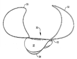
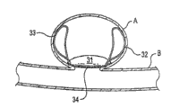
Figure 1A represents to be in the schematic front perspective view of amplification of an embodiment of the implantable locking device of deployed condition.
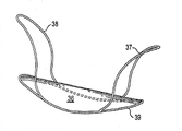
Figure 1B represents to be in the schematic front perspective view of amplification of another embodiment of the implantable locking device of deployed condition.
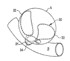
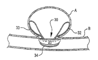
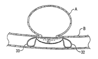
Fig. 1 C, 1D, 1E and 1F are schematically illustrated in Figure 1A of aneurysm site expansion and the locking device of Figure 1B.
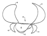
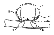
Fig. 2 A shows the schematic front perspective view of amplification of another the implantable locking device that is in deployed condition, and Fig. 2 B schematically implantable locking device of displayed map 2A launches at the vascular defect place.
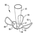
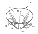
Fig. 3 A and 3B show the schematic front perspective view of the amplification of another implantable locking device, and the device of Fig. 3 A is in the part deployed condition, and the device of Fig. 3 B is in complete deployed condition.
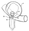
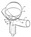
Fig. 4 A-4C schematically shows and is in part deployed condition and fully Fig. 3 A of deployed condition and the implantable locking device of Fig. 3 B.Fig. 4 A shows the implantable locking device that inserts in the aneurysm neck; Fig. 4 B is presented at the device (dotting) of Fig. 3 B that is in deployed condition in aneurysm and the blood vessel; And Fig. 4 C is presented at the device of Fig. 3 B that is in deployed condition in the aneurysm, and aneurysm and blood vessel illustrate with the cross section.
Fig. 5 shows the enclosed construction that comprises flexible sticking patch (patch), and this flexibility sticking patch has near a plurality of anchoring structures the circumference that is arranged on enclosed construction.
Fig. 6 A-6C shows the amplification perspective schematic view of the implantable device that is in deployed condition, and this implantable device has the neck linear element that has rock-steady structure.
Fig. 7 A shows the amplification schematic side elevation of another embodiment of the implantable device that is in feed status, this implantable device has the enclosed construction of being combined with anchoring structure, and Fig. 7 B shows the amplification schematic side elevation of another embodiment of the implantable device of the present invention that is in the part deployed condition.
Fig. 8 shows the amplification schematic side perspective view of the implantable device that is in deployed condition, and this implantable device has relative grappling pole.
Fig. 9 shows the amplification schematic side perspective view of another embodiment of the implantable device that is in deployed condition, and this implantable device has roughly spherical packaged unit.
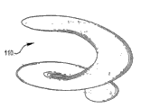
Figure 10 shows the amplification schematic side perspective view of another embodiment of the implantable device that is in deployed condition, and this implantable device has the bung flange structure.
Figure 11 is presented at the amplification schematic side elevation of the implantable device of the present invention in the induction system.
Figure 12 A-E shows for the enlarged diagram of placing the useful method of deploying of device of the present invention.
Detailed description of the Invention
Describe and illustrated implantable system of the present invention in detail about the application as the aneurysm locking device.Yet, it should be understood that these systems are not limited to this application, and can adapt to and use in conjunction with other vascular, tissue or air duct cavity, unusual etc. treatment and repairing.Similarly, the method that should understand for the applicant of correction of the defect and opening is not limited to system described herein.
Implantable locking device of the present invention roughly comprises the enclosed construction that strides across tissue or vascular defect placement and the anchoring structure that enclosed construction is located and is held in place.A plurality of alternatives and alternative construction are disclosed at this.(a plurality of) flexible sticking patch that adopts in enclosed construction disclosed herein or (a plurality of) film are made of flexible material usually, and this flexible material can be carried by conduit under the minor diameter feed status, and presents bigger size configurations under deployed condition.In one embodiment, this enclosed construction by such as the liquid of blood and body fluid basically the material of impermeable constitute.Alternatively, this enclosed construction can be made of following material, and this material can be by such as the semi-transparent mistake of the liquid of blood and body fluid or see through, and allows to pass the limited exchange of sticking patch or film at least.This enclosed construction can be used according to device have multiple structure, and can be roughly circle, ellipse, avette, triangle, polygon etc.
This enclosed construction is made of (multiple) material, and this material is biocompatible and Biostatic, and compressible, collapsible or can additionally be out of shape, and is used for presenting the minor diameter profile packing into or be mounted under the feed status of delivery conduit.The material that forms enclosed construction can comprise for example multiple natural polymerization material or synthetic polymeric material; Silicone material; Elastomeric material; Weave or non-woven textile material, such as Dacron
TMFluoropolymer is such as for example
Polytetrafluoroethylene (PTFE) material or for example
Deng expanded PTFE (ePTFE); Polymeric material, such as polyurethane, polyurethane/silicon resin composition and copolymer, etc.In another embodiment, enclosed construction can comprise metal material, and such as the film shape memorial alloy, thin film Nitinol for example is such as nitinol.The multiple rete and the film that comprise multiple composition and component can be provided.In certain embodiments, this enclosed construction is made of material flexibility and elastic, and with this enclosed construction be placed on wherein tissue or movement or the pollex of blood vessel roughly radially expand and shrink.
In certain embodiments, this enclosed construction comprises network structure, and this network structure has uniform or inhomogeneous structure at its surf zone.Usually, the enclosed construction with reticulated structure has meticulous network structure usually.In certain embodiments, this enclosed construction has the network structure that can radially expand.In other embodiments, have can be along the network structure of one or more axis expansion for this enclosed construction.
This enclosed construction can have surface texture porous or perforation at least a portion of its surf zone, hole is arranged as at surf zone basic porosity uniformly is provided, or hole is arranged as in the different surfaces zone of enclosed construction different porositys is provided.Average pore size can be on the surf zone of enclosed construction basically identical, perhaps can provide to have the hole that different size distributes.Usually, be suitable at the pore-size in about 0.5 micron to 200 microns scope.In one embodiment, provide such pore structure, it allows flow of liquid to cross this enclosed construction but eliminating comprises erythrocytic big protein and cell.Usually, average diameter will be got rid of big protein and cell less than about 10 microns hole, and allow fluid to penetrate and cross film simultaneously.But the layout formation rule of hole or irregular pattern, the structure of hole can be consistent or inconsistent, and can be roughly circle, ellipse, square etc.For example bigger porosity can be set in the circumference office of enclosed construction, this peripheral part after placing near to or in contact with organizing or blood vessel wall.
Alternatively or additionally, this enclosed construction can promote the surface treatment of cell attachment and growth on one or both sides.For example, in one embodiment, the material that forms enclosed construction has following surface structure, and this surface is configured to irregular or coarse, perhaps has the surface irregularity of the cell attachment that promotes material.In another embodiment, this enclosed construction can have three-dimensional structure, and this three-dimensional structure has the pit that adopts regular or irregular pattern, groove, passage etc., to promote cell attachment and endothelialization again.
Herein in more disclosed devices, the enclosed construction of implantable device and/or other member, comprise one or more anchoring structures, be constructed to or be treated to and promote cell inwardly to grow or adhere in folded-out position, perhaps comprise material or (multiple) material of promoting that cell is inwardly grown or adhered in folded-out position.Similarly, method of the present invention can be included in and place before the implantable device, introduces during placing implantable device and/or after placing implantable device and promote cell inwardly to grow and (multiple) preparation of endothelialization again in the device folded-out position.For example, for vascular applications, some use to wish promote blood vessels at the endothelialization again of position that can be by placing aneurysm that device of the present invention repairs or other vascular defect.Multiple material that can related use with method and system of the present invention discloses in 2004/0087988 and 2004/0193206 at United States Patent (USP) description, and above-mentioned patent disclosure is incorporated among the present invention by reference and all.
Can before installing expansion, during device launches or after the device expansion, apply multiple material, perhaps be associated with implantable device, inwardly grow with the promotion cell.Can be used for this purpose biocompatible material and comprise for example protein, such as collagen, fibrin, fibronectin, antibody, cytokine, somatomedin, enzyme etc.; Polysaccharide is such as heparin, chrondroitin; The cross-linked gel of biogenetic derivation; Nucleic acid; Poly-(.alpha.-hydroxy acid); RNA; DNA; Other nucleic acid; Polyester and poe are such as poly-Acetic acid, hydroxy-, bimol. cyclic ester, polyactide and polyactide-common-Acetic acid, hydroxy-, bimol. cyclic ester; The polylactone that comprises polycaprolactone; PPDO; Polyamino acid such as polylysine; Polybutylcyanoacrylate; Poly-(phosphazine); Poly-(phosphate ester); Polyesteramide; Polyacetals; Polyketals; The Merlon and the poly-orthocarbonic ester that comprise trimethylene carbonate; Degradable polyethylene; Poly-alkylene ethanedioic acid ester; Poly-alkylene succinate; Chitin; Chitan; Oxidized cellulose; Polyhydroxy-alkanoates, it comprises poly butyric ester, polyhydroxy valerate and copolymer thereof; The polymer of poly(ethylene oxide) and copolymer; The poly(ethylene oxide) that acrylic acid stops; Polyamide; Polyethylene; Polyacrylonitrile; Polyphosphazene; By the polyanhydride that the dicarboxylic acid monomer forms, it comprises unsaturated polyanhydride, poly-(amide anhydride), poly-(carboxylic acid amide esters) acid anhydride, the equal polyanhydride of aromatic-aliphatic, aromatic series polyanhydride, poly-(ester acid anhydride), fatty acid-based polyanhydride etc.; And other biocompatible polymeric material or generate polymeric material naturally, with and copolymer and terpolymer; The fragment of bioactive materials and the mixture of above-mentioned material.
But some biocompatible polymer are considered to bio-absorbable, and be fit to related use with apparatus and method of the present invention, this biocompatible polymer comprises polyactide, poly-Acetic acid, hydroxy-, bimol. cyclic ester, polyactide-altogether-and Acetic acid, hydroxy-, bimol. cyclic ester, polyanhydride, poly--the dioxy Ketohexamethylene of p-, trimethylene carbonate, polycaprolactone, polyhydroxy-alkanoates etc.Also can use and not think biodegradable biocompatible polymer usually, it comprises polyacrylate; Ethylene-vinyl acetate; Cellulose and cellulose derivative, it comprises acetylbutyrylcellulose and cellulose acetate propionate; Cellulose acetate and derivant thereof that acyl group substitutes; Not corrodible polyolefin; Polystyrene; Polrvinyl chloride; Polyvinyl fluoride; Polyethylene (imidazoles); Chlorosulfonated polyolefin; Poly(ethylene oxide); Polyethylene Glycol; Polyvinyl pyrrolidone; Polyurethane; Polysiloxanes; The mixture of the copolymer of above-mentioned material and terpolymer and above-mentioned material.Exemplary polymer is known in the art, and those skilled in the art will be appreciated that this polymer can not be listed at this too much.Therefore, this tabulation only is used for the illustrative purpose, and is not used in detailed purpose.
Non-cohesive material also can be used for closed system of the present invention.Suitable non-cohesive material comprises for example hormone and antitumor agent.The example of other biocompatible material that promotion combines with patient's vascular system for example comprises the mankind or the animal tissue that handled, and comprises for example cell or cell fragment; Artificial vascular tissue; Carcass material from bladder, stomach, liver; Hereditary material of nature source or synthetic source etc.
The synthetic of other type also can be associated with enclosed construction or (a plurality of) anchoring structure of forming closed system of the present invention.For example, hydrophilizing agent and/or water-repelling agent or binding agent can be arranged on the whole last or part of (a plurality of) structure.Similarly, comprise that anti-friction agent such as the fluoropolymer of PTFE can be arranged on (a plurality of) structure whole go up or a part on so that from delivery conduit or sheath, launch.Radio opaque markers or radiopaque mixture can be associated with certain structure or the part of apparatus structure, so that deployed device is accurately located, placed and monitors.For example, in one embodiment, radiopaque synthetic can be combined in the enclosed construction, perhaps as the coating on the enclosed construction.In yet another embodiment, certain therapeutic agent, antibacterial, coagulant, anticoagulant etc. can be associated with certain structure or the part of apparatus structure, perhaps can apply before implantable device launches, during implantable device launches or after the implantable device expansion.Appropriate formulation is known in the art, and uses in conjunction with the implantable device of other type.
Enclosed construction can comprise multilamellar, and can have multiple coating associated with it or other material, such as coherent substance or adhesion substance, and therapeutant, hydrophilic material or hydrophobic material, such as the expandable material of hydrogel, radiopaque labelling etc.For example, in one embodiment, expandable hydrogel can be arranged on enclosed construction under the deployed condition and/or anchoring structure in the face of or contact on the surface of aneurysmal inside.In another embodiment, be convenient to form the preparation of thromboembolism or thrombosis or preparation combination can be arranged on enclosed construction under the deployed condition and/or anchoring structure in the face of or contact on the surface of aneurysmal inside, to promote at the inner thromboembolism that forms of aneurysm.In yet another embodiment, reducing enclosed construction and/or the anchoring structure that the combination of thrombosis and the preparation that condenses or preparation can be arranged under the deployed condition faces or contacts on the surface of blood vessel or blood vessel wall, said preparation or preparation combination are such as heparin, tissue plasminogen activator (tPA), Abciximab etc.In yet another embodiment, the preparation or the preparation combination that prevent the inflammation at restenosis and/or minimizing position can be arranged on the surface of enclosed construction and/or anchoring structure, said preparation or preparation combination are such as Paclitaxel or derivant or analog, Sirolimus, chemical compound such as the anti-inflammatory of steroid, inhibin, ibuprofen etc.In yet another embodiment, radioactive synthetic can be associated with the surface of enclosed construction and/or anchoring structure, is used for the treatment of purpose or imaging purpose.
The film that forms enclosed construction can have continuous substantially surf zone, perhaps can have one or more openings or the line of rabbet joint, and it helps to place implantable device and maybe this device is installed on conduit or the induction system under feed status.This film by be shaped, bonding, stitching, embedding etc. are fixed on framework or the anchoring structure, this framework or anchoring structure preferably include the shape-changing material such as marmem.Some membrane materials also can be applied on framework or the anchoring structure or are applied to framework or anchoring structure by coating, dip-coating etc.
The framing component of supporting enclosed construction can be made of biocompatible shape-changing material, this framing component such as anchoring structure and reinforcement structure, and this biocompatible shape-changing material has superpower elasticity and/or shape memory characteristic, such as marmem.This shape-changing material changes shape in predictable mode when the deformation power that applies such as heat, electric current etc., to present its predetermined deployed condition.Active force for generation of deformation is generally variations in temperature, and this variations in temperature is for example introduced the body temperature environment by installing, heated this device and produce to device or by making electric current flow through conducting element by utilizing external heat mechanism to apply heat.The phase transition temperature that shape-memory material is heated to material or above after, the frame structure of this device and/or (a plurality of) anchoring structure present the structure of its predetermined large-size.
Has the nitinol of ultra-strong elasticity and shape memory characteristic for being used for the preferred shape memorial alloy of apparatus of the present invention.Framework and anchoring structure for example can be formed by solid silk, tubular filament, braided material etc., and/or can cut out from pipeline configuration or cylindrical structural.Framework and anchoring structure can be in conjunction with other materials, and can have between the frame structure of being arranged on and among coating or film.In one embodiment, framework and anchoring structure can utilize following sputtering technology known in the art to be formed by the film shape memorial alloy such as the film nitinol.
Implantable device usually utilizes to have the delivery conduit that promotes conduit or bar or special microtubular (being called " delivery conduit ") or utilizes the moving system with separating mechanism to be delivered to impact point.For example, in a system, this enclosed construction is mounted on the far-end of delivery conduit separably with little profile state, and covers and remain little profile state by contractile sheath.This delivery conduit can utilize conventional art to be positioned at the aneurysm neck place or be positioned in the aneurysm neck, and after jacket shrinkage, this enclosed construction presents its predetermined deployed condition and strides across aneurysm neck to be placed.More specifically, in first step, after the part of sheath is shunk, first anchoring structure is launched and orientates as near the tissue aneurysm neck that contacts or approach in aneurysm inside; In second step, enclosed construction or film stride across the aneurysm neck location and cover aneurysm neck substantially; After the contraction fully of sheath, second anchoring structure is launched and orientates as near the interior vessel that contacts or approach aneurysm neck.
Figure 1A shows the embodiment of locking device 30, and it comprises sticking patch or the enclosed construction 31 that is mounted on two anchoring structures 32,33 or is associated with two anchoring structures 32,33.The suitable material that is used for the structure of enclosed construction or film has above been described.Enclosed construction 31 is supported by frame structure 34, and this frame structure 34 is arranged in the circumference part of enclosed construction 31 at least, and is attached on the enclosed construction 31 by bonding, stitching etc.Frame structure 34 is installed on the wing anchoring structure 32,33 or with wing anchoring structure 32,33 and is correlated with.Frame structure 34 and anchoring structure 32,33 all preferably include the shape-changing material such as the nitinol material.
Anchoring structure 32,33 can comprise solid silk or tubular structure, perhaps can be by having braiding structure or other cancellated material forms.At least a portion that the structure of the anchoring structure 32,33 under the deployed condition is designed to anchoring structure 32,33 contacts the inwall of aneurysmal inwall or relevant blood vessel after launching.The structure of anchoring structure 32,33 can be circle, ellipse roughly or additionally forms curve construction, and perhaps anchoring structure 32,33 can form polygonal structure.In a preferred embodiment, shown in Figure 1A, anchoring structure 32,33 is oval-shaped curvilinear structures roughly, and it is bent outwardly to frame structure 34 from attached joint 35, inwardly returns towards ground each other at the place, end away from attached joint 35 then.
In the embodiment shown in Figure 1A, anchor ring 32,33 has roughly the same structure and roughly the same size, and roughly arranges relative to one another.In another embodiment, anchoring structure can have different structures and/or size.For example, in one embodiment, comparable another anchoring structure of anchoring structure is longer and/or wideer, and perhaps anchoring structure can have curve construction or the polygonal structure of different three-dimensionals.Though show two anchoring structures 32,33, will be appreciated that, other anchoring structure can be set.Anchoring structure preferably with respect to frame structure 34 and/or enclosed construction 31 roughly symmetrical manner arrange.
Figure 1B shows the similar locking device comprise the enclosed construction 36 with anchoring structure 37,38, and anchoring structure 37,38 is attached on the frame structure 39 or outstanding from frame structure 39 along the relative lateral margin of frame structure.Alternatively, this enclosed construction 36 can have opening or the line of rabbet joint that is arranged in the approximate centre zone.Anchoring structure 37,38 shown in Figure 1B is slight bending, and extends beyond the corresponding terminal part of frame structure and enclosed construction in its terminal part office.Enclosed construction among this embodiment and frame structure have the surf zone above the surf zone of aneurysm neck usually, and this anchoring structure is positioned at aneurysm inside usually after placing this device.In this structure, this anchoring structure applies the downward power of side direction at enclosed construction, so that enclosed construction roughly meets blood vessel wall in the profile at aneurysm site place, thereby with respect to the sealing of the stream in vascular aneurysm neck, and in aneurysm site place reconstruction blood vessel wall.
Fig. 1 C-1F is shown schematically in Figure 1A of aneurysm site expansion and the locking device of Figure 1B.Protuberance among the blood vessel B forms aneurysm A.Shown in Fig. 1 C and 1D, in one embodiment, when locking device 30 strides across the tumor neck of aneurysm A and launches in aneurysm A, enclosed construction 31 is orientated as and is covered aneurysmal opening, and anchoring structure 32 and 33 to remain on aneurysm inner and contact internal arteries tumor wall along at least a portion surf zone of internal arteries tumor wall.Adopt this mode, enclosed construction 31 and frame part 34 stride across the aneurysm opening and are supported and are resisted against on the aneurysm neck from the aneurysm external bias.In the embodiment shown in Fig. 1 C and Fig. 1 D, enclosed construction 31 and frame part 34 launch in the outside of aneurysmal inner space.In the alternative shown in Fig. 1 E, enclosed construction 31 and frame part 34 stride across the aneurysm opening and are supported and lean against on the aneurysm neck partially from aneurysm inside.
Fig. 1 F shows optional development system and method, wherein, locking device with at least two anchoring structures expands into and makes enclosed construction 31 orientate the aneurysmal opening of covering as, and anchoring structure 32,33 is positioned near the outside and interior vessel of contact aneurysm of aneurysm.In this embodiment, anchoring structure 32,33 can set near the vascular internal diameter that is of a size of and is configured to aneurysm neck usually is complementary, and makes that anchoring structure contacts blood vessel wall in a substantially continuous manner after launching, and does not make blood vessel wall distortion or expansion in the aneurysm zone.In these all embodiment, after placing locking device, this enclosed construction covers aneurysm neck substantially repairing vascular defect effectively, and this anchoring structure basically with the interference of vascular stream.
Fig. 2 A shows another locking device 40 comprise enclosed construction 41, and this enclosed construction 41 is supported by frame structure 42, and is installed on grappling 43,44,45 and 46 or associated.The characteristic of enclosed construction 41 and structure are roughly same as described above.Enclosed construction 41 is preferably supported by frame structure 42, and this frame structure 42 is arranged at least in the peripheral part of structure 41 and by bonding, stitching etc. and is attached on the structure 41.Frame structure 42 is mounted on two pairs of wing anchoring structures 43,44 and 45,46 or is associated.The shape-changing material that frame structure 42 and anchoring structure 43,44,45 and 46 preferably include such as the nitinol material, and can comprise solid silk or tubular structure perhaps can be by having braiding structure or other cancellated material forms.
Anchoring structure 43,44,45 and 46 structures under deployed condition are designed to anchoring structure 43,44, and at least a portion of each anchoring structure in 45 and 46 contacts the inwall of aneurysmal inwall or relevant blood vessel after launching.Anchoring structure 43,44,45 and 46 structures under deployed condition can be circle, ellipse roughly or additionally form curve construction, perhaps can form polygonal structure.In the preferred embodiment shown in Fig. 2 A, anchoring structure 43,44,45 and 46 is oval-shaped curvilinear structures roughly, it is bent outwardly to frame structure 42 from attached joint, inwardly returns towards ground each other at the place, end away from frame structure 42 then.In the embodiment shown in Fig. 2 A, anchor ring 43,44,45 and 46 form roughly the same structure and roughly the same size.Anchor ring 43 and 46 is respectively with the substantial mirror images direction location with respect to anchor ring 44 and 45.Similarly, anchor ring 43 and 44 is respectively with the substantial mirror images direction location with respect to anchor ring 46 and 45.In alternative, anchor ring 43,44, structure and/or the size of each anchor ring in 45 and 46 can change, anchor ring 43,44, structure and/or the size of each anchor ring in 45 and 46 can be inequality.Though show two pairs of roughly relative anchoring structures, will be appreciated that, other anchoring structure or paired relative anchoring structure can be set.Anchoring structure preferably with respect to frame structure 42 and/or enclosed construction 41 roughly symmetrical manner arrange.
The locking device of Fig. 2 B displayed map 2A shown type, it expands into and makes sticking patch 41 orientate the aneurysmal opening of covering as, thereby two anchoring structures are positioned at least a portion of the inner contact of aneurysm aneurysm wall, thereby and two anchoring structures be positioned near the interior vessel of the outside contact of aneurysm aneurysm.The interior expansion of tumor neck that the method for utilizing locking device shown in Figure 2 to repair vascular roughly is included in aneurysm A for example comprises anchor ring 43,46 first anchoring structure, and anchor ring 43,46 is orientated as near to or in contact with near the internal arteries tumor wall aneurysm neck; Stride across aneurysm neck and launch enclosed construction 41, with basic covering aneurysm neck; And at outside second anchoring structure that launches for example to comprise anchor ring 44,45 of aneurysm neck, and anchor ring 44,45 orientated as near to or in contact with near the interior vessel aneurysm neck.
The optional embodiment of aneurysm locking device is shown as in Fig. 3 A and is in the part deployed condition, is shown as to be in complete deployed condition in Fig. 3 B.In this embodiment, locking device 50 comprises taper enclosed construction 51, this taper enclosed construction 51 has the roughly frusto-conical configuration that is connected on the closing membrane 52, and have and comprise a plurality of positioning elements 53,54,55 and 56 anchoring structure, this closing membrane 52 has the characteristic of above-mentioned enclosed construction.
Taper enclosed construction 51 preferably includes loose structure or the network structure that is made of the deformation metal material, this deformation metal material provides the minor diameter structure of little profile under feed status, and during launching, extend to the deployed condition of expansion, at least a portion of this deformation metal material contact aneurysm inwall in this state.This loose structure or network structure can have usually big or common little space between structure, this space and structure can be symmetry or asymmetric, and can be general curved or substantial linear and angled.The cancellated adequate types of expansion is known, and for example uses with various stents.Taper enclosed construction 51 can be covered by flexible fabric or membrane material at least in part or be associated, perhaps can be relevant with the fibrous material of other type, this flexible fabric or membrane material are biocompatible and Biostatic, such as silicone material, PFTE material, Dacron
TMDeng.
Taper enclosed construction 51 can be connected at minor diameter base portion 57 places on the closing membrane 52 or be associated.Enclosed construction 51 can have roughly the circumference corresponding to the structure of minor diameter base portion 57, and perhaps alternatively, the circumference of this enclosed construction 51 can have than the bigger shaping structure of the structure of minor diameter base portion 57 or different shaping structure with it.For example, in one embodiment, enclosed construction 51 is installed near on the frame structure 58 of its circumference or associated, and is mounted at the inner side place of its circumference on the base portion 57 or associated.
The positioning element 53,54,55 and 56 of locking device 50 can have the circulus that is similar to above-mentioned anchoring structure.Alternatively, positioning element 53,54,55 and 56 can comprise solid metal structure, netted discontinuous construction or therein flexible material be installed on the frame structure that limits this positioning element or structure associated therewith.Two or more positioning elements can with respect to enclosed construction 51 roughly the layout of radial symmetric arrange and arrange.In another embodiment, the discontinuous network structure of taper can be used as anchoring structure, and has the structure more shallow than the structure of taper enclosed construction 51.
Fig. 4 A-4C is presented at during the expansion and is in the locking device 50 that expands in aneurysm and stride across aneurysm deployed condition afterwards.The locking device 50 in the aneurysm A is inserted in Fig. 4 A display part.When first anchoring structure by aneurysm neck and when being positioned in the aneurysm, and film 52 strides across aneurysm neck and extends and the base closed aneurysm neck, launches taper enclosed construction 51. Positioning element 53,54,55 and 56 launch and are positioned at the outside of aneurysm neck after launching, and near at least a portion of the blood vessel wall of contact aneurysm neck.Therefore, place this closed system and will repair blood vessel wall, and with vascular prosthesis to normal and healthy substantially structure.
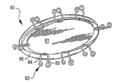
Fig. 5 shows another embodiment of the implantable device 60 that comprises flexible enclosed construction 61, and this flexibility enclosed construction 61 has on the periphery that is installed in enclosed construction or remains near a plurality of anchoring members 62 of this periphery.As shown in the figure, anchoring members 62 has at least two isolated arms 63,64, and can be installed in inner surface or the outer surface of enclosed construction 61, perhaps can alternatively pass enclosed construction and install, and relative arm 63,64 is from apparent surface's extension of enclosed construction 61.Arm 63,64 can be positioned on the enclosed construction, makes the outer peripheral edges 65 of structure 61 be arranged in the outside of the junction of relative arm 63,64 and enclosed construction 61.
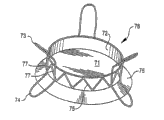
Fig. 6 A-6C shows optional locking device.Closed system 70 shown in Fig. 6 A comprises center enclosed construction 71, and it has neck shape structure 72 and a plurality of anchoring structure 73 and 74 of reinforcement.Alternatively, enclosed construction 71 can have opening or the line of rabbet joint that is arranged in the approximate centre zone.The neck shape structure of strengthening 72 can or constitute, and be installed near the circumference of enclosed construction 71 independently with enclosed construction 7 one.Neck shape structure 72 comprises strengthening part 75 and flexible membrane parts.In a word, the neck shape structure of reinforcement forms cylindrical, avette etc. the upright thimble structure can be roughly, and intention is projected in the aneurysmal inside being placed on the aneurysm neck place after and relatively vascular seal the tumor neck region.This strengthening part 75 can with shown in the zigzag pattern setting, the another kind of graphic setting of structure support perhaps is provided for upright neck shape structure with strengthening part 75.Though it is outstanding that the neck shape structure of strengthening 72 is depicted as along the direction on the plane that is basically perpendicular to enclosed construction 71, but will be appreciated that, according to desired application and expectation by the structure of inaccessible body structure, the neck shape structure 72 of reinforcement can acutangulate along the planar shaped with respect to enclosed construction 71 or the direction at obtuse angle outstanding.
Anchoring structure 73,74 preferably is made of common rigid material, and this rigid material is preferably the shape-memory material such as Nitinol.In the embodiment shown in Fig. 6 A, anchoring structure 73 and 74 outstanding at the opposite side on the plane of enclosed construction 71, and connected by the structural support member 77 of centre.Anchoring structure can be whole and provides as single structure, perhaps can provide discretely and the anchoring structure of location relatively.Anchoring structure 73,74 is being constructed for having the general triangular that has fillet shown in Fig. 6 A.In the optional embodiment of the locking device 78 shown in Fig. 6 B, anchoring structure has structure more circular, the folder shape.Anchoring structure can have multiple size and structure, and can have usually wide or common narrow profile.For some application, anchoring structure can have reticulated structure or vesicular structure.Though show three groups of anchoring structures, will be appreciated that, still less or more anchoring structure can be set, and anchoring structure is usually to arrange with respect to the mode of center sticking patch radial symmetric.
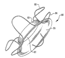
Fig. 6 C shows the similar closed system 80 that comprises center enclosed construction 81, and this center enclosed construction 81 has collar zone 82 and the horn-like skirt section 83 of substantial cylindrical.Boundary between collar zone 82 and the horn-like skirt section 83 be general curved with continuous.Provide reinforcement by relative grappling arm 84,85, this grappling arm 84,85 is staggered toward each other and with the mode arrangement of radial symmetric roughly.
Fig. 7 A shows another embodiment (Fig. 7 A) of the locking device 120 of the feed status that is in minor diameter, and Fig. 7 B demonstration is in optional locking device 130 larger-diameter, basic deployed condition.Locking device 120 comprises first group of anchoring structure 122 and second group of anchoring structure 124, and this first group and second group of anchoring structure 122 and 124 are outstanding and be substantially transverse to enclosed construction 128 from the opposite side of middle thimble structure 126.Anchoring structure 122 and 124 preferably includes shape-changing material, and forms the structure of substantially cylindrical under the feed status shown in Fig. 7 A.These anchoring structures (122,124) are crooked radially outwardly during launching, to form the circulus of basic circumference under deployed condition.
Anchoring structure 122 and 124 is preferably AT substantially, and is configured to reduce to greatest extent to the wound of anchoring structure 122 with 124 tissues that contact under deployed condition.In one embodiment, anchoring structure 122 and 124 has structure and the cross-sectional configuration of general planar.In the embodiment shown in Fig. 7 A, anchoring structure (122,124) has essentially identical structure and size, and is outstanding at the opposite side of intermediate collar structure, and arranges with basic structure staggered or that depart from.Under deployed condition, anchoring structure 122,124 is the not lap of the tissue of contact on the opposite side of the defective of sealing usually.This layout is generally AT, and promote with keep tissue survival power and the zone that is contacted by locking device in blood flow.The distally pad 123 that enlarges can be relevant with anchoring structure 122 and 124 respectively with nearside pad 125, with the location of promotion locking device and expansion and the contact area of larger diameter is provided in the contact area of organizing.
Though anchoring structure 122 and 124 is depicted as total length greater than the smooth silk structure of the general triangular of the length of intermediate collar structure, will be appreciated that, can use alternative structure.Anchoring structure can be in conjunction with other reinforcement structure or pressure distribution structure, and it can adopt other structure or the form of surf zone.Alternatively or extraly, the film such as the film that is used for constituting enclosed construction can be used for one or more anchoring structures.
One or more radio opaque markers preferably are arranged near the end away from the intermediate collar structure of anchoring structure 122,124, and this end is corresponding to far-end and the near-end of the implantable device under feed status.For example, pad 123 and 125 can have or comprise radiopaque labelling or associated, thus during launching and after launching the terminal of two groups of anchoring structures of labelling.Can use suitable radiopaque material, such as tantalum, gold, silver, barium, platinum, tungsten etc.Discrete radiopaque labelling for example can be relevant with anchoring structure by gluing, adhesion, crimping, welding, laser weld etc.
Fig. 7 B shows a part that is in another locking device 130 of the present invention under the part deployed condition.Locking device 130 comprises first group of anchoring structure 132 and second group of anchoring structure 134, and enclosed construction 138 is given prominence to and be substantially transverse to its opposite side from middle thimble structure 136.Anchoring structure 132 and 134 preferably is made of shape-changing material, this shape-changing material forms the structure (shown in Fig. 7 A) of substantially cylindrical under feed status, and during launching, change structure and make anchoring structure 132 to provide, 134 form the larger-diameter structure of the circulus of basic circumference under expansion or part deployed condition, shown in Fig. 7 B.Anchoring structure 132,134 can be substantially shown in Fig. 7 B under deployed condition, and perhaps according to type and the structure of the tissue defects of being repaired by implantable device, this anchoring structure 132,134 can be further crooked towards the centrage that installs under complete deployed condition.Similarly, intermediate collar structure 136 can have upright substantially cylindrical structure under the deployed condition fully, shown in Fig. 7 B, perhaps the intermediate collar structure is can be with anchoring structure angled or circumferential other places crooked, contacts near the structural structure that is clamped in securely near the tissue the defective and with this device the defective to provide not have the wound mode.According to the type of the size of defective, tissue to be repaired and thickness etc., can be arranged on the device construction various bendings and/or curve under the deployed condition.
Preferably, anchoring structure 132 and 134 is AT substantially, and is configured to farthest reduce to the wound of anchoring structure 132 with 134 tissues that contact under deployed condition.In one embodiment, anchoring structure 132 and 134 has structure substantial cylindrical or tubulose and cross-sectional configuration.In the part deployment configuration shown in Fig. 7 B, anchoring structure 132,134 is outstanding at the opposite side of intermediate collar structure 136, and the structure with basic aligning is arranged, thus, when after the impact point place launches, relative anchoring structure is near the relative tissue surface of essentially identical position contact defective.Anchoring structure 132,134 distal terminus forms big surf zone usually, this surf zone stops with blunt usually structure, so that AT substantially anchoring structure to be provided, this anchoring structure contact tissue to be striding across defective and locate definitely and to keep this enclosed construction, and do not damage the tissue that this anchoring structure contacts.
Though anchoring structure 132 and 134 is depicted as total length greater than the silk structure of the general triangular of the length of intermediate collar structure, will be appreciated that, can use optional structure.Anchoring structure can have other reinforcement structure or pressure distribution structure, and it can adopt other structure or the form of surf zone.Alternatively or extraly, the film such as the film that is used for constituting enclosed construction can be used for one or more anchoring structures.
One or more radio opaque markers preferably are arranged near the end away from the intermediate collar structure of anchoring structure 132,134, and this end is corresponding to far-end and the near-end of the implantable device under feed status.For example, relevant with the part of anchoring structure by making the radiopaque material, the radiopaque labelling can be set.Can use suitable radiopaque material, such as tantalum, gold, silver, barium, platinum, tungsten etc.The radiopaque labelling for example can be relevant with anchoring structure by gluing, adhesion, crimping, welding, laser weld etc.Be with 133 and 135 for example can have or comprise radiopaque labelling or associated, therefore the terminal of two groups of anchoring structures of labelling during launching and after launching.
Intermediate collar structure 136 comprises the reinforcement structure that is formed by rib 137, and this rib 127 forms the reinforcement structure of substantial cylindrical, and to provide than the common finer and close structure of the structure of anchoring structure 132,134.Rib 137 forms the structure of roughly intersecting, and can be bonded on the membrane structure or associated, this membrane structure be flexible and can with the basic common extension of thimble structure.This thimble structure can form roughly upright cylindrical structural under deployed condition, perhaps as mentioned above, thimble structure and rib can be angled or with outside circumferential configuration bending.Transverse seal structure 138 can install or be bonded in intermediate collar structure 136 and/or with membrane structure that thimble structure is associated on or the membrane structure that is formed with intermediate collar structure 136 and/or is associated with thimble structure, and can be continuous substantially or can have for the line of rabbet joint or opening by seal wire or other apparatus.One or more radio opaque markers are preferably relevant with thimble structure 136 and/or transverse seal structure 138.
Fig. 8 represents another embodiment of locking device 90, wherein the locking device 91 of Kuo Daing provides inaccessible surface in heart zone therein, and be provided for the substrate of attached reinforcement structure, this reinforcement structure is included in a plurality of grappling poles 92 and 93 that form petal-like circular pattern under the deployed condition, and relative pole 92 and 93 is the structure of base image.Pole 92,93 is connected to each other by intermediate structure 94.Strengthen the structure that structure can form single interconnection, perhaps a plurality of independent structures of attachable or installation coordinated with each other.
When locking device 90 launches after the device that will be in the minor diameter feed status is delivered to the tumor neck of opening, grappling pole 92 at first is expanded to the inside of opening and orientates contact as or near aneurysmal inwall, and intermediate structure 94 roughly is positioned at the tumor neck place of opening.When further expansion, grappling pole 93 is launched and near the interior vessel of the contact aneurysm opening, and enclosed construction 91 is pulled by opening mutually from the vascular direction.In this embodiment, locking device 91 can be used for the opening that obturation has irregular structure.
Fig. 9 shows another embodiment of the locking device 100 under the deployed condition that is in expansion.Locking device 100 comprises the conical or spherical structure 101 of general curved, and this structure 101 can for example be formed by the film shape memorial alloy such as Nitinol.Warp architecture 101 stops at the smaller diameter end place of enclosed construction (not shown), and has opening in larger diameter end.In the embodiment shown in fig. 8, warp architecture 101 comprises membranous wall 102 or a plurality of lamina membranacea of being strengthened by a plurality of ribs 103.Rib 103 is usually with the mode arrangement of radial symmetric, and can arrange still less or more rib.In another embodiment, membranous wall 102 can be strengthened by the frame structure of network structure or other type.
Locking device 100 also comprises the maintenance structure 104 that at least one is used to stride across the opening location and keeps this device 100.Keep structure 104 can adopt the form of the band of bending or coiling, perhaps can form the structure of petal-like or ring-type, and a plurality of maintenance structures 104 can be set.During device 100 expansion, chondritic 101 is positioned in the open interior expansion, and (a plurality of) keep structure 104 still in the outside of the tumor neck of opening, and by near the wall of the structure of contact opening device 100 is anchored in the opening.
Figure 10 shows another embodiment of the locking device 110 with spiral structure.For example, frame structure can be arranged on inner boundary and the external boundary place of helical structure, and film can be mounted on the frame structure or with frame structure and forms.In one embodiment, helical structure has smaller diameter end and larger diameter end.In another embodiment, locking device of the present invention can comprise relative Double-spiral bung flange structure.In this embodiment, provide relative bung flange structure, its be included in its small diameter portion in the middle of the place connect and two bung flanges of radial expansion (adopting rising/drop mode) in opposite direction.
Bung flange is strengthened structure can comprise the biocompatible material that embeds or be mounted to the nitinol wires of the membrane material that forms enclosed construction or be preferably shape-changing material.The size of film makes and invests overlapping ring formation superposition boundary when being in the coiling structure that bung flange is strengthened structural film.Locking device 110 expands into and makes the larger diameter end of terminal of a bung flange be positioned at the inside for the treatment of inaccessible opening, and should spiral-shapedly recline opening formation and change tightly when device launches.Two relative bung flange structures of this device are orientated the tumor neck that strides across opening as in this small diameter portion of meeting, and this relative bung flange is deployed near the wall of the regional interior and structure (such as blood vessel) of contact opening of opening outside.
As mentioned above, enclosed construction and the film for closed system disclosed herein can be formed by the film shape memorial alloy such as the thin film nitinol.The thickness that is used for the thin film nitinol of film of the present invention and enclosed construction is preferably about 0.5-100 micron, about 2-50 micron more preferably, and can be formed by each titanium and nickel between 45-55% of composition.
For example, can utilize United States Patent (USP) 6,533,905 described sputtering technologies prepare the thin film nitinol, thereby the open of this patent is incorporated among the present invention by reference and all.This technology can adopt the core (mandrel) that is formed by steel, glass, silicon etc., but it has the skin of the etching of exposure, and the thin layer sputtering sedimentation of nitinol is on this skin.After sputtering sedimentation, under annealed condition, the thin layer that is formed on the nitinol on the core is heated, and for example by core and attached thin layer are exposed to etchant and the thin film of gained is discharged from core.By form the barrier layer comprise opening pattern at annealing thin film, the thin film that covers is exposed to solvent in order to form window corresponding to opening pattern, and removes this barrier layer, can in the thin film nitinol, form window or little opening or hole.Structural member can be positioned on the core before the sputtering sedimentation of nitinol, so that thin film directly is attached on the structural member.
Being used for the framework of locking device or support unit and anchoring members for example can be from such as cutting out or etch the pipe of the film shape memorial alloy of thin film Ti-Ni alloy (being nitinol) or the cylinder.The technology that is used for the etched film marmem is known in the art.In one embodiment, for example, as people such as Gupta (SMST-2003:Proc.Intl.Conf.Shape Memory Superelastic Technol., (Pacific Grove, CA) eds.A.R.Pelton﹠amp; T.Duerig, p.639,2003) described, can prepare light-wall pipe.In brief, plural layers nitinol and expendable material (such as chromium) continuously sputtering sedimentation on smooth substrate surface, wherein first sedimentary deposit is formed by chromium, two layers that deposit subsequently of nitinol are separated by the second layer of chromium, and this smooth substrate surface is such as silicon chip polishing and oxidation.The thickness of this nitinol layer can be 1 to 40 micron, and the thickness of chromium layer can be about 500 dusts.Adopt two optical mask plates (photomask) (being called mask 1 and mask 2), mask has the predetermined pattern design of the size and dimension of definite resulting structures, and the structure of this gained is cylinder or pipe in this case.Mask 1 comprises that mask 2 comprises the design that makes the nitinol layer patternization for the design that makes the second chromium layer patternization at wafer.The MEMS technology of use standard makes thin film nitinol and chromium layer patternization.After being deposited upon thin film nitinol and chromium on the wafer, by wafer being immersed in the chromium etchant to dissolve all chromium layers, thereby between the first nitinol layer and the second nitinol layer, form recess (pocket), so remove multi-layer film structure from wafer.By the recess between two nitinol layers of tight fit core insertion that will be for example be formed by rustless steel and with 500 ℃ this structure is heat-treated in a vacuum, the membrane structure that will have the roughly release of rectangular shape changes three-dimensional cylinder into.Window with all desired sizes, shape and pattern can utilize the photoetching technique of standard to be formed in the nitinol layer.
On the other hand, implantable system disclosed herein comprises the locking device with device silk, and this device silk is connected to implantable device separably with separating joint and carries on silk/promotion silk.Device silk becomes integral body usually with implantable device, perhaps is attached on the implantable device at its far-end by separating joint, and for the desired locations that by the navigation that utilizes guiding catheter implantable device is delivered in the body.Suitable device silk, separating joint and conveying silk/promotion silk is known in the art, and can be used for locking device of the present invention.It is known in the art can be used for this device silk and carrying the material of silk.
Closed system of the present invention is used for repairing such as aneurysmal vascular defect and other physiological defect or the cavity that are formed on inner chamber, tissue etc.Method and system of the present invention utilizes the intracavity technology of minimally-invasive to repair and rebuilds internal chamber wall or tissue defects, and does not need invasive surgical operation.Conveying and expansion operation are direct usually works as, and still less more consuming time than many optional operations, reduces the risk of complication thus.
Figure 11 shows that being used for navigating to target repairs point and repair the implantable device of the present invention that is loaded in delivery conduit that the some place launches at target, and Figure 12 A-E shows exemplary conveying and method of deploying.Induction system 140 comprises delivery conduit 142, but it has suitable dimensions, flexibility and promotion, is used for navigating to the target repairing point of expectation, such as the aneurysm or the cavity that are formed in the blood vessel.Comprise navigation by the embodiment of (a plurality of) little inner chamber and/or tortuous passageway for the conveying that arrives such as the aneurysmal target point of delivery of neural blood vessel, delivery conduit 142 can comprise the microtubular with minor diameter and common high flexibility.(a plurality of) distally segmentation of delivery conduit for example comparable nearside segmentation is more soft.Multiple delivery conduit is known in the art, and is suitable for for induction system of the present invention.
Repair apparatus 144 can be any repair apparatus described here and/or the locking device with two groups of relative anchoring structures, and preferably is preloaded in the far-end 141 of delivery conduit 142 with the minor diameter feed status.When repair apparatus 144 is positioned in the delivery conduit 142 in order to carry, the far-end 145 of repair apparatus 144 is preferably corresponding to anchoring structure, this anchoring structure intention is placed on the inwall place of aneurysm to be repaired or cavity, perhaps is placed on internal chamber wall or the cavity surface place relative with inwall with respect to transfer passage.One or more radio opaque markers 146 can be arranged on repair apparatus 144 far-end 145 places or near.When repair apparatus 144 is positioned in the delivery conduit 142 in order to carry, the near-end 147 of repair apparatus 144 is preferably corresponding to anchoring structure, this anchoring structure intention is placed near the blood vessel wall place of the tumor neck of aneurysm to be repaired or cavity, perhaps is placed on inside internal chamber wall or cavity surface place with respect to transfer passage.One or more radio opaque markers 148 can be arranged on repair apparatus 144 near-end 147 places or near.Additionally or alternatively, repair apparatus 144 can have near the radiopaque labelling the central part of device, and this central part is roughly corresponding to the enclosed construction 149 of device.Additionally or alternatively, it is relevant with delivery conduit 142 that the radiopaque labelling can be set to, mark position corresponds respectively to extremity and the proximal portion of repair apparatus 144.
Induction system shown in Figure 11 and Figure 12 A-E is used for the guiding of repair apparatus 144 and seal wire 150 and the impeller 152 of location, and this impeller 152 has guidewire lumen and orientates as for the proximal portion 147 of contact repair apparatus 144 and with respect to delivery conduit 142 and move repair apparatus 144.Suitable seal wire and impeller are known in the art, and can be used for carrying repair apparatus of the present invention and locking device.
Therefore, the method that is used for repairing physiological defect or sealing opening or cavity 160 comprises that the repair apparatus 144 that utilizes technology that nothing is invaded or that minimum is invaded will be in the minor diameter feed status navigates to target at seal wire 150 and repairs point, and will be positioned at opening part to be repaired corresponding to the far-end of the repair apparatus 144 of first anchoring structure 145 or be positioned in this opening, shown in Figure 12 A.Alternatively, the radiopaque labelling that can be associated with intermediate collar or enclosed construction 149 by the opening location that strides across aneurysm in the blood vessel 170 or defective 160, location repair apparatus 144.Then, by the far-end of repair apparatus 144 being released from delivery conduit 142 and/or delivery conduit 142 being extracted out first group of anchoring structure orientated as near to or in contact with near the internal arteries tumor wall the tumor neck, expansion generally includes first anchoring structure of a series of grappling arms 145, shown in Figure 12 B.After launching, first group of grappling arm 145 expanded circumferentially and opened, wherein anchoring structure is orientated contact as or is approached the relative blemish surface of observing from transfer passage of the defective with to be repaired, and perhaps is positioned on the opposite side of the defective to be repaired of observing from transfer passage.Between expansion and fixation phase, can monitor the radiopaque labelling 146 that is arranged on first anchoring structure, to guarantee correct and AT location.
After first anchoring structure launched, the mid portion that comprises the repair apparatus of enclosed construction 149 expanded into and roughly strides across opening to be repaired and inaccessible defective opening, shown in Figure 12 C.After the enclosed construction 149, enclosed construction is opened or is expanded with this opening of basic covering in the middle of launching.In this state, first group of grappling arm 145 contacts or approaches very much a near side of the aneurysm inwall opening, and this enclosed construction 149 covers cavity openings.Then, extract out by the conduit of the portions of proximal of repair apparatus being released from delivery conduit 142 or will being associated with locking device, the portions of proximal of the repair apparatus of the radiopaque labelling 148 that comprises second anchoring structure 147 and be associated is launched, shown in Figure 12 D.After launching second anchoring structure, the grappling arm 147 of second anchoring structure is outwards expanded and is opened, and orientates contact as or approach the blemish surface that limits or form the part of transfer passage.At this moment, locking device 144 launches securely, and seal wire 150 is retracted in the delivery conduit 142.Induction system 140 is return from this position, and this locking device repairs this opening effectively, shown in Figure 12 E.
Therefore, by enclosed construction being installed as basic covering opening, and stride across opening with enclosed construction supporting and remain on the appropriate location, and anchoring structure is positioned on two apparent surfaces of near the defective inner chamber or tissue, method and system of the present invention is repair tissue defective or opening effectively.The regrowth subsequently of the cell in this device put area and the endothelialization again of tissue will recovery organization functions and correction of the defect effectively effectively.The radiopaque labelling is preferably used for launching and locating this device, and is used in the position of the various time supervision devices after placing.
Though in above-mentioned description, describe the present invention about some preferred embodiment of the present invention, but the many details that propose only for illustrative purposes, it will be apparent for a person skilled in the art that, the present invention allows various changes and improvements and other embodiment, and can change some details described here significantly and do not break away from essence spirit of the present invention and scope.
All patent documentations that this description is quoted are incorporated among the present invention by reference and all with open.
Claims (10)
1. one kind is used for repairing the opening of destination organization defective or the implantable device of cavity, described implantable device can be adjusted to deployed condition from feed status, described implantable device presents the structure of little usually diameter under described feed status, described implantable device presents the structure of bigger diameter under described deployed condition, and described implantable device comprises:
Enclosed construction, its size are set to cover substantially described opening or cavity when described device is in described deployed condition; With
When described device is in described feed status, first anchoring structure that extends along first direction from described enclosed construction and second anchoring structure that extends from described enclosed construction along roughly opposite second direction, when described device is in described deployed condition, described first anchoring structure and described second anchoring structure form the roughly structure of circumference, and the structure of described roughly circumference has the diameter greater than described enclosed construction.
2. implantable device according to claim 1 is characterized in that, described implantable device also comprise with described first anchoring structure and described second anchoring structure at least one radiopaque labelling of at least one structurally associated connection.
3. implantable device according to claim 2 is characterized in that, described implantable device comprise with described first anchoring structure and described second anchoring structure at least one radiopaque labelling of each structurally associated connection.
4. implantable device according to claim 1 is characterized in that, described implantable device also comprises the radiopaque labelling that is positioned at described first anchoring structure and described second anchoring structure centre.
5. implantable device according to claim 1 is characterized in that, described implantable device also comprises the radiopaque labelling that is associated with described enclosed construction.
6. according to each the described implantable device among the claim 2-5, it is characterized in that described radiopaque labelling comprises selected composition in the group that is grouped into by following one-tenth: tantalum, gold, silver, barium, platinum, tungsten and combination thereof.
7. implantable device according to claim 1 is characterized in that, described enclosed construction has continuous substantially inaccessible surf zone.
8. implantable device according to claim 1 is characterized in that, described enclosed construction has is convenient at least one opening that other device passes through.
9. implantable device according to claim 1 is characterized in that, described enclosed construction has structure and the mobile radial compliance that is enough to imitate described destination organization.
10. implantable device according to claim 1, it is characterized in that described enclosed construction comprises selected material in the group of being made up of following material: silicone material, elastomeric material, Woven fabric and supatex fabric, fluorine-containing synthetic, macromolecular material, polyurethane material, metal material and combination thereof.
Applications Claiming Priority (10)
| Application Number | Priority Date | Filing Date | Title |
|---|---|---|---|
| US72805205P | 2005-10-19 | 2005-10-19 | |
| US60/728,052 | 2005-10-19 | ||
| US11/324,827 | 2006-01-03 | ||
| US11/324,827 US8545530B2 (en) | 2005-10-19 | 2006-01-03 | Implantable aneurysm closure systems and methods |
| US74740006P | 2006-05-16 | 2006-05-16 | |
| US60/747,400 | 2006-05-16 | ||
| US80320006P | 2006-05-25 | 2006-05-25 | |
| US60/803,200 | 2006-05-25 | ||
| US82373006P | 2006-08-28 | 2006-08-28 | |
| US60/823,730 | 2006-08-28 |
Related Parent Applications (1)
| Application Number | Title | Priority Date | Filing Date |
|---|---|---|---|
| CN2006800476261A Division CN101489492B (en) | 2005-10-19 | 2006-10-18 | Methods and systems for endovascularly clipping and repairing lumen and tissue defects |
Publications (1)
| Publication Number | Publication Date |
|---|---|
| CN103230290A true CN103230290A (en) | 2013-08-07 |
Family
ID=48878414
Family Applications (2)
| Application Number | Title | Priority Date | Filing Date |
|---|---|---|---|
| CN 201310106823 Pending CN103230290A (en) | 2005-10-19 | 2006-10-18 | Method and system for clamping and mending inner cavity and tissue defects in vessel |
| CN201310108702.7A Expired - Fee Related CN103381101B (en) | 2005-10-19 | 2006-10-18 | For the method and system of clamping and repairing lumen and tissue defects in vascular |
Family Applications After (1)
| Application Number | Title | Priority Date | Filing Date |
|---|---|---|---|
| CN201310108702.7A Expired - Fee Related CN103381101B (en) | 2005-10-19 | 2006-10-18 | For the method and system of clamping and repairing lumen and tissue defects in vascular |
Country Status (3)
| Country | Link |
|---|---|
| JP (3) | JP5955266B2 (en) |
| CN (2) | CN103230290A (en) |
| HK (1) | HK1134421A1 (en) |
Cited By (7)
| Publication number | Priority date | Publication date | Assignee | Title |
|---|---|---|---|---|
| US9119625B2 (en) | 2011-10-05 | 2015-09-01 | Pulsar Vascular, Inc. | Devices, systems and methods for enclosing an anatomical opening |
| US9259229B2 (en) | 2012-05-10 | 2016-02-16 | Pulsar Vascular, Inc. | Systems and methods for enclosing an anatomical opening, including coil-tipped aneurysm devices |
| US9277924B2 (en) | 2009-09-04 | 2016-03-08 | Pulsar Vascular, Inc. | Systems and methods for enclosing an anatomical opening |
| CN106139291A (en) * | 2015-04-20 | 2016-11-23 | 浦易(上海)生物技术有限公司 | A kind of irrigation of sinuses conduit |
| US10004510B2 (en) | 2011-06-03 | 2018-06-26 | Pulsar Vascular, Inc. | Systems and methods for enclosing an anatomical opening, including shock absorbing aneurysm devices |
| CN112869920A (en) * | 2015-02-25 | 2021-06-01 | 盖乐西医疗公司 | Systems and methods for treating aneurysms |
| US11344311B2 (en) | 2011-06-03 | 2022-05-31 | Pulsar Vascular, Inc. | Aneurysm devices with additional anchoring mechanisms and associated systems and methods |
Families Citing this family (4)
| Publication number | Priority date | Publication date | Assignee | Title |
|---|---|---|---|---|
| EP3402432B1 (en) * | 2016-01-15 | 2023-05-31 | TVA Medical, Inc. | Devices for forming a fistula |
| US20180049859A1 (en) * | 2016-08-16 | 2018-02-22 | Spartan Micro, Inc. | Intravascular flow diversion devices |
| EP3908208A4 (en) * | 2019-03-15 | 2022-10-19 | Sequent Medical, Inc. | Filamentary devices having a flexible joint for treatment of vascular defects |
| EP3908354A4 (en) * | 2019-03-15 | 2023-04-26 | Sequent Medical, Inc. | Filamentary devices for treatment of vascular defects |
Family Cites Families (12)
| Publication number | Priority date | Publication date | Assignee | Title |
|---|---|---|---|---|
| CA2298637A1 (en) * | 1997-08-04 | 1999-02-11 | Jennifer J. Mccrory | Occlusion system for aneurysm repair |
| FR2767671B1 (en) * | 1997-08-27 | 1999-11-26 | Ethnor | PROSTHETIC SHUTTER DEVICE FOR SHUTTERING HERNARY CHANNELS |
| EP1685808B1 (en) * | 1998-01-30 | 2016-09-14 | St.Jude Medical ATG, Inc. | Device for use in closing septal defects and an installation assembly for such device |
| US6022369A (en) * | 1998-02-13 | 2000-02-08 | Precision Vascular Systems, Inc. | Wire device with detachable end |
| US6015424A (en) * | 1998-04-28 | 2000-01-18 | Microvention, Inc. | Apparatus and method for vascular embolization |
| US6613074B1 (en) * | 1999-03-10 | 2003-09-02 | Cordis Corporation | Endovascular aneurysm embolization device |
| US6551303B1 (en) * | 1999-10-27 | 2003-04-22 | Atritech, Inc. | Barrier device for ostium of left atrial appendage |
| WO2002071977A2 (en) * | 2001-03-08 | 2002-09-19 | Atritech, Inc. | Atrial filter implants |
| US20030181922A1 (en) * | 2002-03-20 | 2003-09-25 | Spiration, Inc. | Removable anchored lung volume reduction devices and methods |
| US20030195553A1 (en) * | 2002-04-12 | 2003-10-16 | Scimed Life Systems, Inc. | System and method for retaining vaso-occlusive devices within an aneurysm |
| US8075585B2 (en) * | 2002-08-29 | 2011-12-13 | Stryker Corporation | Device and method for treatment of a vascular defect |
| BRPI0617652A2 (en) * | 2005-10-19 | 2011-08-02 | Pulsar Vascular Inc | methods and systems for endovascular incision and repair of tissue and lumen defects |
-
2006
- 2006-10-18 CN CN 201310106823 patent/CN103230290A/en active Pending
- 2006-10-18 CN CN201310108702.7A patent/CN103381101B/en not_active Expired - Fee Related
-
2010
- 2010-01-08 HK HK10100192.4A patent/HK1134421A1/en not_active IP Right Cessation
-
2013
- 2013-05-08 JP JP2013098488A patent/JP5955266B2/en not_active Expired - Fee Related
- 2013-05-08 JP JP2013098487A patent/JP5785215B2/en not_active Expired - Fee Related
-
2014
- 2014-11-19 JP JP2014234876A patent/JP6195817B2/en not_active Expired - Fee Related
Cited By (12)
| Publication number | Priority date | Publication date | Assignee | Title |
|---|---|---|---|---|
| US9277924B2 (en) | 2009-09-04 | 2016-03-08 | Pulsar Vascular, Inc. | Systems and methods for enclosing an anatomical opening |
| US10335153B2 (en) | 2009-09-04 | 2019-07-02 | Pulsar Vascular, Inc. | Systems and methods for enclosing an anatomical opening |
| US11633189B2 (en) | 2009-09-04 | 2023-04-25 | Pulsar Vascular, Inc. | Systems and methods for enclosing an anatomical opening |
| US10004510B2 (en) | 2011-06-03 | 2018-06-26 | Pulsar Vascular, Inc. | Systems and methods for enclosing an anatomical opening, including shock absorbing aneurysm devices |
| US11344311B2 (en) | 2011-06-03 | 2022-05-31 | Pulsar Vascular, Inc. | Aneurysm devices with additional anchoring mechanisms and associated systems and methods |
| US9119625B2 (en) | 2011-10-05 | 2015-09-01 | Pulsar Vascular, Inc. | Devices, systems and methods for enclosing an anatomical opening |
| US9636117B2 (en) | 2011-10-05 | 2017-05-02 | Pulsar Vascular, Inc. | Devices, systems and methods for enclosing an anatomical opening |
| US10426487B2 (en) | 2011-10-05 | 2019-10-01 | Pulsar Vascular, Inc. | Devices, systems and methods for enclosing an anatomical opening |
| US11457923B2 (en) | 2011-10-05 | 2022-10-04 | Pulsar Vascular, Inc. | Devices, systems and methods for enclosing an anatomical opening |
| US9259229B2 (en) | 2012-05-10 | 2016-02-16 | Pulsar Vascular, Inc. | Systems and methods for enclosing an anatomical opening, including coil-tipped aneurysm devices |
| CN112869920A (en) * | 2015-02-25 | 2021-06-01 | 盖乐西医疗公司 | Systems and methods for treating aneurysms |
| CN106139291A (en) * | 2015-04-20 | 2016-11-23 | 浦易(上海)生物技术有限公司 | A kind of irrigation of sinuses conduit |
Also Published As
| Publication number | Publication date |
|---|---|
| JP2013208440A (en) | 2013-10-10 |
| JP5785215B2 (en) | 2015-09-24 |
| JP6195817B2 (en) | 2017-09-13 |
| CN103381101A (en) | 2013-11-06 |
| JP5955266B2 (en) | 2016-07-20 |
| CN103381101B (en) | 2017-12-01 |
| HK1134421A1 (en) | 2010-04-30 |
| JP2015083139A (en) | 2015-04-30 |
| JP2013226419A (en) | 2013-11-07 |
Similar Documents
| Publication | Publication Date | Title |
|---|---|---|
| CN101489492B (en) | Methods and systems for endovascularly clipping and repairing lumen and tissue defects | |
| CN103230290A (en) | Method and system for clamping and mending inner cavity and tissue defects in vessel | |
| CN103976770B (en) | Systems and methods for supporting or occluding a physiological opening or cavity | |
| JP7566843B2 (en) | Method for manufacturing a device for the treatment of the vascular system | |
| KR101334502B1 (en) | Method and systems for endovascularly clipping and repairing lumen and tissue defects | |
| JP2000504594A (en) | Method and apparatus for blocking flow in a blood vessel | |
| CN104039246A (en) | Expandable occlusion devices and methods of use | |
| AU2014200427B2 (en) | Methods and systems for endovascularly clipping and repairing lumen and tissue defects | |
| CN118267037A (en) | Medical implant and system thereof |
Legal Events
| Date | Code | Title | Description |
|---|---|---|---|
| C06 | Publication | ||
| PB01 | Publication | ||
| C10 | Entry into substantive examination | ||
| SE01 | Entry into force of request for substantive examination | ||
| REG | Reference to a national code |
Ref country code: HK Ref legal event code: DE Ref document number: 1187804 Country of ref document: HK |
|
| RJ01 | Rejection of invention patent application after publication |
Application publication date: 20130807 |
|
| RJ01 | Rejection of invention patent application after publication | ||
| REG | Reference to a national code |
Ref country code: HK Ref legal event code: WD Ref document number: 1187804 Country of ref document: HK |
