The aim of this project is to create an easy way, HDL implemented, to visualise data coming from the analog to digital converter provided by the Pmod AD1. In this way, it is possible to characterise the ADC, perform some tests on the ADC performances, test some Digital Signal Processing (DSP) modules or to sample analog signals.
-
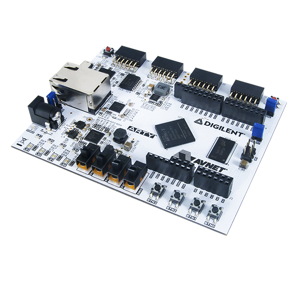
Board: Arty A7-35T by Digilent
-
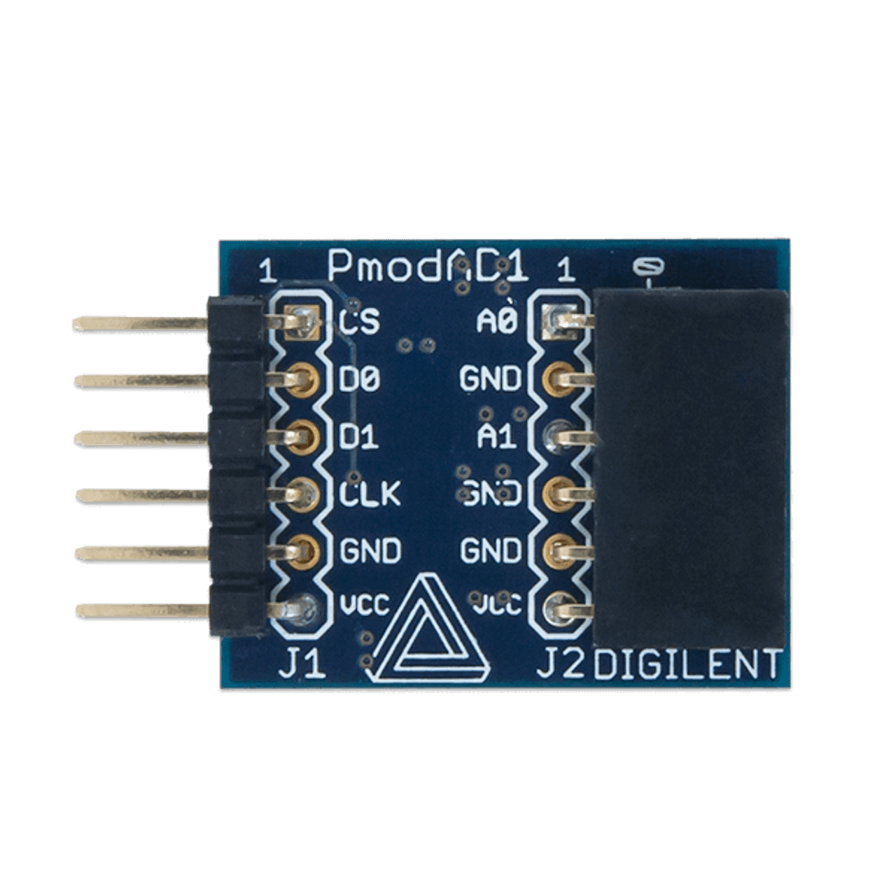
Pmod AD1 :
The PmodAD1 contains a pair of AD7476A ADCs by Analog Devices
-
Reference manual PmodAD1 link
-
Datasheet AD7476A PDF link
-
The software used is Vivado 2021.1 by Xilinx
-
The HDL language used is SystemVerilog and a little of VHDL (see below).
Let's see the configuration for the pins on the board.
Below is reported the schematic of the Pmod interface.
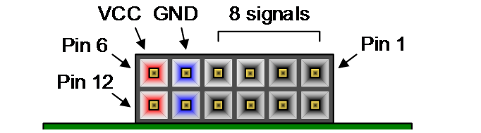
I have used the JC interface since it is configured to run at High-speeds.
| Pin figure | Pin XDC (vector) | Pin FPGA | Pmod connection | Direction |
|---|---|---|---|---|
| 1 | 0 | U12 | Not used | -- |
| 2 | 1 | V12 | Not used | -- |
| 3 | 2 | V10 | Not used | -- |
| 4 | 3 | V11 | Not used | -- |
| 7 | 4 | U14 | CS negation | Output |
| 8 | 5 | V14 | D0 (MISO) | Input |
| 9 | 6 | T13 | D1 (MISO) | Input |
| 10 | 7 | U13 | CLK | Output |
Note :
- Input : from the external Pmod towards the FPGA
- Output : from the FPGA towards the external device
- 02/04/2022:
- XADC channels are set to the unipolar mode.
- DC blocking filter added for testing
- Additional Most Significant Bit (MSB) added to the 12 bit data bus to prevent overflow in the DSP. In this way if we perform a subtraction and we interpret the signal in the bipolar notation (2's complement for negative numbers) and the result is negative, the information about the sign is preserved and the value can safely oscillate about 0. This is important for the DC filtering since we want an AC signal without any offset.
The Sampler realised with the Arty A7 35T developement board takes four analog signals from the outside and it returns on screen, via the UART cable, the digitalised values. The update frequency of the ADC is about 10 Hz, but in principle it can be modified from the Top module changing the parameters. Once the FPGA is programmed and the UART cable is connected to the computer, thanks to a serial reader like PuTTY it is possible to display the following data

From left to right:
- Time measured in milliseconds (8 digits)
- Channel A0 XADC (5 digits)
- Channel A1 XADC (5 digits)
- Channel A0 PmodAD1 (5 digits)
- Channel A1 PmodAD1 (5 digits)
Analog signals are sampled by the XADC in bipolar mode (input signal can range from -0.5 V to 0.5 V). The signal is digitalised using the 2's complement notation for the negative potentials. Then, by switching the most significant bit (MSB), the number is displayed on the terminal screen using the unipolar representation (See the XADC repository on my GitHub page).
The core containing the SPI interface to collect data from the PmodAD1 can be found at the following website Digi-Key link. The core is written in VHDL. Vivado, the tool provided by Xilinx, allow the language mixing within a project. Hence, using the traditional Verilog instantiation template, it is possible to use the VHDL core.
To build up the design I have used some IPs by Xilinx. These modules can be configurated from the IP catalogue in Vivado. To create your personal module follow these steps:
- Click on IP catalogue in the Project flow navigator
- Search for the desired IP. In our case the IPs used are the XADC Wiziard and the FIFO generator
- Click on the IP desired
- Customize the IP according to the fatures required
- Click on Generate IP instance
- Then you have to generate and synthesise the required files (Click on Generate in the pop-up window).
- In the file manager, where you can see the Source Hierarchy click on the IP sources panel.
- In the path: IP_COMPONENT_NAME >> Instantiation template >> ... youìll find the two Instantiation templates, one written in Verilog HDL and the other in VHDL. Now you can instantiate your customised module into your design.
Xilinx xadc interface:
- XADC in sequence mode
- DRP interface is connected to atomtically readout the pre-designated channels
- The readout is stored into corresponding register
Arty board configuration
- vp/vn channel
- 13 aux channels:
- 6 single-ended channels
- 3 differential channels
- 4 on-board voltage/current channels
- The design enables all 16 aux channels and 16 aux reading in a register file. vp/temp/vcc in three registers.
Channel mapping (arty signal: aux)
- Single-ended channels (max=3V via voltage divider)
- a0: 4
- a1: 5
- a2: 6
- a3: 7
- a4: 15
- a5: 0
- differential channels (max=1V)
- a6/a7: 12 (diff)
- a8/a9: 13 (diff)
- a10/a11: 14 (diff)
- On-board v-i channel (not used)
| # | PIN | DADDR | Channel ADC |
|---|---|---|---|
| 1. | v_P / v_N | 03h | DEDICATED DIFFERENTIAL |
| 2. | A0 | 14h | Channel 4 |
| 3. | A1 | 15h | Channel 5 |
| 4. | A2 | 16h | Channel 6 |
| 5. | A3 | 17h | Channel 7 |
| 6. | A4 | 1Fh | Channel 15 |
| 7. | A5 | 10h | Channel 0 |
| 8. | A6+ / A7- | 1Ch | Channel 12 |
| 9. | A8+ / A9- | 1Dh | Channel 13 |
| 10. | A10+ / A11- | 1Eh | Channel 14 |
Here some useful online resources which I have used to develope this simple ADC sampler:
- Digilent reference webpage (Arty A7) : https://digilent.com/reference/programmable-logic/arty-a7/start
- Arty A7 reference manual link
- OpenCores (a useful web platform where it is possible to find HDL open source cores) :link
- Companion website for the book FPGA prototyping by SystemVerilog examples by Dr. Chu : link
- Xilinx Vivado website: link
- Digilent GitHub repositories : link
- Pmod AD1 resource center link
- ADC AD7476A Pmod Controller (VHDL) from Digi-key website link
To build up a Vivado project, the following operations are required:
- Open Vivado
- Click on New project
- Give a name to the project and click on Create project subdirectory and click on Next
- Click on RTL project. Then, click Next
- Now choose all the sources files .v (if the files are written in verilog), .sv (if they are written in SystemVerilog), .vhd (if files are written in VHDL), click on Scan and add RTL include files into the project and Copy sources into project. Then, click on Next
- Import the Costraint file .xdc in the same manner as before.
- Now you need to select the Target device. To do this, select the Boards menu and search for ARTY A7-35T. To do this operation you need to install on your computer the Digilent boards files. This procedure is described at the following link https://digilent.com/reference/programmable-logic/guides/installing-vivado-and-vitis if you use the latest versions of Vivado and Vitis unified platform or the following link https://digilent.com/reference/programmable-logic/guides/installing-vivado-and-sdk if you use Vivado and Vivado SDK.
- Now it is possible to modify the project, run the synthesis, the implementation and the bitstream generation