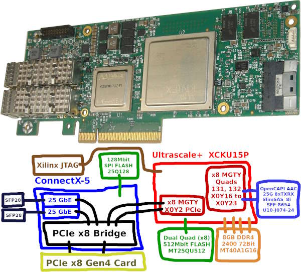
The Nvidia Mellanox Innova-2 Flex Open Programmable SmartNIC accelerator card, model MNV303212A-ADLT, can be used as an FPGA development platform. It is based on the Mellanox ConnectX-5 MT27808 and Xilinx Ultrascale+ XCKU15P. It is a high capacity FPGA with 8GB DDR4, connected through a PCIe x8 switch in the ConnectX-5.
These notes include step-by-step instructions for setting up an Innova-2 system and preparing the Innova-2 for FPGA development.
If you experience any problems, search the Nvidia SoC and SmartNIC Forum and this project's Issues.
- Required Materials
- Cooling Solution
- System Setup
- Test the Innova-2
- Programming the FPGA
- Loading Updated Designs Using JTAG
- Upgrading the ConnectX5 Firmware
- Troubleshooting
- W25Q128JVS FLASH Failure
- Factory Image Running with Flex Image Scheduled
- Innova2 Flex App Will Not Program
- Innova2 Flex App No BOPE or ConnectX Devices
- DDR4 Communication Error
- JTAG Programming Failure
- innova2_flex_app stuck on Erasing Flash
- xsdb Cannot Download Program
- Board Works But Not JTAG
- Nothing Seems to Work
- Disable or Enable Resizable BAR Support
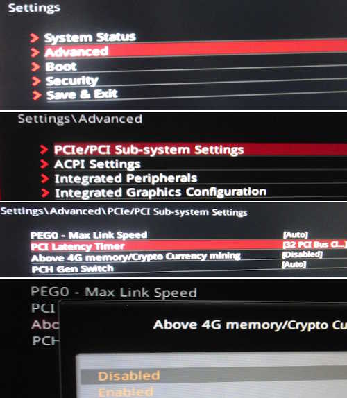
- Disable or Enable Above-4G Memory Decoding
- JTAG Using UrJTAG
- FPGA Design Notes
- Useful Commands
- Useful Links
- Projects Tested to Work with the Innova2
- Innova-2 Flex SmartNIC
- Computer with 16GB+ of RAM (preferably 32GB+ and a CPU with Integrated Graphics)
- Cooling Solution (blower fan, large heatsink, thermal pads)
- Xilinx-Compatible 1.8V JTAG Adapter
- Second Computer or External Powered PCIe Adapter to program Flex and Factory Images via JTAG
- SFP28/SFP+/SFP Modules and Cable or Direct-Attach Cable to test network ports
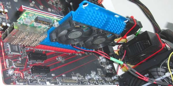
The card is designed for use in servers and requires active cooling with up to 800 LFM of air flow. My Innova-2 came without a cooling solution so I attached a hard drive heat sink to it and placed a 12V 1.3A blower fan from a server in line with the card. I have the board in an open air setup with no enclosure. I run the blower fan from a 5V power rail and get acceptable noise and performance when using only the FPGA. I need to run the fan at 12V when testing the network interfaces. The board otherwise overheats and the interfaces shut down.
The two main ICs are different heights so I needed 2mm and 0.5mm thermal pads.
The Innova-2 requires a specific system setup. Ubuntu 20.04.4 with Linux Kernel 5.8.0-43 and MLNX_OFED 5.2-2.2.4.0 drivers is a fully tested combination that works for me. I am running the card in the second PCIe slot of a system with 16GB of memory and a CPU with Integrated Graphics. Using the second PCIe slot prevents issues with the motherboard assuming the Innova-2 is a video card. A CPU with Integrated Graphics prevents conflicts between the Innova-2 and a Video Card and is useful when debugging PCIe designs.
I recommend starting with a fresh Ubuntu install on a blank SSD. An approximately 250GB SSD is enough for a working system that includes full Vivado 2021.2. 50GB drive space is enough for a working system with Vivado Lab Edition for basic functionality testing of the Innova-2.
Begin by updating and upgrading your Ubuntu 20.04.4 Desktop amd64 install but make sure to stay on 20.04, no dist-upgrade. Run the following in a terminal. Run sudo ls before copy-and-pasting a large block of commands to prime sudo and avoid copying commands into the password field.
sudo apt-get update ; sudo apt-get upgradeInstall Linux Kernel 5.8.0-43-generic which is the latest kernel I have found to work.
sudo apt-get install   linux-buildinfo-5.8.0-43-generic \
       linux-cloud-tools-5.8.0-43-generic linux-headers-5.8.0-43-generic \
       linux-image-5.8.0-43-generic linux-modules-5.8.0-43-generic \
       linux-modules-extra-5.8.0-43-generic linux-tools-5.8.0-43-generic
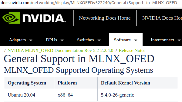
Nvidia/Mellanox only officially support kernel 5.4.0-26-generic. Xilinx appears to have only thoroughly tested Vivado 2021.2 against 5.8.0.
sudo gedit /etc/default/grub and edit GRUB's configuration to the following:
### change timeout to 3s and add a menu
#GRUB_DEFAULT=0
GRUB_DEFAULT="Advanced options for Ubuntu>Ubuntu, with Linux 5.8.0-43-generic"
GRUB_TIMEOUT_STYLE=menu
GRUB_HIDDEN_TIMEOUT_QUIET=false
GRUB_TIMEOUT=3
GRUB_DISTRIBUTOR=`lsb_release -i -s 2> /dev/null || echo Debian`
GRUB_CMDLINE_LINUX_DEFAULT=""
GRUB_CMDLINE_LINUX="net.ifnames=0 biosdevname=0"
The net.ifnames=0 biosdevname=0 options allow traditional network interface names, such as eth0. This is required for older versions of Vivado, such as 2017.2.
Update grub.
sudo update-grubList all installed Linux Kernels:
dpkg -l | grep linux-image | grep "^ii"Kernels 5.13.0-30-generic and 5.13.0-52-generic show up for me in the above command so I remove them both as they are not 5.8.0-43. Mellanox OFED driver installation attempts to compile kernel modules for every kernel on the system and it will fail to install properly if it cannot.
sudo apt remove \
       linux-buildinfo-5.13.0-52-generic \
       linux-cloud-tools-5.13.0-52-generic linux-headers-5.13.0-52-generic \
       linux-image-5.13.0-52-generic linux-modules-5.13.0-52-generic \
       linux-modules-extra-5.13.0-52-generic linux-tools-5.13.0-52-generic \
       \
       linux-buildinfo-5.13.0-30-generic \
       linux-cloud-tools-5.13.0-30-generic linux-headers-5.13.0-30-generic \
       linux-image-5.13.0-30-generic linux-modules-5.13.0-30-generic \
       linux-modules-extra-5.13.0-30-generic linux-tools-5.13.0-30-generic

sudo apt autoremove
sudo reboot
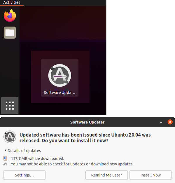
After reboot run Ubuntu Software Updater.
Confirm you are on kernel 5.8.0-43-generic
uname -s -r -m
Install all necessary prerequisite libraries and software. MLNX_OFED drivers will install custom versions of some of the libraries that get pulled into this install. By installing everything first you can avoid library incompatibility issues and MLNX_OFED reinstallations. libibverbs is one package that gets updated and pulled in by almost every piece of networking software but MLNX_OFED requires a custom version.
sudo apt install    alien apt autoconf automake binfmt-support \
    binutils-riscv64-unknown-elf binwalk bison bpfcc-tools build-essential \
    bzip2 chrpath clang clinfo cmake coreutils curl cycfx2prog dapl2-utils \
    debhelper debootstrap devmem2 dh-autoreconf dh-python dkms dos2unix \
    doxygen dpatch dpdk elfutils fio flashrom flex fxload gcc gcc-multilib \
    gcc-riscv64-unknown-elf gdb gfortran gfortran-multilib ghex git \
    graphviz gtkterm gtkwave hwdata ibacm ibutils ibverbs-providers \
    ibverbs-utils intel-opencl-icd iperf3 ixo-usb-jtag kcachegrind libaio1 \
    libaio-dev libasm1 libbpfcc libbpfcc-dev libbsd0 libc6 libc6-dev \
    libcap-dev libc-dev libcharon-extauth-plugins libclang-dev libcunit1 \
    libcunit1-dev libdapl2 libdrm-dev libdw1 libdwarf++0 libedit-dev \
    libegl1-mesa-dev libelf++0 libelf1 libelf-dev libelfin-dev libfdt1 \
    libfdt-dev libfontconfig1-dev libfreetype6-dev libftdi1 libftdi1-dev \
    libftdi1-doc libftdi-dev libgfortran4 libglib2.0-0 libglib2.0-bin \
    libglib2.0-data libglib2.0-dev libhugetlbfs-bin libibdm1 libibmad5 \
    libibmad-dev libibnetdisc5 libibnetdisc-dev libibumad-dev libibverbs1 \
    libibverbs-dev libipsec-mb0 libipsec-mb-dev libisal2 libisal-dev \
    libjansson4 libjpeg-dev liblzma-dev libmfx1 libmfx-dev libmfx-tools \
    libmnl0 libmnl-dev libmount-dev libncurses5 libncurses-dev libnl-3-200 \
    libnl-3-dev libnl-route-3-200 libnl-route-3-dev libnuma-dev \
    libopencl-clang10 libpcap-dev libprocps-dev librdmacm1 librdmacm-dev \
    libreadline-dev librte-pmd-qat20.0 libselinux1 libselinux1-dev \
    libsgutils2-dev libssl-dev libstdc++-9-dev-riscv64-cross \
    libstdc++-9-pic-riscv64-cross libstrongswan \
    libstrongswan-standard-plugins libsystemd0 libsystemd-dev libtiff5 \
    libtiff-dev libtinfo5 libtinfo-dev libtool libudev-dev libunbound8 \
    libunbound-dev libunwind8 libunwind-dev libusb-1.0-0-dev libusb-dev \
    libvma libvma-dev libxext-dev libxfixes-dev libxft-dev llvm-dev \
    logrotate lsb-base make mdevctl meld mesa-opencl-icd meson \
    module-assistant ninja-build nmap ntpdate nvme-cli ocl-icd-dev \
    ocl-icd-libopencl1 ocl-icd-opencl-dev opencl-headers openjdk-17-jdk \
    openjdk-17-jre openocd opensbi opensm openssl openvswitch-switch pandoc \
    pciutils perftest perl pkg-config procps python python3-all \
    python3-attr python3-automat python3-binwalk python3-bpfcc \
    python3-constantly python3-docutils python3-ftdi1 python3-hamcrest \
    python3-hyperlink python3-incremental python3-openpyxl python3-openssl \
    python3-pip python3-pkgconfig python3-pyasn1 python3-pyasn1-modules \
    python3-pyelftools python3-pyverbs python3-scapy \
    python3-service-identity python3-setuptools python3-six python3-sphinx \
    python3-twisted python3-twisted-bin python3-zope.interface python-six \
    python-zope.interface qemu-system-misc qemu-system-x86 qemu-utils quilt \
    rdmacm-utils sg3-utils sockperf squashfs-tools squashfs-tools-ng \
    squashfuse strongswan strongswan-charon strongswan-libcharon \
    strongswan-starter swig tcl-dev tcptraceroute tk-dev u-boot-qemu udev \
    v4l2loopback-dkms v4l2loopback-utils valgrind valgrind-mpi vbindiff \
    vtun xc3sprog xxd zlib1g zlib1g-dev

sudo apt install    dpkg-dev:i386 libgtk2.0-0:i386 libstdc++6:i386
Need to remove some extra packages that conflict with Mellanox OFED.
sudo apt-get remove  openmpi-bin libcoarrays-openmpi-dev \
       libiscsi-bin dpdk-dev libmumps-5.2.1 librte-pmd-mlx4-20.0 \
       libsdpa-dev librte-pmd-mlx5-20.0 libcaf-openmpi-3 \
       libscotch-dev libopensm-dev libosmvendor4 libopensm8 \
       mpi-default-dev libmumps-seq-dev libopenmpi3 \
       libscalapack-openmpi2.1 libopenmpi-dev openmpi-common \
       libiscsi-dev libdpdk-dev libbibutils-dev \
       libscalapack-openmpi-dev libvma8 libfabric1 libmumps-dev \
       libbibutils6 libosmcomp4 libscalapack-mpi-dev libiscsi7 \
       mpi-default-bin
Run update, autoremove, and upgrade one last time. Reboot.
sudo apt-get update  ;  sudo apt autoremove  ;  sudo apt-get upgrade
sudo rebootConfirm you are on kernel 5.8.0-43-generic
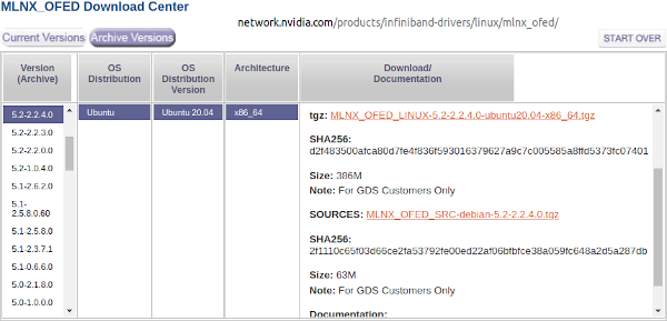
uname -s -r -mMLNX_OFED-5.2-2.2.4.0 is the latest version that includes the mlx5_fpga_tools kernel module required to program the FPGA's Configuration Memory using innova2_flex_app.
Run the following commands individually, which download and install MLNX_OFED-5.2-2.2.4.0.
cd ~
wget https://content.mellanox.com/ofed/MLNX_OFED-5.2-2.2.4.0/MLNX_OFED_LINUX-5.2-2.2.4.0-ubuntu20.04-x86_64.tgz
sha256sum  MLNX_OFED_LINUX-5.2-2.2.4.0-ubuntu20.04-x86_64.tgz
echo d2f483500afca80d7fe4f836f593016379627a9c7c005585a8ffd5373fc07401 should be the SHA256 checksum
tar -xvf  MLNX_OFED_LINUX-5.2-2.2.4.0-ubuntu20.04-x86_64.tgz
cd MLNX_OFED_LINUX-5.2-2.2.4.0-ubuntu20.04-x86_64/
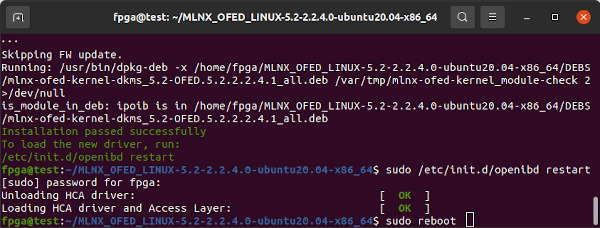
sudo ./mlnxofedinstall -vvv --without-fw-update --skip-unsupported-devices-check
sudo /etc/init.d/openibd restart

sudo reboot
apt-mark hold should prevent apt from updating any of the packages installed by MLNX_OFED.
sudo  apt-mark  hold     5.8.0-43-generic linux-image-generic \
    linux-headers-generic ofed-scripts mlnx-ofed-kernel-utils \
    mlnx-ofed-kernel-dkms iser-dkms isert-dkms srp-dkms rdma-core \
    libibverbs1 ibverbs-utils ibverbs-providers libibverbs-dev \
    libibverbs1-dbg libibumad3 libibumad-dev ibacm librdmacm1 \
    rdmacm-utils librdmacm-dev mstflint ibdump libibmad5 \
    libibmad-dev libopensm opensm opensm-doc libopensm-devel \
    libibnetdisc5 infiniband-diags mft kernel-mft-dkms perftest \
    ibutils2 ar-mgr dump-pr ibsim ibsim-doc ucx sharp hcoll \
    knem-dkms knem openmpi mpitests libdapl2 dapl2-utils \
libdapl-dev dpcp srptools mlnx-ethtool mlnx-iproute2After reboot confirm Kernel Modules are Installed.
sudo dkms statusConfirm the installed version of Mellanox OFED.
ofed_info -nDownload and extract the March 18, 2022, commit 7859957 version of Xilinx's DMA IP Drivers.
cd ~
wget https://codeload.github.com/Xilinx/dma_ip_drivers/zip/785995783c78b2cbec6458141c4395e204c5bd9b -O dma_ip_drivers-7859957.zip
unzip dma_ip_drivers-7859957.zip
mv dma_ip_drivers-785995783c78b2cbec6458141c4395e204c5bd9b dma_ip_driversDPDK requires hugepages.
sudo su
echo 1024 > /sys/kernel/mm/hugepages/hugepages-2048kB/nr_hugepages
exit
DPDK v20.11.5 LTS is the latest version that works with Xilinx's dma_ip_drivers 7859957. DPDK needs to be compiled and installed from source as dma_ip_drivers requires DPDK's librte to be built with QDMA support from dma_ip_drivers so that dma_ip_drivers can compile with a librte that supports QDMA so that XDMA drivers can build.
cd ~
git clone --recursive -b v20.11.5 --single-branch https://dpdk.org/git/dpdk-stable
cd dpdk-stable
git checkout v20.11.5
git describe --tags
git clone git:https://dpdk.org/dpdk-kmods
echo Copy QDMA-related files from dma_ip_drivers
cp -r ~/dma_ip_drivers/QDMA/DPDK/drivers/net/qdma ./drivers/net/
cp -r ~/dma_ip_drivers/QDMA/DPDK/examples/qdma_testapp ./examples/
echo Configure DPDK for more ethernet ports
echo "dpdk_conf.set('RTE_MAX_ETHPORTS', 256)"     >>config/meson.build
echo "dpdk_conf.set('RTE_MAX_VFIO_GROUPS', 256)"  >>config/meson.build
gedit drivers/net/meson.build and add QDMA support to your DPDK build in meson.build. After 'mlx5', add 'qdma',
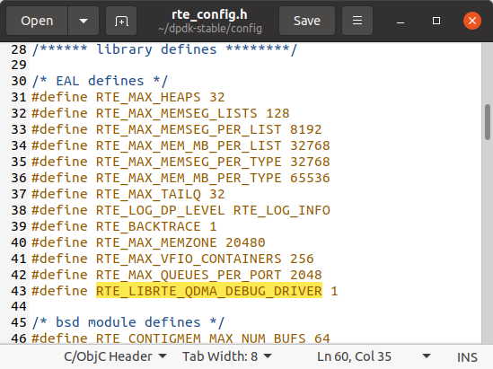
gedit config/rte_config.h and search for EAL defines in rte_config.h to change/add the following values:
#define RTE_MAX_MEMZONE 20480
#define RTE_MAX_VFIO_CONTAINERS 256
#define RTE_MAX_QUEUES_PER_PORT 2048
#define RTE_LIBRTE_QDMA_DEBUG_DRIVER 1
gedit usertools/dpdk-devbind.py and add Xilinx QDMA Vendor and Device IDs amongst similar vendor definitions in dpdk-devbind.py:
xilinx_qdma_pf = {'Class': '05', 'Vendor': '10ee',
  'Device': '9011,9111,9211, 9311,9014,9114,9214,9314,9018,9118,\
  9218,9318,901f,911f,921f,931f,9021,9121,9221,9321,9024,9124,9224,\
  9324,9028,9128,9228,9328,902f,912f,922f,932f,9031,9131,9231,9331,\
  9034,9134,9234,9334,9038,9138,9238,9338,903f,913f,923f,933f,9041,\
  9141,9241,9341,9044,9144,9244,9344,9048,9148,9248,9348',
  'SVendor': None, 'SDevice': None}

xilinx_qdma_vf = {'Class': '05', 'Vendor': '10ee',
  'Device': 'a011,a111,a211,a311,a014,a114,a214,a314,a018,a118,\
  a218,a318,a01f,a11f,a21f,a31f,a021,a121,a221,a321,a024,a124,a224,\
  a324,a028,a128,a228,a328,a02f,a12f,a22f,a32f,a031,a131,a231,a331,\
  a034,a134,a234,a334,a038,a138,a238,a338,a03f,a13f,a23f,a33f,a041,\
  a141,a241,a341,a044,a144,a244,a344,a048,a148,a248,a348',
  'SVendor': None, 'SDevice': None}
Change (also in dpdk-devbind.py)
network_devices = [network_class, cavium_pkx, avp_vnic, ifpga_class]to
network_devices = [network_class, cavium_pkx, avp_vnic, ifpga_class, xilinx_qdma_pf, xilinx_qdma_vf]Build DPDK:
cd ~/dpdk-stable
meson build
cd build
ninja
sudo ninja install
sudo ldconfig
cd ../examples/helloworld/
make
Confirm DPDK built correctly:
cd build
sudo ./helloworld-shared
Above should produce output similar to:
 EAL: Detected 4 lcore(s)
 EAL: Detected 1 NUMA nodes
 EAL: Multi-process socket /var/run/dpdk/rte/mp_socket
 EAL: Selected IOVA mode 'PA'
 EAL: No available hugepages reported in hugepages-1048576kB
 EAL: Probing VFIO support...
 EAL: VFIO support initialized
 hello from core 1
 hello from core 2
 hello from core 3
 hello from core 0
Build igb_uio.
cd ~/dpdk-stable/dpdk-kmods/linux/igb_uio
make
Confirm librte_net_qdma.a was built and exists.
ls -la ~/dpdk-stable/build/drivers/ | grep librte_net_qdma.a
Edit dma_ip_drivers's QDMA to enable Xilinx Virtual Cable (XVC). Uncomment export enable_xvc in dma_ip_drivers/QDMA/linux-kernel/driver/Makefile:
Continue to build QDMA test application:
cd ~/dpdk-stable/examples/qdma_testapp/
make  RTE_SDK=`pwd`/../..  RTE_TARGET=build
sudo build/qdma_testapp-shared
Above should produce output similar to:
 QDMA testapp rte eal init...
 EAL: Detected 4 lcore(s)
 EAL: Detected 1 NUMA nodes
 EAL: Multi-process socket /var/run/dpdk/rte/mp_socket
 EAL: Selected IOVA mode 'VA'
 EAL: No available hugepages reported in hugepages-2048kB
 EAL: Probing VFIO support...
 EAL: VFIO support initialized
 EAL: No legacy callbacks, legacy socket not created
 Ethernet Device Count: 0
 Logical Core Count: 4
 EAL: Error - exiting with code: 1
   Cause: No Ethernet devices found. Try updating the FPGA image.
Need a personal signing key for compiled kernel modules. Run sudo ls to prime sudo then copy and paste the following into a command terminal and it should generate a key configuration.
cd /lib/modules/$(uname -r)/build/certs

sudo tee x509.genkey > /dev/null << 'EOF'
[ req ]
default_bits = 4096
distinguished_name = req_distinguished_name
prompt = no
string_mask = utf8only
x509_extensions = myexts
[ req_distinguished_name ]
CN = Modules
[ myexts ]
basicConstraints=critical,CA:FALSE
keyUsage=digitalSignature
subjectKeyIdentifier=hash
authorityKeyIdentifier=keyid
EOF
Generate custom key and reboot.
sudo openssl req -new -nodes -utf8 -sha512 -days 36500 -batch -x509 -config x509.genkey -outform DER -out signing_key.x509 -keyout signing_key.pem
sudo rebootcd ~/dma_ip_drivers/QDMA/linux-kernel/
make
sudo make install
cd ~/dma_ip_drivers/XDMA/linux-kernel/xdma/
make
sudo make install
sudo depmod -a
sudo ldconfig
cd ~/dma_ip_drivers/XDMA/linux-kernel/tools
make
sudo rebootThe innova2_flex_app, part of the Innova-2 Flex Firmware Release, allows software update of the XCKU15P FPGA User Image as well as basic diagnostics of the Innova-2.
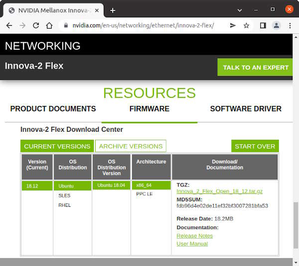
The following commands download and install Innova_2_Flex_Open_18_12.
cd ~
wget https://www.mellanox.com/downloads/fpga/flex/Innova_2_Flex_Open_18_12.tar.gz
md5sum Innova_2_Flex_Open_18_12.tar.gz
echo fdb96d4e02de11ef32bf3007281bfa53 should be the MD5 Checksum
tar -xvf Innova_2_Flex_Open_18_12.tar.gz
cd ~/Innova_2_Flex_Open_18_12/driver/
make
sudo depmod -a
cd ~/Innova_2_Flex_Open_18_12/app/
make

sudo rebootVivado is not strictly required on the system with the Innova-2. A seperate computer with Vivado can be used for development and JTAG. However, if you intend to develop with any of Xilinx's Accelerator Projects, they require the Xilinx Runtime XRT which requires Vitis, which requires Vivado.
Create a symbolic link for gmake which Vivado requires but Ubuntu already includes as make.
sudo ln -s /usr/bin/make /usr/bin/gmakeInstall libpng12 which is required by Vivado.
cd ~
mkdir tmppng12
wget https://mirrors.kernel.org/ubuntu/pool/main/libp/libpng/libpng12-0_1.2.54-1ubuntu1_amd64.deb
dpkg-deb -R  libpng12-0_1.2.54-1ubuntu1_amd64.deb  tmppng12
sudo mv  tmppng12/lib/x86_64-linux-gnu/libpng12.so.0.54.0  /lib/x86_64-linux-gnu/
sudo chown root:root /lib/x86_64-linux-gnu/libpng12.so.0.54.0
sudo ln -r -s /lib/x86_64-linux-gnu/libpng12.so.0.54.0  /lib/x86_64-linux-gnu/libpng12.so.0
rm -Rf tmppng12/
Install Xilinx Vivado ML 2021.2 or Xilinx Vivado ML 2023.2. Vivado 2023.2 is the latest version which has successfully synthesized and implemented a basic Innova-2 DDR4 design for me. 2018.3 and 2020.2 also worked. 2021.1 and 2017.2 fail. If download size is an issue, download only Vivado Lab Edition for now which is enough to test the Innova-2's FPGA. There are only modest savings in bandwidth and space requirements when using the Web Installer so you may as well download the complete 72GB Xilinx Unified Installer 2021.2 SFD offline package.
If you have decided to install full Vivado, select Vitis (which will include Vivado) and at least Kintex Ultrascale+ and Zynq Ultrascale+ MPSoC under device support. Zynq Ultrascale+ MPSoC seems to pull in some files needed by Vitis.
Refer to the Vivado Release Notes for more info. You will also need to obtain a Vivado License, such as an Evaluation License.
Run the following commands individually.
echo c6f91186f332528a7b74a6a12a759fb6 should be the MD5 Checksum Value
md5sum Xilinx_Unified_2021.2_1021_0703.tar.gz
tar -xvf Xilinx_Unified_2021.2_1021_0703.tar.gz
cd Xilinx_Xilinx_Unified_2021.2_1021_0703/
sudo ./xsetup
cd /tools/Xilinx/Vivado/2021.2/data/xicom/cable_drivers/lin64/install_script/install_drivers/
sudo ./install_drivers
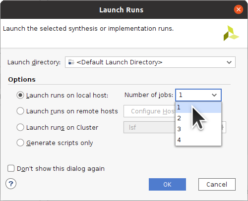
Vivado requires 4GB of system RAM per Job (Thread) plus a base of 10GB. An Ubuntu system with 16GB of RAM running just Vivado can reliably use only 1 core during synthesis and implementation. Otherwise, it will overwhelm the Kernel Swap Daemon.
Power off your system. Then plug the Innova-2 into your system and power on.
Check if it shows up in lspci.
sudo lspci | grep -i mellanoxIf the Innova-2 does not show up, try a different PCIe slot. It should work in any x16 or x8 slot or even in an x1 with an appropriate adapter. If it does not, proceed to Programming the ConnectX FLASH IC.
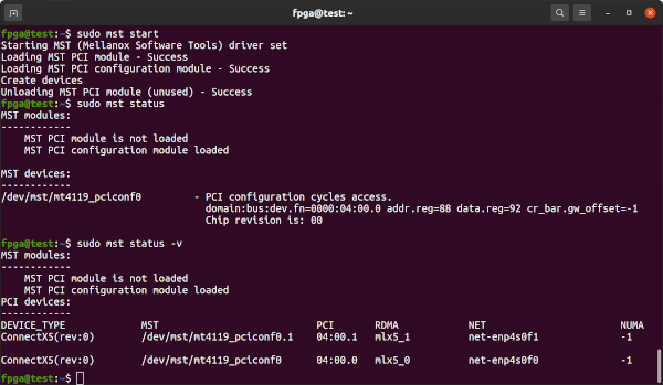
Start Mellanox Software Tools (mst) to find the Innova-2's device address. Note the /dev/mst/mt4119_pciconf0 or similar which will be needed later.
sudo mst start
sudo mst status
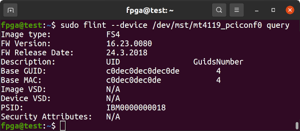
sudo mst status -vRun Mellanox's Flash Interface Tool flint for information on the Innova-2's ConnectX-5 firmware.
sudo mst start
sudo flint --device /dev/mst/mt4119_pciconf0 query
If the result is PSID: MT_0000000158 then you can attempt to program the firmware using flint. Otherwise, the next step may require physical access to the board. My device presented as PSID: IBM0000000018 and needed to be programmed. sudo mst start must be run to enable flint.
Make sure to write down the GUID and MAC values.
If the FW Version is 16.24.4020 or newer then proceed to Testing The Network Ports as firmware is already up-to-date.
Attempt to program the firmware using flint. The 25GbE SFP28 MT27808A0 MNV303212A-ADLT with 8GB of DDR4 is nicknamed Morse while the 100GbE QSFP MT28808A0 MNV303611A-EDLT is nicknamed MorseQ and its firmware is in MorseQ_FW. cd into the appropriate directory.
cd ~/Innova_2_Flex_Open_18_12/FW/Morse_FW/
sudo flint --device /dev/mst/mt4119_pciconf0 --image fw-ConnectX5-rel-16_24_4020-MNV303212A-ADL_Ax.bin --allow_rom_change burn
If the above works, proceed to Testing The Network Ports. If it fails as above due to a -E- PSID mismatch or other error, continue with programming the ConnectX5 Firmware FLASH IC.
If your ConnectX-5 Firmware shows up as PSID: IBM0000000018 or is too old to update with flint you will need to update it so that it works with innova2_flex_app. There are three methods: Corrupting the firmware and using mstflint, using a programmer, or by forcing the board into Recovery Mode. Each option has associated risks.
mstflint does not allow you to overwrite ConnectX-5 firmware if there is a PSID mismatch but it will allow you to write arbitrary data to the flash IC. By corrupting the firmware and causing a CRC error you can enable mstflint to program new firmware.
First, save copies of the current firmware using both Read Block (rb) and Read Image (ri) methods. This will NOT be an exact copy of the firmware IC as only the executable sections are saved. Consider reading the Flash using an SPI programmer if you want to be certain you have a complete copy of the FLASH IC.
The device ID is the PCI address of the first Mellanox Ethernet Controller found using lspci -vnn -d 15b3:. Be careful if your system has other Mellanox devices installed.
sudo mstflint --device 04:00.0  rb  FW_SAVE1.bin
sudo mstflint --device 04:00.0  rb  FW_SAVE2.bin
sudo mstflint --device 04:00.0  ri  FW_SAVE3.bin
sudo mstflint --device 04:00.0  ri  FW_SAVE4.bin
Attempt to program the firmware using mstflint. The 25GbE SFP28 MT27808A0 MNV303212A-ADLT with 8GB of DDR4 is nicknamed Morse while the 100GbE QSFP MT28808A0 MNV303611A-EDLT is nicknamed MorseQ and its firmware is in MorseQ_FW. cd into the appropriate directory.
cd ~/Innova_2_Flex_Open_18_12/FW/Morse_FW/
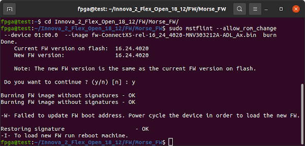
sudo mstflint --nofs --use_image_ps --ignore_dev_data  --device 04:00.0  --image fw-ConnectX5-rel-16_24_4020-MNV303212A-ADL_Ax.bin  burn
If programming succeeds, proceed to update the GUID and MAC IDs. Otherwise, write some data to corrupt the ConnectX-5 firmware. The exact memory locations and data are not critical but I found the following to work when I tried to modify the PSID.
sudo mstflint --device 04:00.0 ww 0x00357734 0x30303135
sudo mstflint --device 04:00.0 ww 0x00357738 0x38000000
Confirm there is now a CRC error with the ConnectX-5 firmware.
sudo mstflint --device 04:00.0 query
Program the ConnectX-5 firmware. The Current FW should show up as N/A due to the CRC error.
sudo mstflint --nofs --use_image_ps --ignore_dev_data --device 04:00.0 --image fw-ConnectX5-rel-16_24_4020-MNV303212A-ADL_Ax.bin burn
If the above worked, proceed to update the GUID and MAC IDs. If it fails, try the following method of Forcing Recovery Mode.
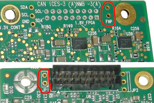
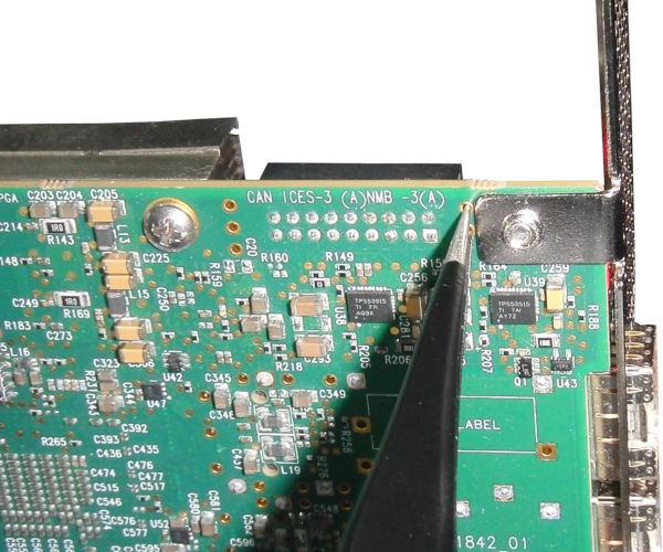
Thanks michalkouril for pointing out that the unpopulated FNP Header stands for Firmware-Not-Present and can be shorted to boot the board into Firmware Recovery Mode if the above fails.
Power down the system. Then short the Header using wire or tweezers and turn the system on.
If all goes well the Innova-2 should show up as Memory controller [0580]: Mellanox Technologies MT28800 Family [ConnectX-5 Flash Recovery] [15b3:020d] under lspci -vnn. It should show up as /dev/mst/mt525_pciconf0 under mst status. The 25GbE SFP28 MNV303212A-ADLT with 8GB DDR4 is nicknamed Morse while the 40GbE/100GbE QSFP MNV303611A-EDLT without DDR memory is nicknamed MorseQ. cd into the appropriate directory.
sudo lspci -vnn
cd ~/Innova_2_Flex_Open_18_12/FW/Morse_FW/
ls
sudo mst start
sudo mst status
sudo flint --device /dev/mst/mt525_pciconf0 query
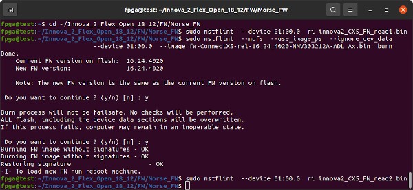
Save a copy of the current FLASH IC firmware then program the ConnectX-5 firmare using mstflint. The device name is the PCI address from lspci -vnn
sudo mstflint --device 01:00.0  ri  innova2_CX5_FW_read1.bin
sudo mstflint --nofs --use_image_ps --ignore_dev_data  --device 01:00.0  --image fw-ConnectX5-rel-16_24_4020-MNV303212A-ADL_Ax.bin  burn
sudo mstflint --device 01:00.0  ri  innova2_CX5_FW_read2_after_write.bin
Remove the FNP Header short and reboot your system. Proceed to Update GUID and MAC IDs.
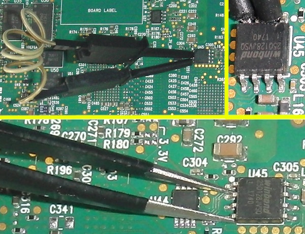
Thanks yangl1996 for pointing out the ConnectX-5 can be forced into Flash Recovery Mode and its FLASH read and written with mstflint. Shorting the W25Q128JVS FLASH IC's pins 2 (DO=Data Output) and 4 (GND) during boot prevents the firmware from loading and should put the ConnectX-5 into Recovery Mode. Hold the short until the Operating System has fully loaded so that the board is recognized as being in Recovery Mode. Use precision metal tweezers or fine pitch SMD Grabber Test Clips to short the pins. This is a dangerous procedure that can damage your Innova-2 so please be careful. Release the short after boot to allow the IC to be programmed. mstflint will only read and write the firmware sections of the Flash. Checksums will not match as empty sections will be different.
If all goes well the Innova-2 should show up as Memory controller [0580]: Mellanox Technologies MT28800 Family [ConnectX-5 Flash Recovery] [15b3:020d] under lspci -vnn. It should show up as /dev/mst/mt525_pciconf0 under mst status. The 25GbE SFP28 MNV303212A-ADLT with 8GB DDR4 is nicknamed Morse while the 40GbE/100GbE QSFP MNV303611A-EDLT without DDR memory is nicknamed MorseQ. cd into the appropriate directory.
sudo lspci -vnn
cd ~/Innova_2_Flex_Open_18_12/FW/Morse_FW/
ls
sudo mst start
sudo mst status
sudo flint --device /dev/mst/mt525_pciconf0 query
Save a copy of the current FLASH IC firmware then program the ConnectX-5 firmare using mstflint. The device name is the PCI address from lspci -vnn
sudo mstflint --device 01:00.0  ri  innova2_CX5_FW_read1.bin
sudo mstflint --nofs --use_image_ps --ignore_dev_data  --device 01:00.0  --image fw-ConnectX5-rel-16_24_4020-MNV303212A-ADL_Ax.bin  burn
sudo mstflint --device 01:00.0  ri  innova2_CX5_FW_read2_after_write.bin
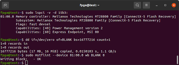
If the above fails, try overwriting the complete FLASH IC with a blank image:
sudo lspci -v -d 15b3:
dd if=/dev/zero of=BLANK.bin bs=4096 count=4096
sudo mstflint --device 01:00.0 wb BLANK.bin 0
Attempt to program the firmware using mstflint's Write Block (wb) command. The 25GbE SFP28 MT27808A0 MNV303212A-ADLT with 8GB of DDR4 is nicknamed Morse while the 100GbE QSFP MT28808A0 MNV303611A-EDLT is nicknamed MorseQ and its firmware is in MorseQ_FW. cd into the appropriate directory.
cd ~/Innova_2_Flex_Open_18_12/FW/Morse_FW/
sudo mstflint --device 01:00.0 wb fw-ConnectX5-rel-16_24_4020-MNV303212A-ADL_Ax.bin  0
Program the ConnectX-5 firmare a second time using mstflint's Write Image command:
sudo mstflint --allow_rom_change --device 01:00.0 --image fw-ConnectX5-rel-16_24_4020-MNV303212A-ADL_Ax.bin burn
Power cycle the Innova-2 system. Completely power off, wait 15 seconds, then power back on. Confirm the ConnectX-5 firmware has been updated.
sudo mst start
sudo mst status
sudo flint --device /dev/mst/mt525_pciconf0 query
If the above worked, proceed to update the GUID and MAC IDs.
If the above method of forcing Recovery Mode worked, you may skip this section. I have only needed an exact copy of the initial firmware that came with the board when preparing these notes. However, if you have the ability to read FLASH ICs then it is safer to have a copy.
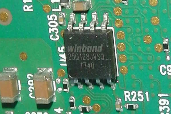
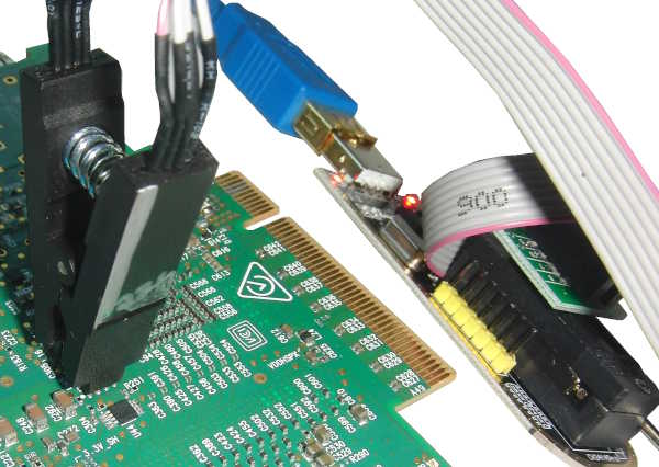
The ConnectX-5's FLASH IC is a 3V 128Mbit=16Mbyte W25Q128JVS. I was able to successfully program it using a CH341A Programmer. This is a dangerous procedure that can damage your Innova-2. Please do not make this your first attempt at FLASH IC programming. Consider a practice run on some other less important device or purchase a W25Q128JVS IC to test with.
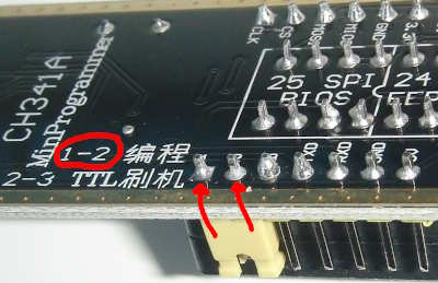
If you are using a CH341A Programmer, set the configuration jumper to default/SPI mode, 1-2.
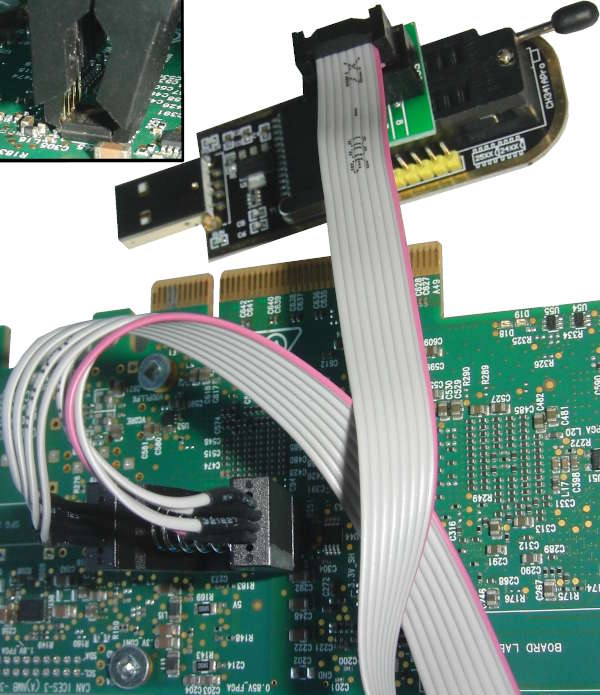
Please take ESD precautions seriously. Connect your 3.3V programmer to the W25Q128JVS. The Innova-2 should not be powered or plugged in.
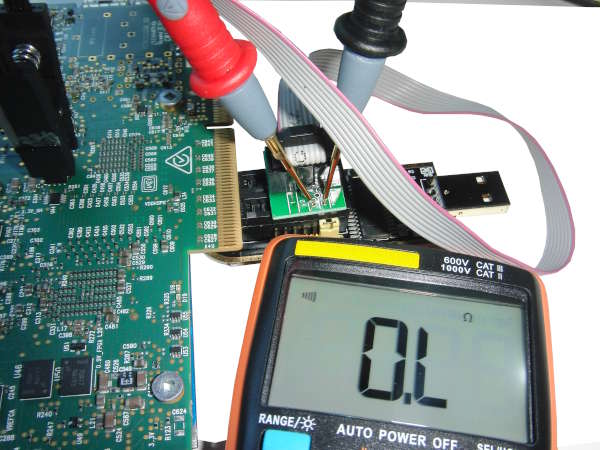
Confirm pin connections are independent. Pins 8, 7, and 3 (Vcc, Hold, and Write-Protect) are shorted together but all other pins are independent with respect to each other. Check every combination.
Confirm Programmer-to-FLASH IC connections. 1-to-1, 2-to-2, etc.
Abort if anything appears to be incorrect. If you are certain the programmer is connected properly and you accept the risks, plug the programmer into your system. The Innova-2 should not be powered or plugged in.
Use flashrom to test the Programmer-to-FLASH connection. The W25Q128.V should be found automatically by flashrom. If it is not found then there is something wrong with the IC and/or flashrom and/or connections.
sudo flashrom --programmer ch341a_spiUse flashrom to read the contents of the FLASH IC at least twice.
sudo flashrom --programmer ch341a_spi --read W25Q128save.bin
sudo flashrom --programmer ch341a_spi --read W25Q128save2.bin
Confirm FLASH IC reads are identical, similar to below. Inconsistent reads imply there is something wrong with the connection. If your programmer supports it, slow down the SPI Speed and try again.
sha256sum W25Q128save.bin W25Q128save2.binConfirm FLASH IC reads are sensible. Notice the ab cd ef 00 fa de 12 34 56 78 de ad in the first line of the header. An all-ones ff data read means the W25Q128 has been erased or was never programmed.
od -A x -t x1z -v W25Q128save.bin | headIf flashrom successfully detected the W25Q128.V and reads are consistent, then the requirement for sensible reads is a judgement call on your part.
Use flashrom to write the latest Innova-2 firmware to the W25Q128. This takes several minutes. The 25GbE SFP28 MNV303212A-ADLT with 8GB DDR4 is nicknamed Morse while the 40GbE/100GbE QSFP MNV303611A-EDLT without DDR memory is nicknamed MorseQ. cd into the appropriate directory.
cd ~/Innova_2_Flex_Open_18_12/FW/Morse_FW/
sudo flashrom --programmer ch341a_spi --write fw-ConnectX5-rel-16_24_4020-MNV303212A-ADL_Ax.bin
Power down your system. Wait a moment, then power back up.
Start Mellanox Software Tools (MST) and query the new firmware with flint.
sudo mst start
sudo mst status
sudo mst status -v
sudo flint --device /dev/mst/mt4119_pciconf0 query
If the GUID and MAC IDs are blank, you can use flint to set the values back to those from earlier. Note the 0x hex designator prepended to the values.
sudo flint --device /dev/mst/mt4119_pciconf0 -guid 0xc0dec0dec0dec0de -mac 0xc0dec0dec0de sg
sudo mlxfwreset --device /dev/mst/mt4119_pciconf0 reset
sudo flint --device /dev/mst/mt4119_pciconf0 query
Power down and restart your system.
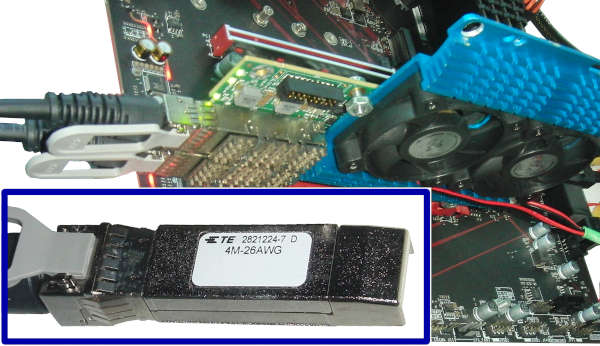
The network interfaces can be tested using 1G, 10G, or 25G SFP/SFP+/SFP28 modules and cables. The ConnectX-5 MT2x808 supports all three speeds. If you have the 100GbE QSFP MNV303611A-EDL variant of the Innova-2 it requires 40GbE or 100GbE QSFP equipment. I used a Direct-Attach Cable (DAC). Any DAC that is Mellanox or Cisco compatible should work.
Check that the cable is recognized.
sudo mst start
sudo mst cable add
sudo mlxcables
The Innova-2 interfaces show up as enp4s0f0 and enp4s0f1 or similar.
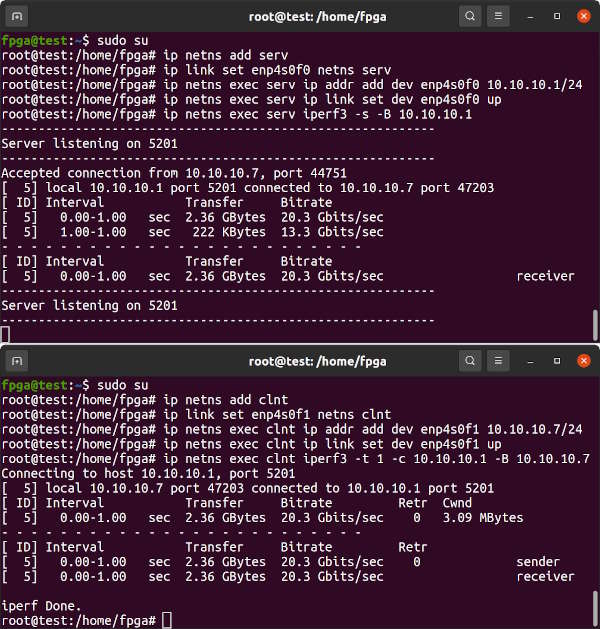
ip link show | grep enpTwo connected network interfaces on the same system can be tested by attaching each to its own namespace and then running iperf3 between them.
In one terminal, set up a Server namespace and attach one of the network interfaces to it.
sudo su
ip netns add serv
ip link set enp4s0f0 netns serv
ip netns exec serv ip addr add dev enp4s0f0 10.10.10.1/24
ip netns exec serv ip link set dev enp4s0f0 up
ip netns exec serv iperf3 -s -B 10.10.10.1
In a second terminal, set up a Client namespace and attach the other network interface to it. Then run iperf3.
sudo su
ip netns add clnt
ip link set enp4s0f1 netns clnt
ip netns exec clnt ip addr add dev enp4s0f1 10.10.10.7/24
ip netns exec clnt ip link set dev enp4s0f1 up
ip netns exec clnt iperf3 -t 1 -c 10.10.10.1 -B 10.10.10.7
Results should approach about 23Gbits/sec as there is some overhead. Change the -t 1 option to -t 10 for longer throughput testing.
In order for innova2_flex_app to program a User Image into the FPGA's configuration memory it must communicate with the Flex Image running in the FPGA. The Flex and Factory Images must get into FPGA Configuration Memory and reproduce the Memory Layout as pictured below. The innova2_flex_app is faster at programming a User Image than JTAG as the Flex Image provides a PCIe interface to the FPGA's Configuration Memory FLASH ICs. Refer to the Innova-2 User Guide for more info.
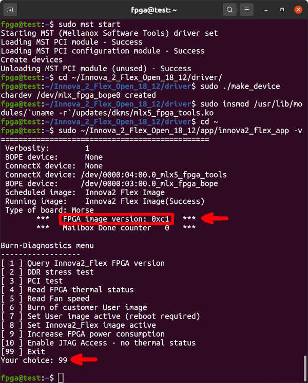
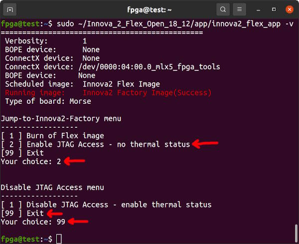
The Innova-2's ConnectX-5 firmware and FPGA Factory/Flex Image communicate to prevent JTAG access to the FPGA Configuration Memory outside of innova2_flex_app. JTAG must be enabled in innova2_flex_app before using JTAG. The Enable JTAG Access feature will reset to disabled after a system reboot. If your Innova-2 already has up-to-date Factory and Flex images that work with innova2_flex_app (notice the FPGA image version: 0xc1 below) then proceed to Loading User a Image. Press 99-Enter to exit innova2_flex_app.
sudo mst start
sudo mst status
sudo mst status -v
sudo flint -d /dev/mst/mt4119_pciconf0 q
cd ~/Innova_2_Flex_Open_18_12/driver/
sudo ./make_device
sudo insmod /usr/lib/modules/`uname -r`/updates/dkms/mlx5_fpga_tools.ko
lsmod | grep mlx
cd ~
sudo ~/Innova_2_Flex_Open_18_12/app/innova2_flex_app -v
If the FPGA Image is NOT Version 0xc1, choose option 10-enter to enable JTAG then 99-enter to exit.
Create configuration images that span the entire memory map as in the memory layout pictured earlier. The Innova_2_Flex_Open_18_12 package does not include configuration files with the binary images so everything gets written to address 0x00000000 which is incorrect. Create correct full memory images by copying data from the individual images into blank 64MB files. This should be done on the system running JTAG and requires a copy of Innova_2_Flex_Open_18_12 from earlier. The configuration data is split into primary and secondary parts between the two x4 FLASH ICs to double throughput to x8 during loading.
cd ~/Innova_2_Flex_Open_18_12/FPGA_image

ls -l ./Factory_image/morse_diagnostic_ku15p_bow_10g_v192_primary.bin
ls -l ./Flex_image/morse_diagnostic_ku15p_bow_10g_v193_primary.bin

dd if=/dev/zero of=completeimage0.bin bs=4096 count=67108864 iflag=count_bytes

dd if=./Factory_image/morse_diagnostic_ku15p_bow_10g_v192_primary.bin of=completeimage0.bin bs=4096 count=14532176 conv=notrunc iflag=count_bytes
dd if=./Flex_image/morse_diagnostic_ku15p_bow_10g_v193_primary.bin    of=completeimage0.bin bs=4096 seek=50331648 count=14382128 conv=notrunc oflag=seek_bytes iflag=count_bytes

sha256sum ./Factory_image/morse_diagnostic_ku15p_bow_10g_v192_primary.bin
dd if=completeimage0.bin bs=4096 count=14532176 iflag=count_bytes | sha256sum

sha256sum ./Flex_image/morse_diagnostic_ku15p_bow_10g_v193_primary.bin
dd if=completeimage0.bin bs=4096 skip=50331648 count=14382128 iflag=skip_bytes,count_bytes | sha256sum

ls -l ./Factory_image/morse_diagnostic_ku15p_bow_10g_v192_secondary.bin
ls -l ./Flex_image/morse_diagnostic_ku15p_bow_10g_v193_secondary.bin

dd if=/dev/zero of=completeimage1.bin bs=4096 count=67108864 iflag=count_bytes

dd if=./Factory_image/morse_diagnostic_ku15p_bow_10g_v192_secondary.bin of=completeimage1.bin bs=4096 count=14532176 conv=notrunc iflag=count_bytes
dd if=./Flex_image/morse_diagnostic_ku15p_bow_10g_v193_secondary.bin    of=completeimage1.bin bs=4096 seek=50331648 count=14382128 conv=notrunc oflag=seek_bytes iflag=count_bytes

sha256sum ./Factory_image/morse_diagnostic_ku15p_bow_10g_v192_secondary.bin
dd if=completeimage1.bin bs=4096 count=14532176 iflag=count_bytes | sha256sum

sha256sum ./Flex_image/morse_diagnostic_ku15p_bow_10g_v193_secondary.bin
dd if=completeimage1.bin bs=4096 skip=50331648 count=14382128 iflag=skip_bytes,count_bytes | sha256sum

echo d1fcfa0315c302a4a84c45abeae66bb8365757802f57e8979e5a46a593883340
sha256sum completeimage0.bin
echo bae7da6f6426445ca5a0f6eb8786a2e6c4c8b591599506b306ba109a634efedc
sha256sum completeimage1.bin
Confirm the memory images were generated correctly. These checksums are only valid for files generated from Innova_2_Flex_Open_18_12.tar.gz.
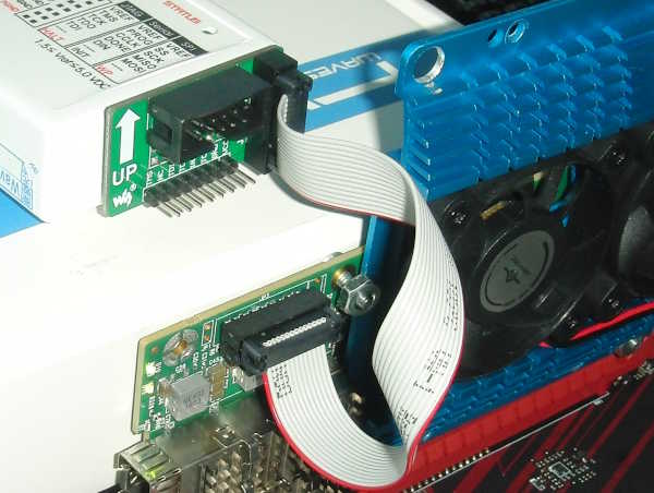
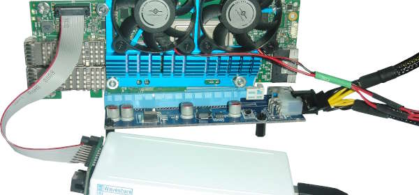
sha256sum completeimage0.bin completeimage1.binConnect your Xilinx-Compatible 1.8V JTAG Adapter to your Innova-2 but power the Innova-2 from a second computer or using a Powered External PCIe Extender. Running JTAG from the system with the Innova-2 may cause undefined behaviour. If JTAG halts the FPGA it will disappear off the PCIe bus and crash Ubuntu.
A Powered PCIe Riser/Extender is another option for powering the Innova-2 while JTAG programming.
Start Vivado Hardware Manager. Any recent version of Vivado Lab Edition or full Vivado is enough for this task.
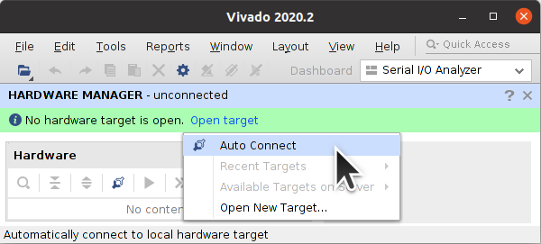
Start a Connection, Open Target -> Auto Connect
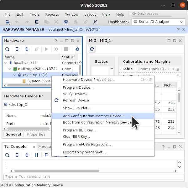
Right-click on xcku15p_0 and select Add Configuration Memory Device ...
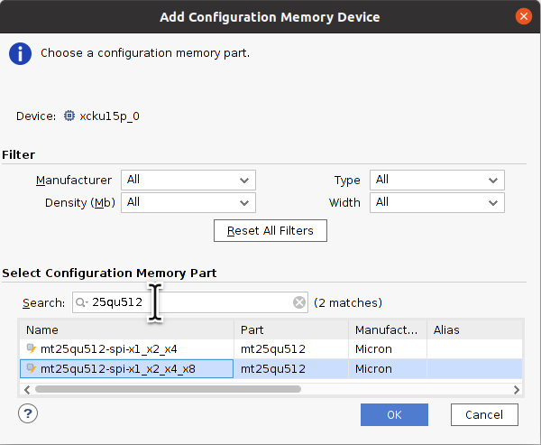
Select mt25qu512-spi-x1_x2_x4_x8.
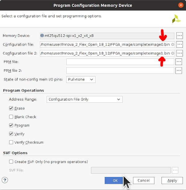
Program the complete memory images.
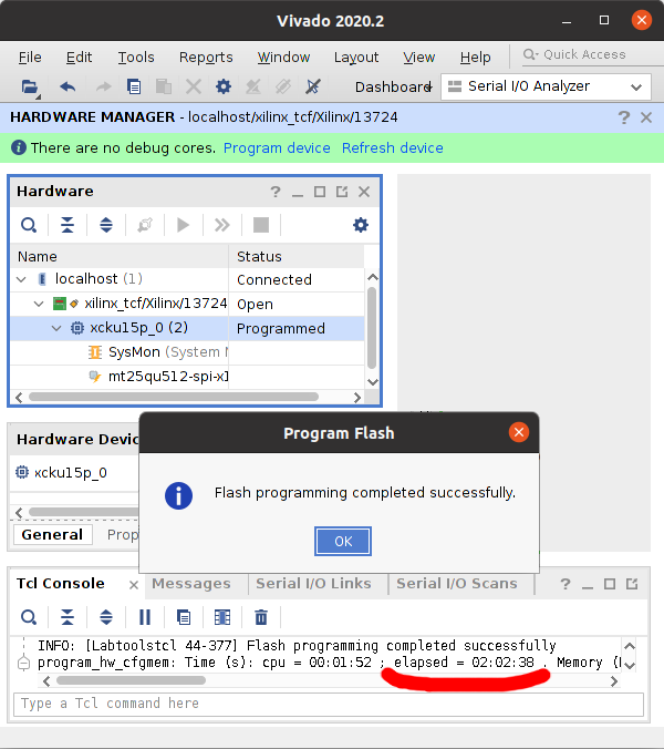
Once programming finishes, which can take hours, power everything down and disconnect the JTAG adapter.
Reboot and run innova2_flex_app to disable JTAG access, option 1, so that innova2_flex_app can program User Images. Reboot again.
sudo mst start
sudo mst status
sudo mst status -v
sudo flint -d /dev/mst/mt4119_pciconf0 q
cd ~/Innova_2_Flex_Open_18_12/driver/
sudo ./make_device
sudo insmod /usr/lib/modules/`uname -r`/updates/dkms/mlx5_fpga_tools.ko
lsmod | grep mlx
cd ~
sudo ~/Innova_2_Flex_Open_18_12/app/innova2_flex_app -v

sudo rebootThe process of enabling the Flex Image, rebooting, programming, enabling the User Image, then rebooting takes approximately 10 minutes each time you update your User Image.
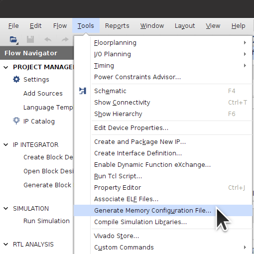
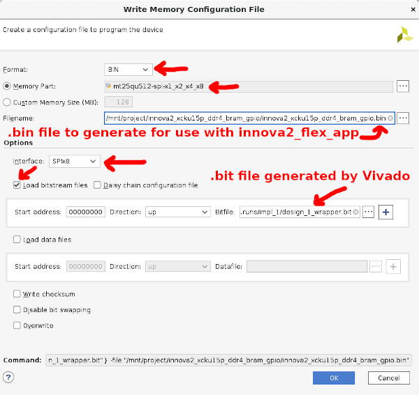
These instructions include a link to a bitstream for a working demo. Otherwise, after Vivado generates a programming Bitstream for your design, run Generate Memory Configuration File:
Select bin, mt25qu512_x1_x2_x4_x8, SPIx8, Load bitstream files, and a location and name for the output binary files. The bitstream will end up, for example, in the DESIGN_NAME/DESIGN_NAME.runs/impl_1 subdirectory as SOMETHING.bit. Vivado will add the _primary.bin and _secondary.bin extensions as the Innova-2 uses dual MT25QU512 FLASH ICs in x8 for high speed programming.
Before using innova2_flex_app for programming, disconnect any JTAG adapter (unplug its USB cable).
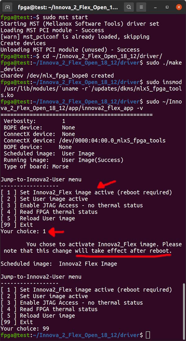
The Innova-2 Flex Image must be activated to allow innova2_flex_app to program the FPGA's Configuration Memory. Run the innova2_flex_app and choose option 1-enter then 99-enter to enable the Flex Image. Reboot your system for the change to take effect. This is the start of a programming cycle which is: disable JTAG and schedule the Flex image, reboot, program with innova2_flex_app, reboot, and then test your loaded bitstream.
sudo mst start
cd ~/Innova_2_Flex_Open_18_12/driver/
sudo ./make_device
sudo insmod /usr/lib/modules/`uname -r`/updates/dkms/mlx5_fpga_tools.ko

sudo ~/Innova_2_Flex_Open_18_12/app/innova2_flex_app -v

sudo reboot
After rebooting the Flex Image should be active. Look for Class 2000: Mellanox Technologies Innova-2 Flex Burn image or similar.
lspci | grep -i Mellanox
Start MST and load FPGA Tool modules.
cd ~
sudo mst start
sudo mst status
sudo mst status -v
sudo flint -d /dev/mst/mt4119_pciconf0 q
cd ~/Innova_2_Flex_Open_18_12/driver/
sudo ./make_device
sudo insmod /usr/lib/modules/`uname -r`/updates/dkms/mlx5_fpga_tools.ko
cd ~
For board testing, the following command will clone the innova2_xdma_demo project which includes bitstream binaries for programming to the FPGA. Otherwise, cd into your own project directory.
git clone --depth=1 https://github.com/mwrnd/innova2_xdma_demo.git
cd innova2_xdma_demo
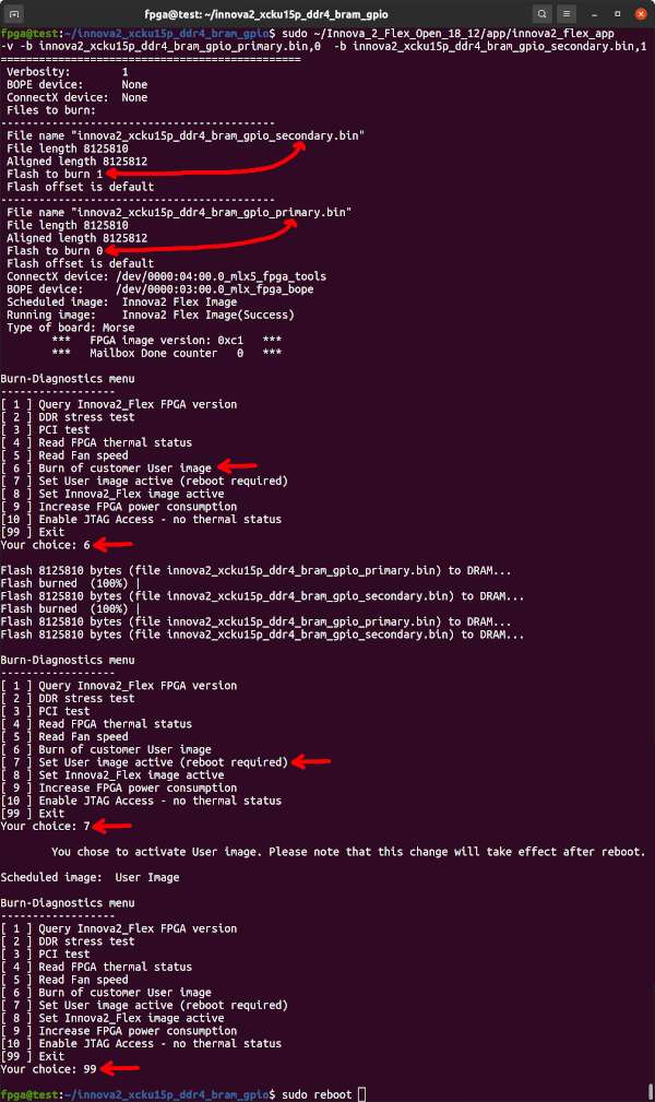
Run innova2_flex_app with appropriate -b commands to program a design into the FPGA. Note the _primary.bin,0 and _secondary.bin,1. Choose option 6-enter to program the design, then 7-enter to set the User Image as active, then 99-enter to exit.
sudo ~/Innova_2_Flex_Open_18_12/app/innova2_flex_app -v \
  -b innova2_xdma_demo_primary.bin,0                    \
  -b innova2_xdma_demo_secondary.bin,1
Reboot your system.
sudo reboot
After programming the bitstream and rebooting, the design should show up as Memory controller: Xilinx Corporation Device 9038. It shows up at PCIe Bus Address 03:00 for me.
lspci -d 10ee:
The following lspci commands list all Mellanox and Xilinx devices and show their relation.
lspci -nn | grep "Mellanox\|Xilinx"
lspci -tv | grep "0000\|Mellanox\|Xilinx"
The FPGA is attached to a PCIe Bridge (02:08.0), as are the two Ethernet Controllers (02:10.0).
01:00.0 PCI bridge [0604]: Mellanox Technologies MT28800 Family [ConnectX-5 PCIe Bridge] [15b3:1974]
02:08.0 PCI bridge [0604]: Mellanox Technologies MT28800 Family [ConnectX-5 PCIe Bridge] [15b3:1974]
02:10.0 PCI bridge [0604]: Mellanox Technologies MT28800 Family [ConnectX-5 PCIe Bridge] [15b3:1974]
03:00.0 Memory controller [0580]: Xilinx Corporation Device [10ee:9038]
04:00.0 Ethernet controller [0200]: Mellanox Technologies MT27800 Family [ConnectX-5] [15b3:1017]
04:00.1 Ethernet controller [0200]: Mellanox Technologies MT27800 Family [ConnectX-5] [15b3:1017]

-[0000:00]-+-00.0  Intel Corporation Device 3e0f
           +-1d.0-[01-04]----00.0-[02-04]--+-08.0-[03]----00.0  Xilinx Corporation Device 9038
           |                               \-10.0-[04]--+-00.0  Mellanox Technologies MT27800 Family [ConnectX-5]
           |                                            \-00.1  Mellanox Technologies MT27800 Family [ConnectX-5]
The current PCIe Link status is useful. This is the FPGA to ConnectX-5 PCIe Bridge link.
sudo lspci -nnvd 10ee: ; sudo lspci -nnvvd 10ee: | grep Lnk
dmesg | grep -i xdma provides details on how Xilinx's PCIe XDMA driver has loaded.
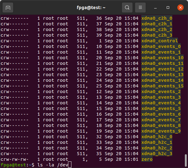
The XDMA Driver (dma_ip_drivers) creates character device files that are write-only and read-only, /dev/xdma0_h2c_0 and /dev/xdma0_c2h_0 respectively. They allow direct access to the FPGA design's AXI Bus. To read from an AXI Block at address 0x80000000 you would read from address 0x80000000 of the /dev/xdma0_c2h_0 (Card-to-Host) file. To write you would write to the appropriate address of /dev/xdma0_h2c_0 (Host-to-Card).
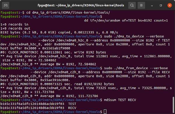
The commands below generate 8kb of random data then use the utilities from dma_ip_drivers to send the data to the M_AXI BRAM Controller Block in the XCKU15P, then read it back and confirm the data is identical. The address of the BRAM Controller is 0x80000000 in the innova2_xdma_demo project.
cd dma_ip_drivers/XDMA/linux-kernel/tools/
dd if=/dev/urandom of=TEST bs=8192 count=1
sudo ./dma_to_device   --verbose --device /dev/xdma0_h2c_0 --address 0x80000000 --size 8192  -f    TEST
sudo ./dma_from_device --verbose --device /dev/xdma0_c2h_0 --address 0x80000000 --size 8192 --file RECV
md5sum TEST RECVThe AXI Blocks can also be accessed using dd. dd requires numbers in Base-10 so you can use printf to convert from the hex address, 0x80000000=2147483648. count=1 as this is a single transfer to address 0x80000000 so the lseek address should not be reset.
dd if=/dev/urandom of=TEST bs=8192 count=256
printf "%d\n" 0x80000000
sudo dd if=TEST of=/dev/xdma0_h2c_0 bs=2097152 count=1 seek=2147483648 oflag=seek_bytes
sudo dd if=/dev/xdma0_c2h_0 of=RECV bs=2097152 count=1 skip=2147483648 iflag=skip_bytes
md5sum TEST RECV
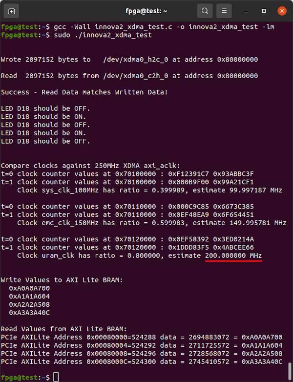
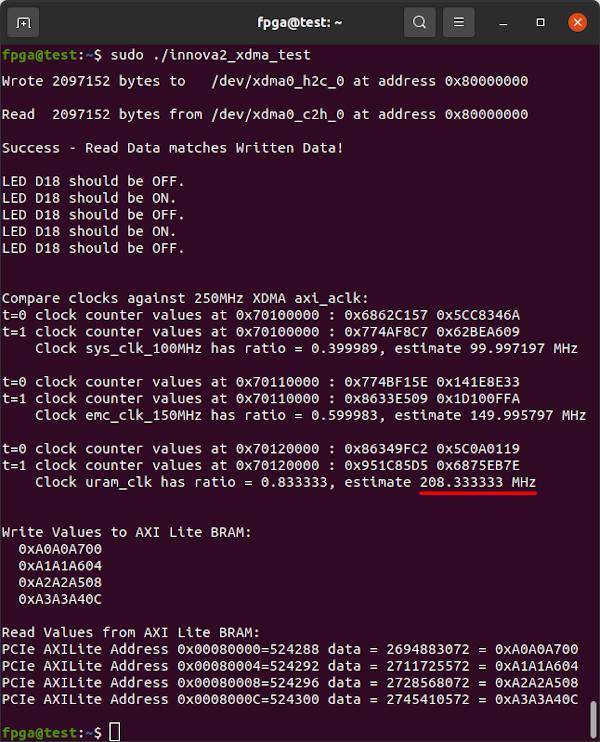
innova2_xdma_test.c is a simple program that demonstrates XDMA communication in C. It uses pread and pwrite to communicate with AXI Blocks. read and write plus lseek can also be used.
gcc -Wall innova2_xdma_test.c -o innova2_xdma_test -lm
sudo ./innova2_xdma_test
The design allows for measuring the frequency of various connected clocks by comparing them to the 250MHz XDMA axi_aclk.
If the above works then great! Your Innova-2 has a working FPGA with PCIe. The innova2_xdma_demo project page has more testing.
Designs with identical XDMA Block configurations can be updated using JTAG. Bitstream update over JTAG is only retained for as long as the board is powered but takes under 1 minute which is less than the approximately 10 required when updating the configuration Flash memory. Very useful when iterating designs.
The host system for the Innova-2 needs to support PCIe Hotplug for Bitstream update to work with PCIe. Confirm your computer's motherboard chipset and BIOS support PCIe hotplug. Check your Linux kernel by looking for CONFIG_HOTPLUG_PCI_PCIE=y in its /boot/config-??? configuration file.
cat /boot/config-5.8.0-43-generic | grep -i pci | grep -i hotplug
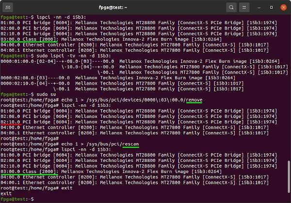
Find your design on the PCIe bus address, the 03 below, and remove it. Then rescan the PCIe bus to confirm it shows up again.
lspci -nn
sudo lspci -tv -nn

sudo su
echo 1 > /sys/bus/pci/devices/0000\:03\:00.0/remove
lspci -nn
echo 1 > /sys/bus/pci/rescan
lspci -nn
exit
If remove and rescan works, run innova2_flex_app and choose option 3-Enter to enable JTAG Access then 99-Enter to exit. The Enable JTAG Access feature will reset to disabled after a system reboot.
sudo mst start
cd ~/Innova_2_Flex_Open_18_12/driver/
sudo ./make_device
cd ~
sudo insmod /usr/lib/modules/5.8.0-43-generic/updates/dkms/mlx5_fpga_tools.ko
sudo ~/Innova_2_Flex_Open_18_12/app/innova2_flex_app
Confirm the XDMA device is present then remove it from the PCIe bus and disconnect it from its PCIe Bridge. The ConnectX-5 PCIe Bridge for the FPGA on the Innova-2 is sub-device 08, function 0, :08.0. It shows up as PCIe device 02 for me.
lspci  |  grep -i "Xilinx\|Mellanox"

sudo su
lspci -nn -d 10ee:
echo 1 > /sys/bus/pci/devices/0000\:03\:00.0/remove
lspci -nn -d 10ee:

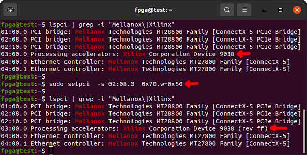
setpci  -s 02:08.0  0x70.w=0x50
Confirm checksum of the Bitstream.
md5sum xdma_wrapper_208MHz.bit
echo b7feb55f6d84bbf4ed96b7f9c791c5c8 should be the MD5 checksum of xdma_wrapper_208MHz.bit
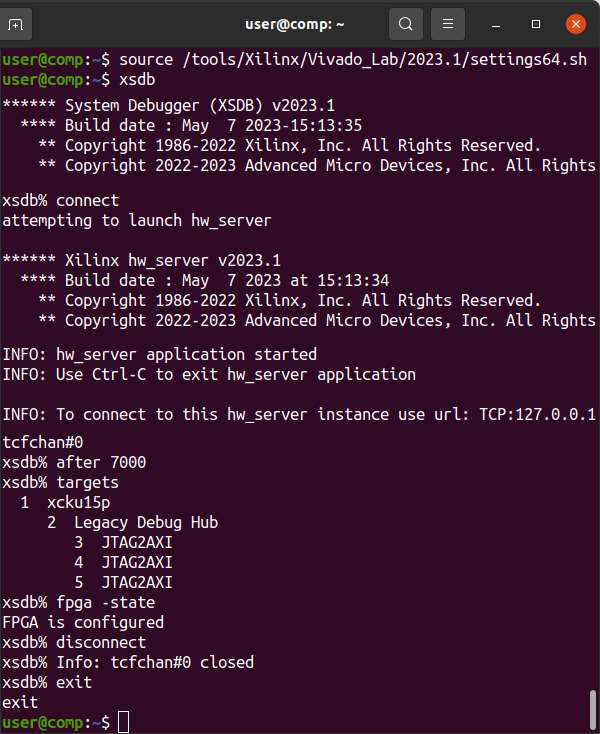
Load your Vivado or Vivado Lab settings64.sh and start xsdb. The after 7000 command waits 7 seconds for Xilinx-Compatible JTAG adapters based on the FX2 to update their firmware and needs to happen every time the adapter is powered.
source /tools/Xilinx/Vivado_Lab/2023.1/settings64.sh
xsdb
connect
after 7000
targets
target 1
fpga -state
fpga xdma_wrapper_208MHz.bit
fpga -state
disconnect
exit
Reconnect the FPGA to the PCIe Bridge and rescan the PCIe bus.
setpci  -s 02:08.0  0x70.w=0x40
echo 1 > /sys/bus/pci/rescan
exit
The PCIe device should return with the same settings as before.
sudo lspci -nnvd 10ee: ; sudo lspci -nnvvd 10ee: | grep Lnk
dmesg | grep -i xdma will inform you if the XDMA driver has loaded correctly.
Run the test program. It should now show 208.333333MHz as an estimate for uram_clk.
sudo ./innova2_xdma_test
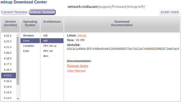
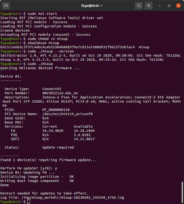
If you are experiencing issues with your Innova-2 or require PXE Boot capability, explore upgrading the ConnectX-5 using the mlxup utility. Check out the mlxup User Guide. The latest version to support the Innova-2 is 4.15.2 and will upgrade your ConnectX-5 firmware to 16.28.2006 and PXE Boot 3.6.0102.
cd ~
wget https://www.mellanox.com/downloads/firmware/mlxup/4.15.2/SFX/linux_x64/mlxup
echo b3c1c1e6b5c3f37c46bc6ceb319d4b888379a7c813a7e08d931f962572eb7ac4 should be the SHA256 checksum
sha256sum mlxup
sudo mst start
sudo chmod +x mlxup
sudo ./mlxup --version
sudo ./mlxup
The latest firmware directy downloadable from Nvidia/Mellanox is 16.26.4012 which is older than the version included with mlxup 4.15.2
If the PCIe Bridge partially shows up in lspci, the W25Q128JVS FLASH IC has failed or is written incorrectly.
sudo lspci | grep -i mellanoxShut down your Innova2 system and unplug power, wait a minute, then power the system back up. If that fails, Confirm Mellanox OFED Installed Successfully. If all else fails, try re-programming the W25Q128JVS.
The Factory Image (FLASH IC Address 0x00000000) is Running even though the Flex Image (FLASH IC Address 0x03000000) is the Scheduled image. This implies there is a fault with the Flex Image, or it was overwritten, or a User Image was written to address 0x00000000 by mistake, instead of 0x01000000. The Innova2 Flex App will not be able to program a User Image into the FPGA Configuration Memory.
Enable JTAG Access and program the FPGA Configuration Memory to factory default.
Confirm the ConnectX and BOPE Devices are present when running innova2_flex_app -v.
The ConnectX device is created by running insmod /usr/lib/modules/5.8.0-43-generic/updates/dkms/mlx5_fpga_tools.ko
The BOPE device is created by running ~/Innova_2_Flex_Open_18_12/driver/make_device. BOPE will fail to load if the FPGA Image is not compatible with your innova2_flex_app version. Program the FPGA.
cd ~
sudo mst start
sudo mst status
sudo mst status -v
sudo flint -d /dev/mst/mt4119_pciconf0 q
cd ~/Innova_2_Flex_Open_18_12/driver/
sudo ./make_device
sudo insmod /usr/lib/modules/`uname -r`/updates/dkms/mlx5_fpga_tools.ko
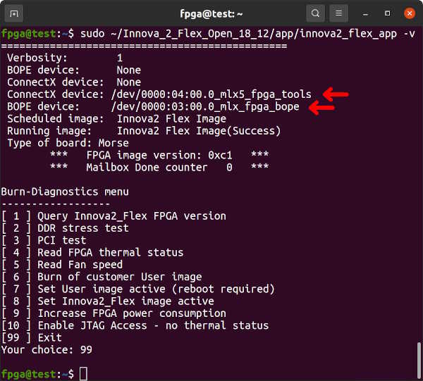
If you run sudo ~/Innova_2_Flex_Open_18_12/app/innova2_flex_app -v and do not see a BOPE and ConnectX device:
===============================================
 Verbosity:        1
 BOPE device:      None
 ConnectX device:  None
Cannot find appropriate ConnectX device
The following commands must be run after each reboot to reinstall the BOPE and ConnectX devices if you intend to program the FPGA.
sudo mst start
sudo mst status
sudo mst status -v
sudo flint -d /dev/mst/mt4119_pciconf0 q
cd ~/Innova_2_Flex_Open_18_12/driver/
sudo ./make_device
sudo insmod /usr/lib/modules/`uname -r`/updates/dkms/mlx5_fpga_tools.ko
lsmod | grep mlx
cd ~
sudo ~/Innova_2_Flex_Open_18_12/app/innova2_flex_app -v
The mlx5_fpga_tools module creates the ConnectX device:
sudo insmod /usr/lib/modules/`uname -r`/updates/dkms/mlx5_fpga_tools.ko
sudo ~/Innova_2_Flex_Open_18_12/app/innova2_flex_app -v
===============================================
 Verbosity:        1
 BOPE device:      None
 ConnectX device:  None
 ConnectX device: /dev/0000:04:00.0_mlx5_fpga_tools
 BOPE device:     None
 Scheduled image:  Innova2 Flex Image
 Running image:    User Image(Success)
 Type of board: Morse

Jump-to-Innova2-User menu
------------------
[ 1 ] Set Innova2_Flex image active (reboot required)
[ 2 ] Set User image active
[ 3 ] Enable JTAG Access - no thermal status
[ 4 ] Read FPGA thermal status
[ 5 ] Reload User image
[99 ] Exit
Your choice: 99
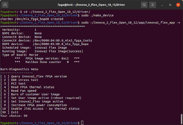
The make_device utility creates the BOPE device:
cd ~/Innova_2_Flex_Open_18_12/driver/
sudo ./make_device
sudo ~/Innova_2_Flex_Open_18_12/app/innova2_flex_app -v
===============================================
 Verbosity:        1
 BOPE device:      None
 ConnectX device:  None
 ConnectX device: /dev/0000:04:00.0_mlx5_fpga_tools
 BOPE device:     /dev/0000:03:00.0_mlx_fpga_bope
 Scheduled image:  Innova2 Flex Image
 Running image:    Innova2 Flex Image(Success)
 Type of board: Morse
	***   FPGA image version: 0xc1   ***
	***   Mailbox Done counter   0   ***

Burn-Diagnostics menu
------------------
[ 1 ] Query Innova2_Flex FPGA version
[ 2 ] DDR stress test
[ 3 ] PCI test
[ 4 ] Read FPGA thermal status
[ 5 ] Read Fan speed
[ 6 ] Burn of customer User image
[ 7 ] Set User image active (reboot required)
[ 8 ] Set Innova2_Flex image active
[ 9 ] Increase FPGA power consumption
[10 ] Enable JTAG Access - no thermal status
[99 ] Exit
Your choice: 99
Once both BOPE and ConnectX devices exist and the Flex Image is the Active Image, you can run innova2_flex_app with appropriate -b commands to program a design into the FPGA. Note the _primary.bin,0 and _secondary.bin,1. Choose option 6-enter to program the design, then 7-enter to set the User Image as active, then 99-enter to exit.
sudo ~/Innova_2_Flex_Open_18_12/app/innova2_flex_app -v \
  -b innova2_xcku15p_ddr4_bram_gpio_primary.bin,0       \
-b innova2_xcku15p_ddr4_bram_gpio_secondary.bin,1If you attempt to send data to the DDR4 address but get write file: Unknown error 512 it means DDR4 did not initialize properly or you are attempting to communicate with the wrong address. The innova2_xcku15p_ddr4_bram_gpio project has DDR4 at address 0x0 but if you made any changes confirm in the Vivado Block Design Address Editor that it is still 0x0. The DDR4 IP Block does not allow reading from memory that has not yet been written to. Test with a write then a read. See the Innova-2 DDR4 Troubleshooting project for DDR4 hardware debugging help.
cd ~/dma_ip_drivers/XDMA/linux-kernel/tools/
dd if=/dev/urandom bs=1 count=8192 of=TEST
sudo ./dma_to_device   --verbose --device /dev/xdma0_h2c_0 --address 0x0 --size 8192  -f    TEST
sudo ./dma_from_device --verbose --device /dev/xdma0_c2h_0 --address 0x0 --size 8192 --file RECV
md5sum TEST RECVIf Vivado finishes Configuration Memory Programming in under a minute with a [Labtools 27-3165] End of startup status: Low error, it has not programmed anything. This occurs when the Innova-2 still has control over JTAG.
Enable JTAG Access before attempting JTAG programming. 10-Enter then 99-Enter in innova2_flex_app. The Enable JTAG Access feature will reset to disabled after a system reboot.
sudo mst start
sudo mst status
sudo mst status -v
sudo flint -d /dev/mst/mt4119_pciconf0 q
cd ~/Innova_2_Flex_Open_18_12/driver/
sudo ./make_device
sudo insmod /usr/lib/modules/`uname -r`/updates/dkms/mlx5_fpga_tools.ko
lsmod | grep mlx

cd ~
sudo ~/Innova_2_Flex_Open_18_12/app/innova2_flex_app -vConfirm your JTAG Adapter works by trying it with a different FPGA board. Confirm it operates at 1.8V. The ConnectX-5 interacts with the FPGA's JTAG pins so try enabling JTAG. If you suspect a hardware fault, I found some JTAG-related components.
innova2_flex_app will get stuck on Erasing flash ( 0%) if a JTAG Adapter has not released control of JTAG signals. Disconnect the JTAG Adapter from USB and perform a cold reboot of the Innova-2 system.
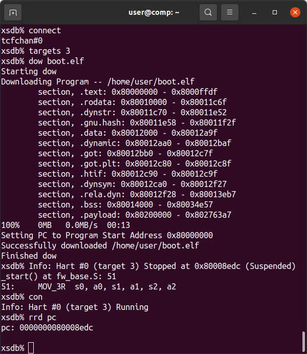
If you are attempting to use xsdb to load a program into a Soft Processor Core (RISC-V, MicroBlaze) using JTAG and encounter Memory Write Errors:
...
 83%    0MB   0.0MB/s  00:02 ETA
Failed to download /home/user/vivado-risc-v/workspace/boot.elf
Memory write error at 0x80226400. Debug Transport Module: data corruption (ID)
xsdb% Info: Hart #0 (target 3) Running (FPGA reprogrammed, wait for debugger resync)
...
JTAG Access must be enabled before attempting to download programs to a Soft Processor Core in the FPGA using JTAG. 3-Enter then 99-Enter in innova2_flex_app.
xsdb then works:
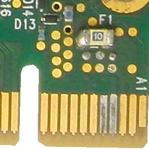
While testing voltages next to the SFP connectors on a powered board my multimeter lead slipped and I shorted the 12V rail. I replaced fuse F1 with a Bel Fuse 0685P9100-01 Fast 1206 10A SMT fuse and the board was saved. I got lucky. A blown fuse is either a simple fix or a sign of catastrophic failure.
The board is well designed with all voltage rails exposed on test points. Carefully measure each one.
If you are experiencing PCIe communication problems, flip this setting in your BIOS.
It should have no effect when running a 64-Bit OS but sometimes it does. Flip this setting in your BIOS if you have any problems or throughput bandwidth seems low.
UrJTAG is a low-level tool for communicating with JTAG devices. It supports Xilinx Platform Cable USB II adapters and clones. Main use is EXTEST pin toggling although it is theoretically possible to program the FPGA using an SVF file generated from the Vivado Tcl Console.
cd ~
wget https://versaweb.dl.sourceforge.net/project/urjtag/urjtag/2021.03/urjtag-2021.03.tar.xz
sha256sum urjtag-2021.03.tar.xz
echo b0a2eaa245513af096dc4d770109832335c694c6c12aa5e92fefae8685416f1c should be the SHA256 Checksum
tar -xvf urjtag-2021.03.tar.xz
cd urjtag-2021.03/
./configure
make
sudo make install
sudo ldconfigXilinx's Kintex Ultrascale+ BSDL Files include STD_1149_6_2003.all Advanced I/O Testing definitions that UrJTAG's bsdl2jtag cannot process. They must therefore be removed. The included xcku15p_ffve1517_bsd.patch is a patch to Xilinx's BSDL file for the 1517-pin XCKU15P that removes incompatible definitions. The resulting file is then processed with bsdl2jtag to produce the included xcku15p_ffve1517.jtag file.
From the directory containing xcku15p_ffve1517.jtag run the following commands which create PART and STEPPINGS files for the XCKU15P. These commands assume UrJTAG installed support files to the default /usr/local/share/ directory. Values were found by running the UrJTAG detect command which reads the Device Id from the JTAG chain. First 4 bits (0001) are the STEPPING, next 16 bits (0100101001010110) are the PART, last 12 bits (000010010011) are the MANUFACTURER.
sudo su
echo "# Kintex Ultrascale+ (XCKUxxP)" >>/usr/local/share/urjtag/xilinx/PARTS
echo "0100101001010110        xcku15p_1517   xcku15p_ffve1517" >>/usr/local/share/urjtag/xilinx/PARTS
mkdir /usr/local/share/urjtag/xilinx/xcku15p_1517
touch /usr/local/share/urjtag/xilinx/xcku15p_1517/STEPPINGS
echo "0000 xcku15p_1517 0" >>/usr/local/share/urjtag/xilinx/xcku15p_1517/STEPPINGS
echo "0001 xcku15p_1517 1" >>/usr/local/share/urjtag/xilinx/xcku15p_1517/STEPPINGS
cp xcku15p_ffve1517.jtag /usr/local/share/urjtag/xilinx/xcku15p_1517/xcku15p_1517
exitJTAG Communication is controlled by the ConnectX-5 on the Innova-2. Enable JTAG Access to the FPGA using innova2_flex_app. The Enable JTAG Access feature will reset to disabled after a system reboot.
sudo mst start
sudo mst status
sudo mst status -v
sudo flint -d /dev/mst/mt4119_pciconf0 q
cd ~/Innova_2_Flex_Open_18_12/driver/
sudo ./make_device
sudo insmod /usr/lib/modules/`uname -r`/updates/dkms/mlx5_fpga_tools.ko
lsmod | grep mlx
cd ~
sudo ~/Innova_2_Flex_Open_18_12/app/innova2_flex_app -vlspci | grep -i Mellanox shows all connected Mellanox PCIe devices. The PCIe Bridge on the Innova-2 is device 08, function 0, :08.0. In the example below it shows up with Bus ID 02. Disable the FPGA-to-PCIe connection so that JTAG does not interfere with the PCIe bus. Notice the (rev ff) on the Xilinx device after disconnection.
sudo setpci -s 02:08.0 0x70.w=0x50It can later be re-enabled with the following command or a cold reboot.
sudo setpci -s 02:08.0 0x70.w=0x40Connect your JTAG Adapter to the Innova-2. If you are using a Platform Cable USB II compatible adapter it will show up under lsusb as 03fd:0013 Xilinx, Inc. In this state it cannot be used for JTAG.
Load your Vivado or Vivado Lab settings64.sh and start xsdb. The after 7000 command waits 7 seconds for Xilinx-Compatible JTAG adapters based on the FX2 to update their firmware and needs to happen every time the adapter is powered.
source /tools/Xilinx/Vivado_Lab/2023.1/settings64.sh
xsdb
connect
after 7000
targets
fpga -state
disconnect
exit
lsusb should now show 03fd:0008 Xilinx, Inc. Platform Cable USB II. The JTAG adapter is now ready to be used by UrJTAG.
sudo jtag to start UrJTAG with access to USB. You should see the jtag> command prompt. A JTAG Overview may be helpful before you begin.
cable xpc_ext selects the Xilinx Platform Cable, external JTAG chain
detect finds all devices in the JTAG chain
print chain prints all devices in the JTAG chain
part 0 selects the first JTAG part for communication. Good practise to always make this explicit.
instruction EXTEST select the External Test Function
shift ir shifts EXTEST into the JTAG Instruction Register to put the device into EXTEST mode
shift dr shifts the Data Register containing all pin states into UrJTAG memory
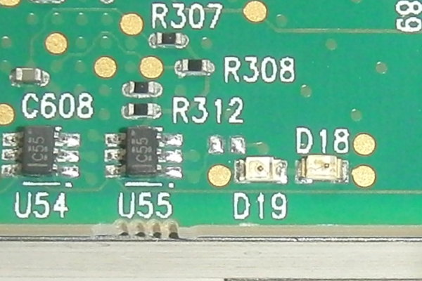
get signal IO_A6 displays the value of pin A6 (the inverted D19 LED) from the Data Register (1 = off)
get signal IO_B6 displays the value of pin B6 (the inverted D18 LED) from the Data Register (1 = off)
set signal IO_A6 out 0 sets pin A6 to output 0 in the Data Register in UrJTAG memory
shift dr shifts the Data Register out onto the device which should light up the D19 LED (0 = on)
set signal IO_B6 out 0 sets pin B6 to output 0 in the Data Register in UrJTAG memory
shift dr shifts the Data Register out onto the device which should light up the D18 LED (0 = on)
get signal IO_A6 displays the value of pin A6 from the last Data Register shift (0 = on)
get signal IO_B6 displays the value of pin B6 from the last Data Register shift (1=off is an error)
shift dr shifts the Data Register from the device into UrJTAG memory
get signal IO_B6 displays the value of pin B6 from the last Data Register shift (0=on is correct)
reset resets the JTAG chain and enters Bypass Mode
quit exits UrJTAG
If your DDR4-based design does not meet timing requirements:
Then slow down the DDR4:
If all goes well your design will meet timing requirements:
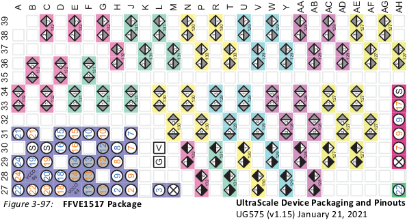
Taken from ug575 UltraScale+ Device Packaging Pinouts.
PCIe connections are on Quads 127 and 128 which are GTY Transceivers X0Y0-to-X0Y7. OpenCAPI connections are on Quads 131 and 132 which are GTY Transceivers X0Y16-to-X0Y23.
LEDs D18 and D19 are connected to pins B6 and A6, respectively, in Bank 90 of the XCKU15P.
dmesg | grep -i xdma will show you whether the Xilinx XDMA driver from dma_ip_drivers successully loaded for a PCIe-based FPGA design.
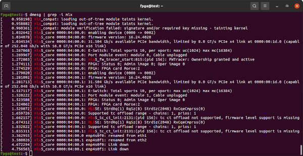
dmesg | grep -i mlx will show you whether the Mellanox OFED drivers successully loaded for the ConnectX-5.
sudo lspci -tv | grep "Mellanox\|Xilinx" displays a tree view of the PCIe bus.
- Nvidia Mellanox Innova-2 Flex Open Programmable SmartNIC
- Mellanox OFED Drivers
- Innova-2 Flex User Guide
- Lenovo sells the Innova-2 as the Lenovo 4XC7A16683.
- Lenovo Innova-2 Product Page
- Lenovo Version of User Guide
- Original Constraints XDC File(Archive)
- Xilinx XDMA Support
- Xilinx QDMA Support
- OpenCAPI Open Source Projects
- OpenCAPI Presentation mentions the Innova-2
- OpenCAPI3.0 Reference Design has no Innova-2 support
- OpenCAPI Pinout
- OpenCAPI OpenPower Advanced Accelerator Adapter Electro-Mechanical Specification
- OpenCAPI SlimSAS Connector U10-J074-24 or U10-K274-26
- SlimSAS SFF-8654 8i 85-Ohm Cable is required for OpenCAPI. A 3M 8ES8-1DF21 Cable(Datasheet) is the most reliable cable I have found.
- SocketDirect is an example of OpenCAPI use.
- The XCKU15P is an XCZU19 with its Processing System (PS) disabled
- DDR4 Memory ICS are MT40A1G16KNR-075 x16 Twin Die with D9WFR FBGA Code
- FPGA Configuration is stored in paired MT25QU512 FLASH ICs with RW193 FBGA Code
- MNV303212A-ADIT and MNV303212A-ADAT are 4GB (D9TBK FBGA Code) variants of the Innova-2 which have some caveats to their use
- MNV303611A-EDLT is a variant of the Innova-2 with 40GbE/100GbE QSFP connectors but no DDR4. Its codename is
MorseQ. - MNV303212A-ADLT and MNV303611A-EDLT EOL Notice
- MNV303212A-ADIT and MNV303212A-ADAT EOL Notice
- According to the FCC the board may also be labeled with: RR-MLN-NV303212A 01PG974 SN37A28065 SN37A48123 01FT833 MNV303212A-ADAT_C18 MNV303212A-ADLS NV303212A
- I have also seen the Innova-2 labeled: Innova-2 Flex VPI - IBM 01FT833_Ax - MNV303212A-ADIT - MNV303212A-ADAT - MNV303212A-ADL_Ax - DP/N 0NMD3R - NMD3R - FRU PN: 01PG974
- If trying to improve PCIe DMA communication on server class systems with 64GB+ of RAM, explore hugepages support from the Linux Kernel
- Mipsology's Zebra AI Accelerator used to be based on the Innova-2
- A team associated with Nvidia Networking has the FlexDriver project which can supposedly do direct NIC-to-FPGA data processing via PCIe Peer-to-Peer. Unfortunately, this is a Proprietary Feature. Refer to Issue #1 for any progress with this functionality.
- Awesome SmartNIC project has many SmartNIC-related research links
- AWS Vivado 2021.2 Developer AMI provides by-the-hour fully licensed access to Vivado
- ServeTheHome Forum post regarding the Innova-2
- EEVblog Forum post regarding the Innova-2
- nextpnr-xilinx project as well as prjxray and prjxuray - not aware of anyone working on this but it is theoretically possible for an FPGA Soft Processor to partially reconfigure its own FPGA
- innova2_xdma_demo - Simple PCIe XDMA Demo without DDR4 that should work on all Innova-2 variants
- innova2_8gb_adlt_xdma_ddr4_demo - XDMA PCIe and DDR4 Demonstration Starter Project for the 8GB MNV303212A-ADLT
- innova2_4gb_adlt_xdma_ddr4_demo - XDMA PCIe and DDR4 Demonstration Starter Project for the 4GB MNV303212A-ADIT/MNV303212A-ADAT
- innova2_ddr4_troubleshooting - DDR4 Troubleshooting Bitstreams and Guide
- xdma_uart-to-uart - UART-over-XDMA Testing
