WAZIPOINT Engineering Science & Technology: Motor-Engineering
Showing posts with label Motor-Engineering. Show all posts

Sunday, December 24, 2023

How AC Motor Works in Industry?

An AC motor, or Alternating Current motor, is a type of electric motor that operates on alternating current. These motors are widely used in various applications due to their efficiency, reliability, and versatility. AC motors are commonly found in appliances, industrial machinery, transportation systems, and more. There are several types of AC motors, with the two main categories being synchronous and asynchronous (also known as induction) motors. 

Most Used AC Motors in the Industry

The industry frequently utilizes the AC motors listed below:

AC Motor Wiring Diagram
Fig-AC Motor Wiring Diagram


Wednesday, November 29, 2023

Basic Features of AC Motors and DC Motors

AC & DC Motors
AC & DC Motors

In our previous episode, we discussed the types of different AD and DC motors, in this article, we will discuss the basic features of AC and DC motors. You may learn the industrial motor controlling systems like the Star-Delta starter wiring diagram and its working principle or, the most industrial used Induction Motor's working principle

Tuesday, November 28, 2023

What is Synchronous Speed?

Synchronous Speed

Can We Get Synchronous Speed Without a Synchronous Motor?

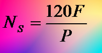
Synchronous speed refers to the rotational speed at which the magnetic field in the stator of an AC motor rotates. This speed is determined by the frequency of the power supply and the number of poles in the motor.

Sunday, November 26, 2023

All about Synchronous Motor

Synchronous Motor

Synchronous motors are a type of AC (alternating current) electric motor where the rotation of the shaft is synchronized with the frequency of the supply current. 

What is a  Synchronous Motor and How Differ from other motors?

A synchronous motor operates based on the principle of synchronism between the rotating magnetic field produced by the stator and the rotor's magnetic field.

Sunday, November 5, 2023

Motor Principle and DC Motor Construction

The motor principle, often referred to as the motor principle of operation, is a fundamental concept in physics and engineering that explains how electric motors work. It's based on the interaction between magnetic fields and electrical currents, and it forms the basis for the operation of various types of electric motors, such as DC (direct current) motors and AC (alternating current) motors. To define the motor principle, you can describe it as follows:

What is the DC Working Motor Principle?
Principle of Motor
Fig-1: Motor Principle

Saturday, October 21, 2023

ESSENTIAL FORMULAS FOR MOTOR ENGINEERING

Essential Formulas for Motor Engineering

Motor Engineering is a vital part of the Engineering sector. There is no industry where a motor is not used; from utility to machinery keeping it running is mandatory. 

Due to the use of huge motors, a large portion of everyday work time also consumed this fellow; and need to face new and critical problems every time.

Yes, friends, to solve problems sometimes a quick and short-cut formula is very effective. That is the main reason today's presentation is on a very easy and basic formula related to motors which we call an Essential Formula for Motor engineering.

We know, You who are engaged with motor engineering know these formulas very well, but sometimes memory is lost. Hope this will help like a friend.

Ohm's Law Easy Use

Thursday, February 16, 2023

Three Phase Motor Connection Diagram


3-phase motor wiring diagram

Three Phase Motor Connection Schematic, Power, and Control Wiring Installation Diagrams. Star-Delta (Y-Δ) 3-phase Motor Starting Methods.

Three-Phase Motor Connection Diagram and Wiring Procedure · Find out the terminals of each winding of the motor.


We will show you the three-phase motor terminal connection or wiring procedure for- 

  •  3-phase motor wiring diagram 6 wire
  •  3-phase motor wiring diagram 9 wire
  •  3-phase motor wiring diagram 12 wire


3-phase star delta motor connection diagram

This article not showing you the 3-phase star delta motor connection diagram. If you are interested to know the three-phase star delta starter motor connection schematic diagram then you can visit the full document in another article on-

Thursday, December 29, 2022

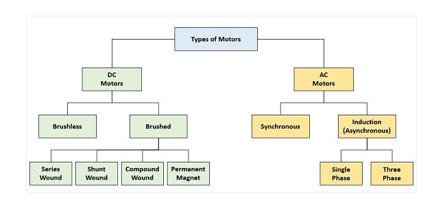
AC and DC Motors Types


Common Types of AC and DC Motors
Motor Types Block Diagram

Common Types of AC and DC Motors

An AC motor can be defined as an electric motor that is driven by an alternating current (AC). A DC motor is also a rotatory electric motor that converts Direct current (DC energy) into mechanical energy. 


An electrical motor is mainly classified into three types.
  1. AC Motors.
  2. DC Motors.
  3. Special Motors.

Farther it can be divided into 4 types as follow:
AC motors are mainly of two types – synchronous AC motors and induction motors.

  1. Synchronous
  2. Asynchronous(Induction)
  3. Brushed
  4. Brushless

DC Motor may be divided into the following 4 ways

  1. Permanent Magnet DC Motors. The permanent magnet motor uses a permanent magnet to create field flux. 
  2. Series DC Motors. In a series DC motor, the field is wound with a few turns of a large wire carrying the full armature current. ...
  3. Shunt DC Motors.
  4. Compound DC Motors.

What is Electric Motor?

ANS. An electric motor is an electrochemical device that converts electrical energy into mechanical energy. Most electric motors operate through the interaction of a magnetic field and current-carrying conductors to generate force.

Two essential parts of a motor

An electric motor consists of two major parts, 
rotor and stator.


 Advantages and Disadvantages of AC and DC Motors

Advantages of AC Motors:

  1. Low cost,
  2. long life,
  3. high efficiency,
  4. large ratings available (to 1 MW or more),
  5. a large number of standardized types.

Disadvantages of AC Motors:

  1. Starting inrush current can be high,
  2. speed control requires a variable frequency source.

Advantages of DC Motors:

  1. Precision positioning,
  2. High holding torque,
  3. Long lifespan,
  4. Low maintenance,
  5. High efficiency.

Disadvantages of DC Motors:

  1. Some can be costly,
  2. Require a controller,
  3. Higher initial cost,
  4. Requires a controller.

Wednesday, September 7, 2022

How does an Induction Motor work ?


How does an Induction Motor work 

The AC induction motor is well suited to applications requiring constant speed operation. In general, the induction motor is cheaper and easier to maintain compared to other alternatives.

The induction motor is made up of the stator, stationary windings, and rotor. The stator consists of a series of wire windings of very low resistance permanently attached to the motor frame. As a voltage and a current are applied to the stator winding terminals, a magnetic field is developed in the windings. By the way, the stator windings are arranged, and the magnetic field appears to synchronously rotate electrically around the inside of the motor housing.

The rotor is comprised of a number of thin bars, usually aluminum, mounted in a laminated cylinder. The bars are arranged horizontally and almost parallel to the rotor shaft. At the ends of the rotor, the bars are connected together with a “shorting ring.” The rotor and stator are separated by an air gap which allows free rotation of the rotor.


Induction Motor:

The induction motor is very much important for the industrial revolution. Every electrical engineer and electrical crew related to the work field of Induction motors should have a clear conception. 

This video clip of "How does Induction Motor work" will be quick and helpful.

Single-phase induction motors are used extensively for smaller loads, such as household appliances like fans. Although traditionally used in fixed-speed service, induction motors are increasingly being used with variable-frequency drives (VFDs) in variable-speed service.

A three-phase Induction Motor is Self Starting. When the supply is connected to the stator of a three-phase induction motor, a rotating magnetic field is produced, the rotor starts rotating and the induction motor starts. At the time of starting, the motor slip is unity, and the starting current is very large.

As the motor accelerates the slip reduces and the voltage induced in the rotor also get reduced. To limit this starting current the starter is used to start the induction motor. Reducing the stator voltage- Star-delta starter. Adding external resistance to the rotor circuit- For slip ring motor.

Thursday, March 31, 2022

Star Delta Starter Line Diagram and Its Working Principle

Fig: Three Phase Motor connection diagram with a star-delta starter.

What is Star Delta Starter for Motor Starting?


Star-Delta starter is an electrical motor starting device, generally uses in big size motors to overcome some technical limitations. Star and Delta mean here 2 separate states of motor running, first Star connection and then Delta connection.

The starting current of any heavy electric motor can be more than 4 times the normal load current it draws when it has gained speed and has reached its normal running condition. 

To overcome this initial high current enchanting problem, such arrangement needs Star connection at starting time and if Star connection has sufficient torque to run up to 75% to %80 of full load speed, then the motor can be connected in Delta mode.

When the motor is connected to the Delta configuration the phase voltage increases by 173% and phase currents increase by the same ratio. The line current increases three times its value in star connection.

What Problem Starting Motor without Star-Delta?

We already know, if the motor starts simply when connected in Delta, the starting current would be huge just to be able to start the motor, not to running condition. To do this would require -

Sponsored:
v Large capacity circuit breakers to allow the start-up surge current to pass without immediately shutting the motor off.
v Oversized 3-phase power service cables require just for starting time, but the normal running time is not necessary.
v Large size of coils and contacts on the relays or contractors need to control the motor, but normal running time needs smaller sizes of them.

Sometimes, utility company also do not permits the big motor to start without a Star-Delta starter because of system instability due to switching transients. 

How Wiring a Star-Delta Starter for Motor?

Following the figure below, the power connection between magnetic contact for Main, Star, Delta and motor is shown in the schematic line diagram and wiring diagram for easy wiring.
Star-Delta Starter Connection
Star-Delta Starter Connection with Control wiring

What is Important During Star-Delta Transition Period?


It is important that the break between the Star contractor switch OFF and the Delta contactor switch is ON because the Star contactor must be reliably quenched before the Delta contactor is activated. During the transition period of switch-over, the motor must be free running with little deceleration. It is also important that the switch over pause is not too long, it may generate a voltage of its own and this may add to or subtract from the applied line voltage.

That’s all for the Star-Delta starter for today; here in this article, we discussed only motor starting by 3 magnetic contracts Star-Delta, solid-state motor starters from different companies also are available in the market now.

Sunday, October 4, 2020

LOW VOLTAGE CONTROLED MOTOR WIRING SYSTEM

Three Phase Motor Wiring
Fig- Low Voltage Motor Control Wiring Diagram

Three Phase & Single Phase Motor Starter Wiring System with Low Voltage Control


This article for the purpose to present the wiring system for both single and three-phase magnetic controlled motor with low voltage control (LVC) system.  Who think safety is the first priority for motor starter wiring, this article will help them. Motor ON-OFF switch is controlled herewith safe low voltage instate of the supplied power line.

The main and special feature in this motor control system is no voltage or low voltage protection system, low voltage control system, motor overload protection system refer to the figure below.

Main Safety Feature for LVC Motor Starter

Due to low voltage or no voltage, the magnetic contact will release the contact and motor will disconnect from the power. When power reinstates, if the motor restart automatically that may because of the dangerous accident for motor or human. To prevent this auto-restart a manual Start & Stop system is included here in this system. If temporary power failure then until the manual start, the motor will remain stopped.

The main supply voltage is dangerous for an electrical shock during coming very near to ON-OFF switch. But in low voltage controlling system what is provided here can eliminate the dangerous electric shock provability. Here ON-OFF system operates by the 24-volt low voltage that is very much safe for the operator.

If motor being overloaded and run for a long time then hues possibilities to burnout the equipment. Prevent motor damage from overload a motor overload protection system is also associated with this low voltage motor control system, a thermal overload relay which protects the motor from overloaded.

Every electrical installing and servicing should not try except clear understanding and qualified electrical personnel.

Three Phase LVC Motor Starter Wiring Diagram

Sponsored:


Refer to the above 3 phase LVC motor starter wiring diagram, if you study the wiring line and try to find the basic components of the diagram, you will find the following major components:
      • magnetic contactor with coil;
      • overload with heater;
      • start/stop station;
      • connection and relation between different component.

The unique feature of this wiring diagram shows the relation and connection of both power circuit and control circuit together which makes very easy understanding even for any new technician. The blue line shows the power line and the red line shows the control wiring. Also, all component are shown in black colour and grounding or earthing system shown in the yellow-green line.

Single Phase LVC Motor Starter Wiring Diagram
Actually, nothing special for single-phase LVC motor starter if you have the three-phase wiring diagram, just consider the phase number 3 is not in the above 3 phase diagram, then you will get a single phase wiring diagram. Single-phase motor terminal T1 & T2 and power source L1 & L2 will remain in the above diagram.

Hope you enjoyed, if you think it is helpful for others then share for them, or if you have a better idea write a comment in share space below.

Saturday, February 15, 2020

What is Difference Between Dynamo and Generator ?

DC & AC Generator
Fig: Basic idea of DC & AC generator

What is Difference Between Dynamo and Generator?


Dynamo- One of the simplest and earliest electrical generators, used to generate electrical power for industry. Dynamos were quickly replaced by other electrical generators because of the advantages of Alternating Current (AC).

The question is actually a bit confusing because the generator can be divided into two: one is DC generator and the other is AC generator or Alternator.

So if you mean alternator by generator then maybe the difference can be made that dynamo produces DC current and Alternator produces AC current.

And if the dynamo means DC and the generator means the alternator-dynamo together, then…

Dynamo is the kind of system that can only produce DC current. The generator AC current can be converted to DC via a commutator.


The dynamo is actually the old state of the generator of the era. Alternator generators are now used throughout the world. Although there are times where low power DC flow is required where dynamo is still used.

Today Dynamo means DC (Direct Current) generator and Generator means alternator or AC generator. Further details a DC generator generates AC current, but it contains a simple device called commutator to convert AC into DC. A commutator diverts the flow of electrons inside the DC generator, so that the energy that appears at the output is a pulsing direct flow. On the other hand AC generator does not need a commutator and it generates AC directly. Dynamos and Generators both convert mechanical rotation like wind, hydro, gas, waves ect. into electrical power.


Thomas Edison believed that the base of future electricity would be DC, but Nikola Tesla believed on AC. Finally Nikola Tesla proofed he is correct.


Early people used to battery for electricity, but batteries were not reliable and cost effective. However the Dynamo rapidly changed as a profitable and reliable technology in electricity.

Dynamo or Generator is made up of Stator or stationary magnets which create a powerful magnetic field, and a Rotor or rotating magnet which distorted and cuts through the magnetic lines of flux of the stator. When the rotor cuts through lines of magnetic flux it makes electricity.


Short History of Dynamos and Generators

In 1820 Michael Faraday and Joseph Henry first discovered and prepared some documents on electromagnetic induction. Faraday Disk is the first electric generator which shows that rotary mechanical power can be converted into electric power. Electric power generation race is started from here, latter on this lead to experimentation in Europe and America about Dynamos/Generators.
1832, Hippolyte Pixii & Ampère built the first hand cranked dynamo using a commutator. Latter on 1860 Antonio Pacinotti created a dynamo that provided continuous DC power. H Wilde made the commercially successful Alliance generator in 1866 for powering arc lamps in lighthouses. All of these generators employed permanent magnets.

Instead of weak permanent magnet dynamo/generator, more powerful self powered electromagnet in stator brought by Werner Von Siemens and Charles Wheatstone in 1867. Commercial revolution of electricity generation is happened by Zenobe Gramme in1871; he used an iron core to give improved and efficient path for magnetic flux which increased the power of the dynamo/generator and make wide usable for many commercial applications.


The best system for power generation, 3-phase AC generator developed during 1886 to 1891, many scientist /engineer from USA, Germany, Russia and Italy worked to improve generator.


What is the Characteristics of DC Generator?

Tuesday, November 6, 2018

Motor and Pump Application Formula Save Energy and Make You Smart Designer


How Motor and Pump Application Formula can Save Energy and Make You Smart Designer?

Motor and Pump applications simple formula can save energy by helping effective design for using maximum efficiency of your equipment. 


Some times we ignore these basic design formula and use larger size of equipment using thump-role formula which cases extra money energy as wastage. 
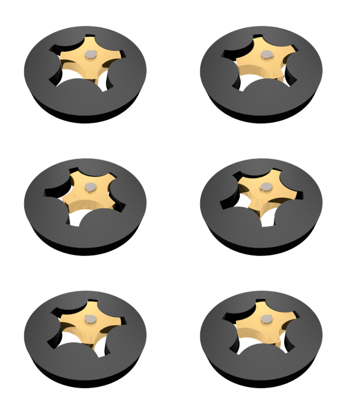


A gerotor
A gerotor (image does not show intake or exhaust) (Photo credit: Wikipedia)
If we love ourself to be a energy saver or go to as green environment; we should take care of every bit of energy uses. Following motor and pump applications formula can help us to effective use of energy.

Centrifugal Applications


AFFINITY LAWS

The Affinity Laws of centrifugal pumps or fans indicates the influence on volume capacity, head (pressure) and/or power consumption of a pump or fan due to


  • change in speed of wheel - revolutions per minute (rpm)
  • geometrically similarity - change in impeller diameter
Following three affinity formulas are related with simply motor horse powerRPM (revolution per minute), Flow and pressure.

Flow2
=
RPM2
Flow1
RPM1
Pres2
=
(RPM2)2
Pres1
(RPM1)2
HP2
=
(RPM2)3
HP1
(RPM1)3


Where:
Pres=Pressure
RPM= Revolutions Per Minute

FANS AND BLOWERS


Centrifugal Fans and Blowers typically have one of seven types of wheels that draw the air into the inlet of the blower housing, through the wheel, and discharges it at 90 degrees out through the discharge of the housing.

The two most common types of Centrifugal Blowers are Pressure Blowers and Volume Blowers.

Fans and Blowers are very common uses in industry, Basic three formula can help you to design effective and perfect size of fan and blower as your desired. 

HP  =
CFM x PSF
33000 x Efficiency of Fan
HP  =
CFM x PIW
6356 x Efficiency of Fan


HP  =
CFM x PSI
229 x Efficiency of Fan


Where:
CFM= Cubic Feet per Minute
PIW= Inches of Water Gauge
PSF= Pound per Square Foot
PSI= Pound per Square Inches

PUMPS

Pump is a device that moves fluids (liquids or gases), or sometimes slurries, by mechanical action. Pumps can be classified into three major groups according to the method they use to move the fluid: direct lift, displacement, and gravity pumps.

Perfect capacity of pump design and operation is very important which can help the following two simple formula.


HP  =
GPM x FT x Specific Gravity
3960 x Efficiency of Pump


HP  =
GPM x PSI x Specific Gravity
1713 x Efficiency of Pump


Where:
FT= Head in Feet
GPM= Gallons Per Minute
PSI= Pounds Per Square Inch

VOLUME OF LIQUID IN A TANK


Gallons= 5.875 x D2 x H
1 gallon (US) of water weights 8.33 lb
Specific gravity of water- 1.0

Where:
D= Diameter of Tank in feet
H= Height of liquid in feet

Motor Application Formulas

Following motor applications formula is necessary everyday every moment.  It will help to calculate your motor's HP (Horse Power), Kilowatts, Torque in Pound-feet or Newton-meter.

HP(Horse Power)  =
Torque (lb-ft) x RPM
5252


Kilowatts  =
Torque (N-m) x RPM
9550


Torque (lb-ft)  =
Horse Power (HP) x 5252
RPM


Torque (N-m) =
Kilowatts x 9550
RPM


1HP= 746 watts
Hope motor and pump application formula will help to design a smart and effective energy saving initiative. 

You may like the following pages