WO2015156120A1 - 光学素子 - Google Patents
光学素子 Download PDFInfo
- Publication number
- WO2015156120A1 WO2015156120A1 PCT/JP2015/058919 JP2015058919W WO2015156120A1 WO 2015156120 A1 WO2015156120 A1 WO 2015156120A1 JP 2015058919 W JP2015058919 W JP 2015058919W WO 2015156120 A1 WO2015156120 A1 WO 2015156120A1
- Authority
- WO
- WIPO (PCT)
- Prior art keywords
- microlens
- axis
- plane
- optical element
- curved surface
- Prior art date
Links
Images
Classifications
-
- F—MECHANICAL ENGINEERING; LIGHTING; HEATING; WEAPONS; BLASTING
- F21—LIGHTING
- F21V—FUNCTIONAL FEATURES OR DETAILS OF LIGHTING DEVICES OR SYSTEMS THEREOF; STRUCTURAL COMBINATIONS OF LIGHTING DEVICES WITH OTHER ARTICLES, NOT OTHERWISE PROVIDED FOR
- F21V5/00—Refractors for light sources
- F21V5/002—Refractors for light sources using microoptical elements for redirecting or diffusing light
- F21V5/004—Refractors for light sources using microoptical elements for redirecting or diffusing light using microlenses
-
- F—MECHANICAL ENGINEERING; LIGHTING; HEATING; WEAPONS; BLASTING
- F21—LIGHTING
- F21V—FUNCTIONAL FEATURES OR DETAILS OF LIGHTING DEVICES OR SYSTEMS THEREOF; STRUCTURAL COMBINATIONS OF LIGHTING DEVICES WITH OTHER ARTICLES, NOT OTHERWISE PROVIDED FOR
- F21V5/00—Refractors for light sources
- F21V5/008—Combination of two or more successive refractors along an optical axis
-
- F—MECHANICAL ENGINEERING; LIGHTING; HEATING; WEAPONS; BLASTING
- F21—LIGHTING
- F21V—FUNCTIONAL FEATURES OR DETAILS OF LIGHTING DEVICES OR SYSTEMS THEREOF; STRUCTURAL COMBINATIONS OF LIGHTING DEVICES WITH OTHER ARTICLES, NOT OTHERWISE PROVIDED FOR
- F21V5/00—Refractors for light sources
- F21V5/04—Refractors for light sources of lens shape
-
- G—PHYSICS
- G02—OPTICS
- G02B—OPTICAL ELEMENTS, SYSTEMS OR APPARATUS
- G02B27/00—Optical systems or apparatus not provided for by any of the groups G02B1/00 - G02B26/00, G02B30/00
- G02B27/09—Beam shaping, e.g. changing the cross-sectional area, not otherwise provided for
- G02B27/0938—Using specific optical elements
- G02B27/095—Refractive optical elements
- G02B27/0955—Lenses
- G02B27/0961—Lens arrays
-
- G—PHYSICS
- G02—OPTICS
- G02B—OPTICAL ELEMENTS, SYSTEMS OR APPARATUS
- G02B27/00—Optical systems or apparatus not provided for by any of the groups G02B1/00 - G02B26/00, G02B30/00
- G02B27/30—Collimators
-
- G—PHYSICS
- G02—OPTICS
- G02B—OPTICAL ELEMENTS, SYSTEMS OR APPARATUS
- G02B3/00—Simple or compound lenses
- G02B3/0006—Arrays
-
- G—PHYSICS
- G02—OPTICS
- G02B—OPTICAL ELEMENTS, SYSTEMS OR APPARATUS
- G02B3/00—Simple or compound lenses
- G02B3/0006—Arrays
- G02B3/0037—Arrays characterized by the distribution or form of lenses
- G02B3/0056—Arrays characterized by the distribution or form of lenses arranged along two different directions in a plane, e.g. honeycomb arrangement of lenses
-
- G—PHYSICS
- G02—OPTICS
- G02B—OPTICAL ELEMENTS, SYSTEMS OR APPARATUS
- G02B5/00—Optical elements other than lenses
- G02B5/02—Diffusing elements; Afocal elements
- G02B5/0205—Diffusing elements; Afocal elements characterised by the diffusing properties
- G02B5/021—Diffusing elements; Afocal elements characterised by the diffusing properties the diffusion taking place at the element's surface, e.g. by means of surface roughening or microprismatic structures
- G02B5/0215—Diffusing elements; Afocal elements characterised by the diffusing properties the diffusion taking place at the element's surface, e.g. by means of surface roughening or microprismatic structures the surface having a regular structure
-
- G—PHYSICS
- G02—OPTICS
- G02B—OPTICAL ELEMENTS, SYSTEMS OR APPARATUS
- G02B5/00—Optical elements other than lenses
- G02B5/02—Diffusing elements; Afocal elements
- G02B5/0205—Diffusing elements; Afocal elements characterised by the diffusing properties
- G02B5/021—Diffusing elements; Afocal elements characterised by the diffusing properties the diffusion taking place at the element's surface, e.g. by means of surface roughening or microprismatic structures
- G02B5/0231—Diffusing elements; Afocal elements characterised by the diffusing properties the diffusion taking place at the element's surface, e.g. by means of surface roughening or microprismatic structures the surface having microprismatic or micropyramidal shape
Definitions
- the present invention relates to an optical element that forms a light image having a uniform illuminance distribution.
- Optical elements that convert the distribution of light from a light source have been developed to form an optical image used for alignment marks and visual displays for measuring instruments, medical instruments, industrial robots, and the like.
- optical elements there are an optical element that combines divided cylindrical lenses (for example, Patent Document 1) and an optical element that has a polygonal pyramid shape with extended side surfaces (for example, Patent Document 2).
- An optical element includes a plurality of microlenses.
- Each microlens is delimited by N sides of the convex polygon, a microlens vertex away from the plane of the convex polygon, and a line connecting the microlens vertex and the N vertices of the convex polygon.
- a straight line passing through the microlens vertex and orthogonal to the plane is defined as the z-axis, the intersection of the z-axis and the plane is defined as the origin, the origin in the plane is defined, and a certain side
- the curved surface of the microlens of the optical element of this embodiment has a uniform illuminance distribution of a light image formed on a plane perpendicular to the parallel light flux by a uniform parallel light flux that is perpendicularly incident on the polygonal plane of the microlens.
- the difference between the inclination of the virtual curved surface F (x) and x with respect to x is 0.035 or less at 0.25 ⁇ t ⁇
- the illuminance distribution of the light image formed by the entire microlens array is substantially uniform. Since the area of the curved surface of 0.25 ⁇ t ⁇
- the optical element according to the first embodiment of the present invention in a cross section including the z axis and parallel to the x axis, a direction in which a light ray that enters the plane perpendicularly and travels in the z axis direction exits from the virtual curved surface.
- the z-axis is ⁇
- z F (x) as
- the convex polygon is a regular polygon.
- the z axis passes through the center of the regular polygon.
- N is 3, 4 or 6.
- the optical element according to the sixth embodiment of the present invention is configured so that the shapes of curved surfaces corresponding to adjacent sides are different.
- the shape of the curved surface corresponding to the adjacent sides of the square is different, it is a cross-shaped optical image with different lengths in the respective directions of the two adjacent sides of the square, and an optical image with a substantially uniform illuminance distribution Can be formed.
- the optical element according to the sixth embodiment of the present invention is formed integrally with a collimator lens.
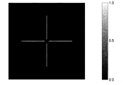
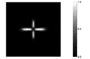
- FIG. 1 shows the illumination intensity distribution of the optical image by the micro lens array of Example 1 in the plane arrange
- FIG. 4 is a diagram showing the inclination of the curved surface of the microlens of Example 1. It is a figure which shows the illumination intensity distribution of the optical image by the microlens array of a comparative example in the plane arrange
- FIG. 6 is a diagram illustrating a microlens array of Example 3.
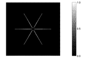
- FIG. 6 It is a figure which shows the illumination intensity distribution of the optical image by the microlens array of Example 3 in the plane arrange
- FIG. 6 is a diagram showing the inclination of the curved surface of the microlens of Example 3. 6 is a diagram illustrating an optical system of Example 4. FIG. FIG. 6 is a diagram showing the shape of an optical element of Example 4.
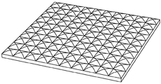
- FIG. 1 is a diagram showing a microlens array which is an optical element according to an embodiment of the present invention.
- the microlens array includes a plurality of microlenses having the same shape and arranged in a plane.
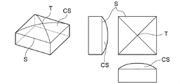
- FIG. 2 is a diagram showing a microlens that is a component of the microlens array of FIG.
- the microlens includes four sides S of a square, a microlens vertex T, and four curved surfaces CS separated by a curve connecting the four vertices of the square and the microlens vertex T.
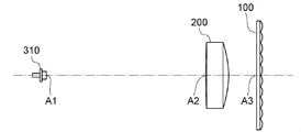
- FIG. 3 is a diagram illustrating an optical system including the light source 310, the collimator lens 200, and the microlens array 100.
- the optical axis of the optical system is indicated by a one-dot chain line.
- the optical axis passes through the center point A1 of the light emitting surface of the light source 310, coincides with the principal axis of the collimator lens 200, and is determined to be orthogonal to the light source side surface of the microlens array 100.
- the light emitted from the light source 310 is converted into a light beam parallel to the optical axis by the collimator lens 200 and is incident on the light source side surface of the microlens array 100 perpendicularly.
- the parallel light beam incident on the microlens array 100 is emitted in a predetermined direction by the microlens.
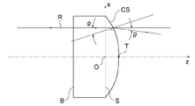
- FIG. 4 is a first diagram for explaining the function of the microlens.
- the bottom surface B of the microlens is parallel to the four sides S of the square.
- a straight line orthogonal to the bottom surface B and passing through the microlens apex T is taken as the z-axis.
- An intersection point between the z-axis and the square surface is defined as an origin O, and a straight line passing through the origin O, parallel to two sides of the square and orthogonal to the other two sides in the square surface is defined as an x-axis.
- FIG. 4 shows a cross section of the microlens including the z-axis and the x-axis.
- the z coordinate of the curved surface CS including the side of the square perpendicular to the x axis is determined to be a function of only the x coordinate. That is, the curved surface CS can be expressed by the following equation.
- a light ray R incident perpendicularly to the bottom surface B of the microlens enters the curved surface CS of the microlens at an incident angle ⁇ and is emitted toward the angle ⁇ with respect to the z axis. That is, the angle ⁇ is an acute angle between the direction in which the light emitted from the curved surface CS travels and the z axis.
- the angle ⁇ and the incident angle ⁇ an angle measured clockwise with respect to the z-axis is positive, and an angle measured counterclockwise is negative.
- the parallel luminous flux incident perpendicularly to the bottom surface B becomes a luminous flux having a spread only in the zx direction after passing through the curved surface CS including the side perpendicular to the x-axis. Therefore, an optical image formed on the plane perpendicular to the z-axis by the luminous flux becomes a linear shape having a predetermined length in the x-axis direction.
- an optical image formed on a plane perpendicular to the z-axis by a light beam incident perpendicularly to the bottom surface B and passing through the curved surface CS including a side parallel to the x-axis is an x-axis direction. It is a line having a predetermined length in the vertical direction. Therefore, the optical image formed on the plane perpendicular to the z-axis is a line having a predetermined length in the x-axis direction and the direction perpendicular to the x-axis direction.
- FIG. 5 is a second diagram for explaining the function of the microlens.
- the diagram on the right side of FIG. 5 shows a cross section of the microlens including the z-axis and the x-axis.
- the left side of FIG. 5 is a plan view of the microlens.
- Two light rays perpendicularly incident on the bottom surface B of the microlens are denoted by R1 and R2.
- x-coordinate of the ray R1 is x 1
- x-coordinate of the ray R2 is x 2.
- x 1 ⁇ x 2 .
- ray R1 After ray R1 is passing through the curved surface CS, and travels in a direction which forms a z-axis and the angle theta 1, ray R2 after passing through a curved surface CS, travels in a direction which forms a z-axis and an angle theta 2.
- C is a positive constant.
- the microlens having a cross-sectional shape satisfying the expressions (8a) and (8b) makes the irradiance uniform on a plane that is sufficiently separated from the z axis.
- Expressions (8a) and (8b) can be expressed by the following expressions.
- the contribution to the irradiance distribution is substantially proportional to the area of the optical surface, even if the expression (10) is not satisfied in a part of the area near the optical axis, the influence on the entire irradiance distribution is small. , Its function is not impaired. For example, the area of 25% of the distance t from the optical axis is about 6%, and even if the area deviates from the expression (10) within this range, if the other range satisfies the expression (10), the radiation pattern is almost uniform. The irradiance distribution can be obtained.
- the optical system of Example 1-2 and the comparative example is composed of the optical system shown in FIG.
- the specifications of the light source 310 and the collimator lens 200 in Example 1-2 and the comparative example are the same, and the specifications of the collimator lens 200 are as follows.
- the thickness of the collimator lens 200 means the center thickness along the optical axis.
- the position of the microlens array 100 is the intersection of the surface of the microlens array 100 that is not provided with a lens, that is, the bottom surface, and the optical axis. It is the position of A3 in FIG.
- the thickness of the microlens array 100 means the distance from the bottom surface of the microlens to the apex of the microlens, that is, the distance from B to T in FIG.
- Microlens of Example 1 The curved surface of the microlens of Example 1 can be expressed by the following equation.
- Table 1 is a table showing coefficients of the equation (11) indicating the curved surface of the microlens of Example 1.
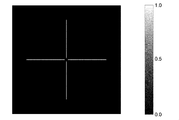
- FIG. 6 is a diagram illustrating the illuminance distribution of a light image by the microlens array of Example 1 on a plane arranged perpendicular to the optical axis at a position 3.0 meters in the optical axis direction from the center point A1 of the light source. .
- the optical axis is arranged in the horizontal direction.
- Two sides of the square of the microlens are arranged in the horizontal direction, and the other two sides are arranged in the vertical direction. Therefore, as shown in FIG. 6, a light image having a linear irradiance distribution having a predetermined length appears in the horizontal direction and the vertical direction.
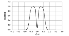
- FIG. 7 shows the illuminance distribution in the horizontal direction of the optical image by the microlens array of Example 1 on a plane arranged perpendicular to the optical axis at a position 3.0 meters from the center point A1 of the light source in the optical axis direction.
- FIG. The horizontal axis in FIG. 7 indicates the horizontal position on the plane.
- the position where the optical axis and the plane intersect is the position of 0.0 on the horizontal axis.
- the vertical axis in FIG. 7 indicates relative illuminance.
- the relative illuminance 1 is the maximum value of illuminance.
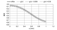
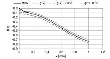
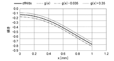
- FIG. 8 is a diagram illustrating the inclination of the curved surface of the microlens according to the first embodiment.
- the horizontal axis in FIG. 8 represents the x-axis coordinate of the microlens
- the vertical axis in FIG. 8 represents the slope of the curved surface of the microlens of Example 1.
- the inclination of the curved surface of the microlens of Example 1 satisfies the formula (10) in the entire range of x.
- the curved surface of the microlens of the comparative example has an arc shape with a center curvature radius of 1.66 mm.
- FIG. 9 is a diagram showing an illuminance distribution of a light image by a microlens array of a comparative example on a plane arranged perpendicular to the optical axis at a position 3.0 meters in the optical axis direction from the center point A1 of the light source.
- the optical axis is arranged in the horizontal direction.
- Two sides of the square of the microlens are arranged in the horizontal direction, and the other two sides are arranged in the vertical direction. Therefore, as shown in FIG. 9, a light image having a linear irradiance distribution having a predetermined length appears in the horizontal direction and the vertical direction.
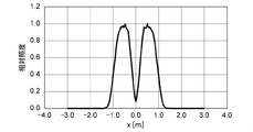
- FIG. 10 is a diagram showing the illuminance distribution in the horizontal direction of the optical image by the microlens array of the comparative example on a plane arranged perpendicular to the optical axis at a position 3.0 meters from the center point A1 of the light source in the optical axis direction. It is.
- the horizontal axis in FIG. 10 indicates the horizontal position on the plane.
- the position where the optical axis and the plane intersect is the position of 0.0 on the horizontal axis.
- the vertical axis in FIG. 10 indicates relative illuminance.
- the relative illuminance 1 is the maximum value of illuminance.
- FIG. 11 is a diagram illustrating the inclination of the curved surface of the microlens of the comparative example.
- the horizontal axis in FIG. 11 indicates the x-axis coordinate of the microlens
- the vertical axis in FIG. 11 indicates the slope of the curved surface of the microlens of the comparative example.
- the inclination of the curved surface of the microlens of the comparative example does not satisfy Expression (10) in a range of 70% or more of the entire range of x.
- Microlens of Example 2 The curved surface of the microlens of Example 2 can be expressed by the following equation.
- Table 2 is a table showing the coefficients of Expression (11) indicating the curved surface of the microlens of Example 2.
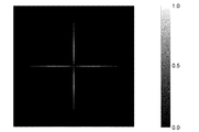
- FIG. 12 is a diagram showing the illuminance distribution of a light image by the microlens array of Example 2 on a plane arranged perpendicular to the optical axis at a position 3.0 meters from the center point A1 of the light source in the optical axis direction. .
- the optical axis is arranged in the horizontal direction.
- Two sides of the square of the microlens are arranged in the horizontal direction, and the other two sides are arranged in the vertical direction. Therefore, as shown in FIG. 12, a light image having a linear irradiance distribution having a predetermined length appears in the horizontal direction and the vertical direction.
- FIG. 13 shows the illuminance distribution in the horizontal direction of the optical image by the microlens array of Example 2 on a plane arranged perpendicular to the optical axis at a position 3.0 meters from the center point A1 of the light source in the optical axis direction.
- FIG. The horizontal axis in FIG. 13 indicates the horizontal position on the plane.
- the position where the optical axis and the plane intersect is the position of 0.0 on the horizontal axis.
- shaft of FIG. 13 shows relative illumination intensity.
- the relative illuminance 1 is the maximum value of illuminance.
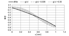
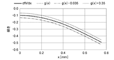
- FIG. 14 is a diagram illustrating the inclination of the curved surface of the microlens according to the second embodiment.
- the horizontal axis in FIG. 14 represents the x-axis coordinate of the microlens
- the vertical axis in FIG. 14 represents the slope of the curved surface of the microlens in Example 2.
- slope of virtual curved surface with uniform illumination distribution Indicates.
- the inclination of the curved surface of the microlens of Example 2 satisfies the formula (10) in a range excluding x ⁇ 0.1.
- the optical system of Example 3 and the optical system of microlens Example 3 are the optical systems shown in FIG.
- the thickness of the collimator lens 200 means the center thickness along the optical axis.
- FIG. 15 is a view showing a microlens array of Example 3.
- the position of the microlens array 100 is the surface of the microlens array 100 that does not include the lens, that is, the intersection of the bottom surface and the optical axis, that is, the position of A3 in FIG.
- the thickness of the microlens array 100 means the distance from the bottom surface of the microlens to the apex of the microlens, that is, the distance from B to T in FIG.
- the curved surface of the microlens of Example 3 can be expressed by the following formula.
- Table 3 is a table showing the coefficients of the expression (11) indicating the curved surface of the microlens of Example 3.
- FIG. 16 is a diagram illustrating the illuminance distribution of a light image by the microlens array of Example 3 on a plane arranged perpendicular to the optical axis at a position 3.0 meters in the optical axis direction from the center point A1 of the light source. .
- the optical axis is arranged in the horizontal direction.
- Two sides of the regular hexagon of the microlens are arranged in the vertical direction. Therefore, as shown in FIG. 16, six light images having a linear irradiance distribution appear.
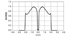
- FIG. 17 shows the illuminance distribution in the horizontal direction of the optical image by the microlens array of Example 3 on a plane arranged perpendicular to the optical axis at a position 3.0 meters from the center point A1 of the light source in the optical axis direction.
- FIG. The horizontal axis in FIG. 17 indicates the horizontal position on the plane.
- the position where the optical axis and the plane intersect is the position of 0.0 on the horizontal axis.
- the vertical axis in FIG. 17 indicates relative illuminance.
- the relative illuminance 1 is the maximum value of illuminance.
- FIG. 18 is a diagram illustrating the inclination of the curved surface of the microlens according to the third embodiment.
- the horizontal axis in FIG. 18 represents the x-axis coordinate of the microlens
- the vertical axis in FIG. 18 represents the slope of the curved surface of the microlens of Example 3.
- the inclination of the curved surface of the microlens of Example 3 satisfies Expression (10) in the entire range of x. However, in the range of 0.5 ⁇ x ⁇ 0.8, it is almost equal to the upper limit of Expression (10).
- FIG. 19 is a diagram showing an optical system of Example 4.
- the optical system according to the fourth embodiment includes a light source 320, a collimator lens 1200, and a micro lens array 1100.
- the collimator lens 1200 and the micro lens array 1100 are integrally formed.
- the collimator lens 1200 includes a transmission surface 1201 and a reflection surface 1203. The light emitted from the light source 320 and transmitted through the transmission surface 1201 and the light reflected by the reflection surface 1203 enter the microlens array 1100 as a parallel light flux.
- the collimator lens 1200 is arranged so that the main axis thereof coincides with the optical axis and the center of the light source 320 passes through the optical axis. In FIG. 19, the optical axis is arranged in the horizontal direction.
- FIG. 20 is a diagram showing the shape of the optical element of Example 4.
- the optical element of Example 4 includes a microlens array 1100 on the exit side of the collimator lens 1200.
- the optical element is arranged so that two adjacent sides of the microlens square are in the horizontal direction and the vertical direction, respectively.
- the transmission surface 1201 of the collimator lens 1200 has an aspheric shape that is convex toward the light source.
- the surface shape is defined by the following equation, where r is the distance from the optical axis.
- z represents the distance in the z-axis direction from the vertex of the transmission surface 1201 located on the optical axis to a point on the surface
- r represents the distance from the optical axis to the point on the surface.
- the position of the transmission surface 1201 of the collimator lens is the intersection of the transmission surface 1201 and the optical axis, that is, the position of B2 in FIG. The position of B2 is the position of the vertex of the transmission surface 1201 described above.
- z 2.25 [mm] means that the distance from the center point B1 to B2 of the light source is 2.25 millimeters.
- the collimator lens reflecting surface 1203 has an even-order aspherical shape convex toward the light source.
- the surface shape is defined as follows, where r is the distance from the optical axis.
- z represents the distance in the z-axis direction from a point z (0) located on the optical axis, which will be described later, to a point on the surface, and r represents the distance from the optical axis to a point on the surface. .
- Parameters defining the reflecting surface 1203 of the collimator lens are as follows.
- the position of the reflecting surface 1203 of the collimator lens is a position on the optical axis corresponding to the value of z (0) in the above formula representing the reflecting surface 1203.
- the thickness of the microlens array 1100 is 2.0 millimeters.
- the curved surface of the microlens of Example 4 can be expressed by the following formula.
- Table 4 is a table showing coefficients of the equation (11) indicating a curved surface (a curved surface including a horizontal side of a square) arranged in the horizontal direction of the microlens of Example 4.
- Table 5 is a table showing coefficients of the equation (11) indicating a curved surface (a curved surface including a square side in the vertical direction) arranged in the vertical direction of the microlens of Example 4.
- FIG. 21 is a diagram illustrating the illuminance distribution of a light image by the microlens array of Example 4 on a plane arranged perpendicular to the optical axis at a position of 3.0 meters in the optical axis direction from the center point B1 of the light source. .
- Two sides of the square of the microlens are arranged in the horizontal direction, and the other two sides are arranged in the vertical direction. Therefore, as shown in FIG. 21, a light image having a linear irradiance distribution having a predetermined length appears in the horizontal direction and the vertical direction.
- FIG. 22 shows the illuminance distribution in the horizontal direction of the optical image by the microlens array of Example 4 on a plane arranged perpendicular to the optical axis at a position 3.0 meters from the central point B1 of the light source in the optical axis direction.
- FIG. The horizontal axis in FIG. 22 indicates the horizontal position on the plane. The position where the optical axis and the plane intersect is the position of 0.0 on the horizontal axis.
- the vertical axis in FIG. 22 represents relative illuminance.
- the relative illuminance 1 is the maximum value of illuminance.
- FIG. 23 shows the illuminance distribution in the vertical direction of the optical image by the microlens array of Example 4 on a plane arranged perpendicular to the optical axis at a position 3.0 meters from the central point B1 of the light source in the optical axis direction.
- FIG. The horizontal axis in FIG. 23 indicates the position in the vertical direction on the plane.
- the position where the optical axis and the plane intersect is the position of 0.0 on the horizontal axis.
- shaft of FIG. 23 shows relative illumination intensity.
- the relative illuminance 1 is the maximum value of illuminance.
- FIG. 24 is a diagram illustrating the inclination of the curved surface in the horizontal direction of the microlens according to the fourth embodiment.
- the horizontal axis in FIG. 24 indicates the x-axis coordinates of the microlens
- the vertical axis in FIG. 24 indicates the slope of the curved surface in the horizontal direction of the microlens in Example 4.
- the inclination of the curved surface in the horizontal direction of the microlens in Example 4 satisfies Expression (10) in the entire range of x.
- FIG. 25 is a diagram illustrating the inclination of the curved surface in the vertical direction of the microlens according to the fourth embodiment.
- the horizontal axis in FIG. 25 represents the x-axis coordinate of the microlens
- the vertical axis in FIG. 25 represents the slope of the curved surface in the horizontal direction of the microlens in Example 4.
- the inclination of the curved surface in the vertical direction of the microlens of Example 4 satisfies Expression (10) in the entire range of x.
- the illuminance distribution of Example 1 is 0.2 ⁇
- the relative illuminance is lower than 0.8 in a range other than 0.3 ⁇
- the illuminance distribution of Example 1 is more uniform than the illuminance distribution of the comparative example.
- the relative illuminance is 0.9 or more in the range of 0.3 ⁇
- the relative illuminance is lower than 0.8 in a range other than 0.3 ⁇
- the illuminance distribution of Example 2 is more uniform than the illuminance distribution of the comparative example.
- the inclination of the curved surface of the microlens of Example 2 does not satisfy Expression (10) in the range of x ⁇ 0.1, but an optical image having a uniform illuminance distribution is realized.
- the relative illuminance is 0.8 or more in the range of 0.2 ⁇
- the relative illuminance in the range is 0.6 or more.
- the relative illuminance is lower than 0.6 in a range other than 0.2 ⁇
- the illuminance distribution of Example 3 is more uniform than the illuminance distribution of the comparative example.
- Equation (10) the slope of the curved surface of the microlens of Example 3 satisfies Equation (10) in the entire range of x, but in the range of 0.5 ⁇ x ⁇ 0.8, Equation (10) Is approximately equal to the upper limit of. If the difference between the inclination of the curved surface of the microlens and the inclination g (x) of the virtual curved surface is larger than in this example, the superiority of the uniformity of the illuminance distribution is impaired.
- Example 22 in the horizontal illuminance distribution of Example 4, the relative illuminance is 0.8 or more in the range of 0.3 ⁇
- the relative illuminance in the illuminance distribution in the vertical direction of Example 4, the relative illuminance is 0.8 or more in the range of 0.3 ⁇
Landscapes
- Physics & Mathematics (AREA)
- General Physics & Mathematics (AREA)
- Optics & Photonics (AREA)
- Engineering & Computer Science (AREA)
- General Engineering & Computer Science (AREA)
- Planar Illumination Modules (AREA)
- Lenses (AREA)
- Projection Apparatus (AREA)
Abstract
Description
z=f(x)
で表し、原点から該辺までの距離をtとして、0≦|x|≦tにおいて
z=F(x)
で表せる仮想曲面を想定し、該マイクロレンズの材料の屈折率をnとし、Aは非負、Cは正の定数として、
z=F(x)
が単調に減少する。
光源310から放出された光は、コリメータレンズ200によって光軸に平行な光束とされ、マイクロレンズアレイ100の光源側の面に垂直に入射される。マイクロレンズアレイ100に入射された平行光束は、マイクロレンズによって所定の方向に向けて射出される。
図4の断面において、マイクロレンズの底面Bに垂直に入射した光線Rは、マイクロレンズの曲面CSに入射角φで入射し、z軸に対して角度θの方向に向けて射出される。すなわち、角度θは曲面CSを射出した光が進む方向とz軸との間の鋭角である。角度θ及び入射角φは、z軸を基準として時計回りに測定した角度を正、反時計回りに測定した角度を負とする。図4から明らかなように、xが正の領域では、角度θは正で入射角φは負あり、xが負の領域では角度θは負で入射角φは正である。底面Bに垂直に入射した平行光束は、x軸に垂直な方向の辺を含む曲面CSを通過した後、zx方向にのみ広がりを持った光束となる。したがって、該光束によって、z軸に垂直な平面上に形成される光像は、x軸方向の所定の長さの線状となる。また、同様に、底面Bに垂直に入射し、x軸に平行な方向の辺を含む曲面CSを通過した光束によって、z軸に垂直な平面上に形成される光像は、x軸方向と垂直な方向の所定の長さの線状となる。したがって、z軸に垂直な平面上に形成される光像は、x軸方向、及びx軸方向と垂直な方向に所定の長さの線状となる。
z=F(x)
で表す。F(x)のx軸に対する傾き角をφとすると、以下の式が成立する。
X≧0のとき
x≧0のとき
x<0のとき
実施例1-2及び比較例の光学系は、図3に示す光学系からなる。実施例1-2及び比較例の光源310及びコリメータレンズ200の仕様は同一であり、コリメータレンズ200の仕様は以下のとおりである。
位置(光源の中心点を基準として):z=30[mm]
材料:BK7(屈折率:n=1.519)
厚み:4.0[mm]
入射面中心曲率半径:130.7[mm]
射出面中心曲率半径:-19.38[mm]
ここで、コリメータレンズ200の位置とは、コリメータレンズ200の入射面と光軸との交点、すなわち図3のA2の位置である。z=30[mm]は、光源の中心点A1からA2までの距離が30ミリメータであることを意味する。コリメータレンズ200の厚みとは、光軸に沿った中心厚を意味する。
位置(光源の中心点を基準として):z=40[mm]
材料:ポリカーボネート(屈折率:n=1.590)
厚み:1.0[mm]
多角形:正方形
正方形のサイズ:一辺が2.0ミリメータの正方形
ここで、マイクロレンズアレイ100の位置とは、マイクロレンズアレイ100のレンズを備えていない面、すなわち底面と光軸との交点、すなわち図3のA3の位置である。z=40[mm]は、光源の中心点A1からA3までの距離が40ミリメータであることを意味する。マイクロレンズアレイ100の厚みとは、マイクロレンズの底面からマイクロレンズの頂点までの距離、すなわち図4のBからTまでの距離を意味する。
比較例のマイクロレンズの曲面は中心曲率半径1.66ミリメータの円弧形状である。
実施例3の光学系は、図3に示す光学系である。実施例3のコリメータレンズ200の仕様は以下のとおりである。
位置(光源の中心点を基準として):z=30[mm]
材料:BK7(屈折率:n=1.519)
厚み:4.0[mm]
入射面中心曲率半径:130.7[mm]
射出面中心曲率半径:-19.38[mm]
ここで、コリメータレンズ200の位置とは、入射面と光軸との交点、すなわち図3のA2の位置である。z=30[mm]は、光源の中心点A1からA2までの距離が30ミリメータであることを意味する。コリメータレンズ200の厚みとは、光軸に沿った中心厚を意味する。
位置(光源の中心点を基準として):z=40[mm]
材料:ポリカーボネート(屈折率:n=1.590)
厚み:1.0[mm]
多角形:正六角形
正六角形のサイズ:対向する辺の間隔(水平方向の長さ)が2.0ミリメータであり、対向する頂点の間隔(鉛直方向の長さ)が2.309ミリメータの正六角形)
ここで、マイクロレンズアレイ100の位置とは、マイクロレンズアレイ100のレンズを備えていない面、すなわち底面と光軸との交点、すなわち図3のA3の位置である。z=40[mm]は、光源の中心点A1からA3までの距離が40ミリメータであることを意味する。マイクロレンズアレイ100の厚みとは、マイクロレンズの底面からマイクロレンズの頂点までの距離、すなわち図4のBからTまでの距離を意味する。
図19は実施例4の光学系を示す図である。実施例4の光学系は、光源320と、コリメータレンズ1200と、マイクロレズアレイ1100と、を含む。コリメータレンズ1200と、マイクロレズアレイ1100と、は一体的に形成されている。コリメータレンズ1200は透過面1201と反射面1203とを含む。光源320から放出されて透過面1201を透過した光、及び反射面1203によって反射された光は平行光束となってマイクロレンズアレイ1100に入射する。コリメータレンズ1200の主軸を光軸と一致させ、光源320の中心が光軸を通過するように配置する。図19において、光軸は水平方向に配置される。
コリメータレンズ1200の透過面1201は光源側に凸の非球面形状である。光軸からの距離をrとして面形状は次式で定義される。
位置(光源の中心点を基準として):z=2.25[mm]
中心曲率半径:R=1.327[mm]
コーニック:k=-2.527
ここで、コリメータレンズの透過面1201の位置とは、透過面1201と光軸との交点、すなわち図19のB2の位置である。B2の位置は、上述の透過面1201の頂点の位置である。z=2.25[mm]は、光源の中心点B1からB2までの距離が2.25ミリメータであることを意味する。
位置(光源の中心点を基準として):z=-0.455[mm]
非球面係数a2:3.44E-1
非球面係数a4:-5.56E-3
非球面係数a6:7.68E-5
ここで、コリメータレンズの反射面1203の位置とは、反射面1203を表す上記の式のz(0)の値に相当する光軸上の位置である。z=-0.455[mm]は、z(0)の値に相当する光軸上の位置が、光源の中心点B1から、マイクロレンズアレイ1100の反対側で0.455ミリメータ離れた位置であることを意味する。
位置(光源の中心点を基準として):z=6.0[mm]
セグメントサイズ:2.0(水平方向)×1.5(鉛直方向)[mm2]
ここで、マイクロレンズアレイ1100の位置とは、マイクロレンズアレイ1100のレンズを備えていない面、すなわち底面と光軸との交点、すなわち図19のB3の位置である。z=6.0[mm]は、光源の中心点B1からB3までの距離が6.0ミリメータであることを意味する。マイクロレンズアレイ1100の厚みは、2.0ミリメータである。
図7によれば、実施例1の照度分布は、0.2≦|x|≦2.2の範囲で相対照度は0.95以上である。これに対して、図10によれば、比較例の照度分布は、0.3≦|x|≦1.2以外の範囲では、相対照度は0.8よりも低い。このように、実施例1の照度分布は、比較例の照度分布よりも一様である。
Claims (8)
- 複数のマイクロレンズを備えた光学素子であって、
各マイクロレンズは、凸多角形のN個の辺と、該凸多角形の平面から離れたマイクロレンズ頂点と、該マイクロレンズ頂点と該凸多角形のN個の頂点とを結ぶ線によって区切られたN個の曲面と、を含み、該マイクロレンズ頂点を通り該平面に直交する直線をz軸とし、z軸と該平面との交点を原点とし、該平面内において原点を通り、ある辺に直交する直線をx軸とし、該辺に対応する曲面のz座標を、
z=f(x)
で表し、原点から該辺までの距離をtとして、0≦|x|≦tにおいて
z=F(x)
で表せる仮想曲面を想定し、該マイクロレンズの材料の屈折率をnとし、Aは非負、Cは正の定数として、
- 0≦|x|≦tにおいて、|x|が増加するにしたがって
z=F(x)
が単調に減少する請求項1または2に記載の光学素子。 - 該凸多角形が正多角形である請求項1から3のいずれかに記載の光学素子。
- z軸が該正多角形の中心を通るように構成された請求項4に記載の光学素子。
- Nが3、4または6である請求項1から5のいずれかに記載の光学素子。
- 隣り合う辺に対応する曲面の形状が異なるように構成された請求項1から6のいずれかに記載の光学素子。
- コリメータレンズと一体的に形成された請求項1から7のいずれかに記載の光学素子。
Priority Applications (4)
| Application Number | Priority Date | Filing Date | Title |
|---|---|---|---|
| CN201580017431.1A CN106164714B (zh) | 2014-04-07 | 2015-03-24 | 微透镜阵列 |
| DE112015001703.8T DE112015001703T5 (de) | 2014-04-07 | 2015-03-24 | Optisches Element |
| JP2016512652A JP6543825B2 (ja) | 2014-04-07 | 2015-03-24 | マイクロレンズアレイ |
| US15/285,710 US10429551B2 (en) | 2014-04-07 | 2016-10-05 | Microlens array |
Applications Claiming Priority (2)
| Application Number | Priority Date | Filing Date | Title |
|---|---|---|---|
| US201461975941P | 2014-04-07 | 2014-04-07 | |
| US61/975,941 | 2014-04-07 |
Related Child Applications (1)
| Application Number | Title | Priority Date | Filing Date |
|---|---|---|---|
| US15/285,710 Continuation-In-Part US10429551B2 (en) | 2014-04-07 | 2016-10-05 | Microlens array |
Publications (1)
| Publication Number | Publication Date |
|---|---|
| WO2015156120A1 true WO2015156120A1 (ja) | 2015-10-15 |
Family
ID=54287697
Family Applications (1)
| Application Number | Title | Priority Date | Filing Date |
|---|---|---|---|
| PCT/JP2015/058919 WO2015156120A1 (ja) | 2014-04-07 | 2015-03-24 | 光学素子 |
Country Status (5)
| Country | Link |
|---|---|
| US (1) | US10429551B2 (ja) |
| JP (1) | JP6543825B2 (ja) |
| CN (1) | CN106164714B (ja) |
| DE (1) | DE112015001703T5 (ja) |
| WO (1) | WO2015156120A1 (ja) |
Cited By (2)
| Publication number | Priority date | Publication date | Assignee | Title |
|---|---|---|---|---|
| CN113366258A (zh) * | 2019-02-08 | 2021-09-07 | 昕诺飞控股有限公司 | 照明设备 |
| EP3295666B1 (en) * | 2015-05-15 | 2022-02-16 | Dolby Laboratories Licensing Corporation | Control of light spreading with blurring element in projector systems |
Families Citing this family (2)
| Publication number | Priority date | Publication date | Assignee | Title |
|---|---|---|---|---|
| CN111664383A (zh) * | 2019-03-09 | 2020-09-15 | 珠海和其光照明科技有限公司 | 一种应用于大面积照明的光学系统及其led照明灯具 |
| CN112824941A (zh) * | 2019-11-21 | 2021-05-21 | 南昌欧菲生物识别技术有限公司 | 微透镜阵列元件以及扩散片和电子设备 |
Citations (9)
| Publication number | Priority date | Publication date | Assignee | Title |
|---|---|---|---|---|
| JPH03233417A (ja) * | 1989-10-30 | 1991-10-17 | Sharp Corp | 光学装置 |
| JP2000056101A (ja) * | 1998-08-05 | 2000-02-25 | Ngk Insulators Ltd | フライアイレンズおよびその作製方法 |
| JP2003504217A (ja) * | 1999-07-13 | 2003-02-04 | ヘンツェ,ヨアヒム | ロボット用位置決め補助のための光線の生成 |
| JP2004070102A (ja) * | 2002-08-08 | 2004-03-04 | Hitachi Maxell Ltd | マイクロレンズアレイ基板及びその製造方法 |
| JP2008542796A (ja) * | 2005-05-05 | 2008-11-27 | スリーエム イノベイティブ プロパティズ カンパニー | 先丸角錘構造体を備えた表面を有する光学フィルム |
| JP2010276831A (ja) * | 2009-05-28 | 2010-12-09 | Nikon Corp | 顕微鏡システム |
| US20110013119A1 (en) * | 2009-07-16 | 2011-01-20 | Juhwa Ha | Backlight assembly and display apparatus having the same |
| JP2012509784A (ja) * | 2008-11-21 | 2012-04-26 | スリーエム イノベイティブ プロパティズ カンパニー | 光学フィルムの利得及び視野角の制御のための湾曲側面を有する錐体構造 |
| WO2014021232A1 (ja) * | 2012-07-31 | 2014-02-06 | 旭硝子株式会社 | マイクロレンズアレイ、撮像素子パッケージおよびマイクロレンズアレイの製造方法 |
Family Cites Families (6)
| Publication number | Priority date | Publication date | Assignee | Title |
|---|---|---|---|---|
| US5225935A (en) | 1989-10-30 | 1993-07-06 | Sharp Kabushiki Kaisha | Optical device having a microlens and a process for making microlenses |
| DE69029366T2 (de) | 1989-10-30 | 1997-05-15 | Sharp Kk | Optische Vorrichtung mit Mikrolinse und Verfahren zur Herstellung von Mikrolinsen |
| JPH11133209A (ja) | 1997-10-29 | 1999-05-21 | Nikon Corp | 光学部材及び光指示装置 |
| CN1749829A (zh) * | 2004-09-17 | 2006-03-22 | 日立麦克赛尔株式会社 | 微透镜阵列和该微透镜阵列的制造方法及搭载了该微透镜阵列的液晶显示装置 |
| US7092166B1 (en) * | 2005-04-25 | 2006-08-15 | Bright View Technologies, Inc. | Microlens sheets having multiple interspersed anamorphic microlens arrays |
| DE102013204945B4 (de) * | 2013-03-20 | 2015-03-26 | Leica Microsystems (Schweiz) Ag | Mikroskop mit Durchlicht-Beleuchtungseinrichtung für kritische Beleuchtung |
-
2015
- 2015-03-24 CN CN201580017431.1A patent/CN106164714B/zh active Active
- 2015-03-24 DE DE112015001703.8T patent/DE112015001703T5/de active Pending
- 2015-03-24 WO PCT/JP2015/058919 patent/WO2015156120A1/ja active Application Filing
- 2015-03-24 JP JP2016512652A patent/JP6543825B2/ja active Active
-
2016
- 2016-10-05 US US15/285,710 patent/US10429551B2/en active Active
Patent Citations (9)
| Publication number | Priority date | Publication date | Assignee | Title |
|---|---|---|---|---|
| JPH03233417A (ja) * | 1989-10-30 | 1991-10-17 | Sharp Corp | 光学装置 |
| JP2000056101A (ja) * | 1998-08-05 | 2000-02-25 | Ngk Insulators Ltd | フライアイレンズおよびその作製方法 |
| JP2003504217A (ja) * | 1999-07-13 | 2003-02-04 | ヘンツェ,ヨアヒム | ロボット用位置決め補助のための光線の生成 |
| JP2004070102A (ja) * | 2002-08-08 | 2004-03-04 | Hitachi Maxell Ltd | マイクロレンズアレイ基板及びその製造方法 |
| JP2008542796A (ja) * | 2005-05-05 | 2008-11-27 | スリーエム イノベイティブ プロパティズ カンパニー | 先丸角錘構造体を備えた表面を有する光学フィルム |
| JP2012509784A (ja) * | 2008-11-21 | 2012-04-26 | スリーエム イノベイティブ プロパティズ カンパニー | 光学フィルムの利得及び視野角の制御のための湾曲側面を有する錐体構造 |
| JP2010276831A (ja) * | 2009-05-28 | 2010-12-09 | Nikon Corp | 顕微鏡システム |
| US20110013119A1 (en) * | 2009-07-16 | 2011-01-20 | Juhwa Ha | Backlight assembly and display apparatus having the same |
| WO2014021232A1 (ja) * | 2012-07-31 | 2014-02-06 | 旭硝子株式会社 | マイクロレンズアレイ、撮像素子パッケージおよびマイクロレンズアレイの製造方法 |
Cited By (2)
| Publication number | Priority date | Publication date | Assignee | Title |
|---|---|---|---|---|
| EP3295666B1 (en) * | 2015-05-15 | 2022-02-16 | Dolby Laboratories Licensing Corporation | Control of light spreading with blurring element in projector systems |
| CN113366258A (zh) * | 2019-02-08 | 2021-09-07 | 昕诺飞控股有限公司 | 照明设备 |
Also Published As
| Publication number | Publication date |
|---|---|
| CN106164714B (zh) | 2018-06-29 |
| DE112015001703T5 (de) | 2017-01-05 |
| US20170045648A1 (en) | 2017-02-16 |
| US10429551B2 (en) | 2019-10-01 |
| JP6543825B2 (ja) | 2019-07-17 |
| JPWO2015156120A1 (ja) | 2017-04-13 |
| CN106164714A (zh) | 2016-11-23 |
Similar Documents
| Publication | Publication Date | Title |
|---|---|---|
| US11768351B2 (en) | Four lens optical lens assembly having specified total Abbe number | |
| CN107850697B (zh) | 扩散板、显示装置、投影装置及照明装置 | |
| US9217552B2 (en) | Illumination device | |
| WO2015182619A1 (ja) | マイクロレンズアレイ及びマイクロレンズアレイを含む光学系 | |
| US12092836B2 (en) | Optical element and optical system | |
| WO2015156120A1 (ja) | 光学素子 | |
| US10451246B2 (en) | Microlens arrangement and illumination device for uniform illumination with microlens arrangement | |
| CN105182546B (zh) | 匀光元件及光源系统 | |
| US20170357034A1 (en) | Lens for extended light source and design methods thereof | |
| JP5361903B2 (ja) | オプトエレクトロニクス装置および画像記録装置 | |
| US10520653B2 (en) | Grating lens, lens-type grating, and display device | |
| JP2016122627A (ja) | 面光源装置および表示装置 | |
| KR20170051110A (ko) | 시준 렌즈 | |
| US20230258312A1 (en) | Illumination device | |
| TW201903438A (zh) | 透鏡 | |
| KR102115544B1 (ko) | 균질성 및 효율성 향상을 위한 갭 필링형 마이크로렌즈 어레이 | |
| CN114397766A (zh) | 一种空中悬浮3d成像装置 | |
| US20220082845A1 (en) | Optical system for line generator and line generator | |
| US10663293B2 (en) | Marker formed of optically transparent material | |
| CN104898284A (zh) | 一种非球面扩束镜 | |
| JP7217558B2 (ja) | 投光レンズ及び投光装置 | |
| US12147041B2 (en) | Diffraction light guide plate | |
| US20190063909A1 (en) | Marker | |
| US20230400607A1 (en) | Diffusion plate of micro array type | |
| WO2021166657A1 (ja) | リフレクタ |
Legal Events
| Date | Code | Title | Description |
|---|---|---|---|
| 121 | Ep: the epo has been informed by wipo that ep was designated in this application |
Ref document number: 15776242 Country of ref document: EP Kind code of ref document: A1 |
|
| ENP | Entry into the national phase |
Ref document number: 2016512652 Country of ref document: JP Kind code of ref document: A |
|
| WWE | Wipo information: entry into national phase |
Ref document number: 112015001703 Country of ref document: DE |
|
| 122 | Ep: pct application non-entry in european phase |
Ref document number: 15776242 Country of ref document: EP Kind code of ref document: A1 |
