US8919808B2 - Stroller, especially rehab stroller - Google Patents

Stroller, especially rehab stroller Download PDF

Info

Publication number
US8919808B2
US8919808B2 US13/618,424 US201213618424A US8919808B2 US 8919808 B2 US8919808 B2 US 8919808B2 US 201213618424 A US201213618424 A US 201213618424A US 8919808 B2 US8919808 B2 US 8919808B2
Authority
US
United States
Prior art keywords
seat
stroller
underframe
lever
control element
Prior art date
Legal status (The legal status is an assumption and is not a legal conclusion. Google has not performed a legal analysis and makes no representation as to the accuracy of the status listed.)
Expired - Fee Related, expires
Application number
US13/618,424
Other versions
US20130069343A1 (en
Inventor
Christian Spielmann
Jürgen Sonderhüsken
Current Assignee (The listed assignees may be inaccurate. Google has not performed a legal analysis and makes no representation or warranty as to the accuracy of the list.)
Otto Bock Mobility Solutions GmbH
Original Assignee
Otto Bock Mobility Solutions GmbH
Priority date (The priority date is an assumption and is not a legal conclusion. Google has not performed a legal analysis and makes no representation as to the accuracy of the date listed.)
Filing date
Publication date
Application filed by Otto Bock Mobility Solutions GmbH filed Critical Otto Bock Mobility Solutions GmbH
Assigned to OTTO BOCK MOBILITY SOLUTIONS GMBH reassignment OTTO BOCK MOBILITY SOLUTIONS GMBH ASSIGNMENT OF ASSIGNORS INTEREST (SEE DOCUMENT FOR DETAILS). Assignors: SPIELMANN, CHRISTIAN, SONDERHUSKEN, JURGEN
Publication of US20130069343A1 publication Critical patent/US20130069343A1/en
Application granted granted Critical
Publication of US8919808B2 publication Critical patent/US8919808B2/en
Expired - Fee Related legal-status Critical Current
Adjusted expiration legal-status Critical

Links

Images

Classifications

    • BPERFORMING OPERATIONS; TRANSPORTING
    • B62LAND VEHICLES FOR TRAVELLING OTHERWISE THAN ON RAILS
    • B62BHAND-PROPELLED VEHICLES, e.g. HAND CARTS OR PERAMBULATORS; SLEDGES
    • B62B7/00Carriages for children; Perambulators, e.g. dolls' perambulators
    • B62B7/04Carriages for children; Perambulators, e.g. dolls' perambulators having more than one wheel axis; Steering devices therefor
    • B62B7/06Carriages for children; Perambulators, e.g. dolls' perambulators having more than one wheel axis; Steering devices therefor collapsible or foldable
    • BPERFORMING OPERATIONS; TRANSPORTING
    • B62LAND VEHICLES FOR TRAVELLING OTHERWISE THAN ON RAILS
    • B62BHAND-PROPELLED VEHICLES, e.g. HAND CARTS OR PERAMBULATORS; SLEDGES
    • B62B9/00Accessories or details specially adapted for children's carriages or perambulators
    • B62B9/10Perambulator bodies; Equipment therefor
    • B62B9/102Perambulator bodies; Equipment therefor characterized by details of the seat
    • B62B9/104Perambulator bodies; Equipment therefor characterized by details of the seat with adjustable or reclining backrests
    • BPERFORMING OPERATIONS; TRANSPORTING
    • B62LAND VEHICLES FOR TRAVELLING OTHERWISE THAN ON RAILS
    • B62BHAND-PROPELLED VEHICLES, e.g. HAND CARTS OR PERAMBULATORS; SLEDGES
    • B62B2205/00Hand-propelled vehicles or sledges being foldable or dismountable when not in use
    • B62B2205/20Catches; Locking or releasing an articulation

Definitions

  • the invention relates to a stroller having the following features:
  • Such a stroller is marketed under the name of “Kimba Spring” by Otto Bock as a stroller for disabled children.
  • US 2008/0224430 A1 discloses a stroller for very small children where a trough-shaped attachment can be inserted into an underframe.
  • the angle of inclination of the attachment which said attachment assumes in the underframe, is adjustable.
  • U.S. Pat. No. 6,086,086 discloses a stroller for disabled children with an adjustable seat frame for disabled children.
  • the underframe, on which the seat frame can be placed, is foldable.
  • Strollers used in the disabled sector are subject to a series of requirements in order to be able to enable optimum adaptation to the disabled child. Whilst the age range of children who are pushed in a stroller in general is limited to a few years, the age range of disabled children who use the same wheelchair is between 1 and approximately 12 years old.
  • the seat consisting of the sitting surface and the backrest, can be adapted precisely to the individual body proportions of the disabled child and consequently provides the best possible support. Seat depth, seat width, backrest height and footrest height are able to be adjusted steplessly many times. Adjustable pelvic supports and lateral defining supports enable an optimum position.
  • the seat can be removed from the underframe and placed back on the underframe facing against the direction of travel.
  • the inclination of the seat can be adjusted from an active sitting posture through to the relaxation position where the child is lying. So that the stroller can be transported easily in a motor vehicle, it can be collapsed or folded up.
  • a seat receiving means is provided into which the seat can be clicked by means of a coupling and can be locked therein.
  • the seat receiving means is fastened on the underframe so as to be pivotable.
  • the locking of the seat can be released by means of a release device which is fastened to the sliding bracket of the underframe and the angle of the seat can be adjusted.
  • a disadvantage in this case is that the operator has to perform the unlocking with one hand and at the same time has to hold the seat securely with the other hand so that it does not pivot uncontrollably—in particular when the child is in the seat. Handling is consequently awkward and sometimes has to be undertaken by two persons, in particular in the case of larger and consequently heavier children.
  • the afore-described stroller is distinguished by the following features:
  • control element By the control element being connected directly to the seat, the operator is also able to support the seat with the same hand with which he releases the locking element and is then able to perform the adjusting of the seat inclination one-handedly and to bring about the locking of the seat again without having to interrupt the supporting force.
  • the actuator is preferably a lever which is arranged on the underframe so as to be pivotable against the force of a spring, the pivoting movement of said lever preferably being introducible in particular by means of the control element.
  • control element is a rotary knob
  • handling is further simplified.
  • the rotary knob can then be connected to the lever by means of a first cable pull and the actuator can then preferably be connected to the locking element in particular by means of a second cable pull.
  • the lever is preferably realized in a substantially T-shaped manner such that it forms one portion pointing parallel to the direction of travel and two portions pointing transversely to the direction of travel and the sliding block abuts against one of the portions pointing transversely to the direction of travel in dependence on the direction of installation of the seat (facing in the direction of travel or facing against the direction of travel).
  • the locking element is preferably a telescopic device which operates according to the wrap-around principle, as is known for example from EP 0 628 448 B1, or is distributed as a telescopic cylinder.
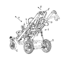
  • FIG. 1 shows the perspective representation of a stroller
  • FIG. 2 shows the rear view of the stroller according to FIG. 1 ;
  • FIG. 3 shows the perspective representation of the seat seen from below;
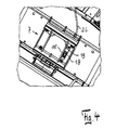
  • FIG. 4 shows a detail from FIG. 3 ;
  • FIG. 5 shows the partially opened up bottom view of the stroller
  • FIG. 6 shows another representation according to FIG. 5 ;
  • FIG. 7 shows the top view onto the underframe without a seat.
  • the wheelchair essentially consists of the underframe 1 on which the front and rear wheels 2 , 3 are fastened.
  • the seat 4 consisting of the backrest 9 and the sitting surface 6 , is inserted in a removable manner in the underframe 1 .
  • the backrest 9 is strengthened by a strut 5 .
  • the foot support 8 is fastened to the sitting surface 6 so as to be vertically adjustable.
  • the coupling 7 by way of which the seat 4 can be inserted into the seat receiving means 10 which is fastened on the underframe 1 so as to be pivotable, is fastened on the seat 4 below the sitting surface 6 .
  • the seat receiving means 10 is fastened fixedly on the transverse tube 21 , which is mounted rotatably in the underframe 1 , and consists of the rods 11 , 12 which extend transversely with respect to each other and the two steering triangles 16 which connect said rods.
  • the T-shaped lever 13 which realizes one portion 13 a which is parallel to the direction of travel F and two portions 13 b , 13 c which extend transversely thereto, is pivotably mounted in the seat receiving means 10 .
  • the lever 13 is pivotable in a clockwise manner ( FIG. 7 ) against the force of the tension spring 14 .
  • the two ends of the portions 13 b , 13 c are guided in the steering triangles 16 which are screw-connected to the ends of the rods 11 , 12 .
  • the sliding block 18 which has a bolt 15 which protrudes away from the under surface of the seat 4 , is guided in a connecting link 19 in the coupling 7 .
  • the bolt 15 abuts against the portion 13 b or the portion 13 c .
  • the sliding block 15 is connected to the rotary knob 17 by means of the first cable pull 26 .
  • the effective length of the second cable pull 22 is shortened and the sliding block 18 is pushed against the force of the spring 23 , as a result of which, by means of the bolt 15 which abuts against the portion 13 c (cf. FIG.
  • the lever 13 is pivoted, the tension spring 14 being tensioned (cf. FIG. 6 ).
  • the cable pull 22 which is supported on one of the steering triangles 16 , is fastened on the portion 13 a of the lever 13 .
  • the cable pull 22 is connected to the release lever (not shown here) of the locking element 20 , which is a telescopic cylinder which operates according to the Wrap-around principle, as is described, for example, in EP 0 628 448 B1. If the release element (not shown) is actuated, the telescopic cylinder can be extended.
  • the piston rod 24 is connected at its one end to a lever 27 which is fastened on the transverse rod 21 which is mounted rotatably in the underframe 1 . If the seat inserted into the seat receiving means 10 is pivoted, the transverse rod 21 is rotated and the piston rod 24 is pushed into the cylinder 20 or out of the cylinder.
  • FIGS. 5 and 6 show the lever 13 from the bottom view of the stroller such that the lever 13 , when the rotary element 17 is rotated, rotates in a counterclockwise manner.
  • FIG. 5 shows the locked position of the seat and FIG. 6 shows the position in which the locking element 20 is released such that manual pivoting of the seat 4 is possible.
  • the inclination of the backrest 9 in relation to the sitting surface 6 is also adjustable.
  • the sliding bracket 25 the height of which can be adapted to the anatomy of the person pushing the wheelchair, is arranged on the underframe 1 so as to be pivotable.
Landscapes

  • Engineering & Computer Science (AREA)
  • Chemical & Material Sciences (AREA)
  • Combustion & Propulsion (AREA)
  • Transportation (AREA)
  • Mechanical Engineering (AREA)
  • Health & Medical Sciences (AREA)
  • Public Health (AREA)
  • Carriages For Children, Sleds, And Other Hand-Operated Vehicles (AREA)
  • Handcart (AREA)
  • Seats For Vehicles (AREA)

Abstract

A stroller for disabled children, having a foldable underframe and a seat receiving means fixed to the underframe for receiving a seat with a backrest. The seat is fastened in the seat receiving means facing toward or away from the direction of travel. The seat receiving means is pivotable in relation to a horizontal plane for adjusting the inclination of the seat and is lockable in its respective position in relation to the underframe. The pivoting of the seat receiving means is provided by a pivoting device, which includes a control element, a locking element, and an actuator, which is in operative connection with the control element and the locking element.

Description

TECHNICAL FIELD
The invention relates to a stroller having the following features:
    • a) a foldable underframe,
    • b) a seat receiving means which is fixed to the underframe for receiving a seat with a backrest,
    • c) the seat is able to be fastened in the seat receiving means as an alternative in the direction of travel F or against the direction of travel F,
    • d) the seat receiving means is
      • d1) arranged on the underframe so as to be pivotable in relation to the horizontal H for adjusting the inclination of the seat,
      • d2) lockable in its respective position in relation to the underframe,
    • e) the pivoting of the seat receiving means is effected by means of a pivoting device,
    • f) the pivoting device includes a control element, a locking element and an actuator which is in operative connection with the control element and the locking element.
BACKGROUND
Such a stroller is marketed under the name of “Kimba Spring” by Otto Bock as a stroller for disabled children.
US 2008/0224430 A1 discloses a stroller for very small children where a trough-shaped attachment can be inserted into an underframe.
The angle of inclination of the attachment, which said attachment assumes in the underframe, is adjustable.
U.S. Pat. No. 6,086,086 discloses a stroller for disabled children with an adjustable seat frame for disabled children. The underframe, on which the seat frame can be placed, is foldable.
Strollers used in the disabled sector are subject to a series of requirements in order to be able to enable optimum adaptation to the disabled child. Whilst the age range of children who are pushed in a stroller in general is limited to a few years, the age range of disabled children who use the same wheelchair is between 1 and approximately 12 years old. The seat, consisting of the sitting surface and the backrest, can be adapted precisely to the individual body proportions of the disabled child and consequently provides the best possible support. Seat depth, seat width, backrest height and footrest height are able to be adjusted steplessly many times. Adjustable pelvic supports and lateral defining supports enable an optimum position. So that, when pushing, eye contact can be maintained at all times with the child, the seat can be removed from the underframe and placed back on the underframe facing against the direction of travel. The inclination of the seat (tilt) can be adjusted from an active sitting posture through to the relaxation position where the child is lying. So that the stroller can be transported easily in a motor vehicle, it can be collapsed or folded up. In order to be able to detach the seat from the underframe, a seat receiving means is provided into which the seat can be clicked by means of a coupling and can be locked therein.
In order to be able to adjust the inclination of the seat, the seat receiving means is fastened on the underframe so as to be pivotable. The locking of the seat can be released by means of a release device which is fastened to the sliding bracket of the underframe and the angle of the seat can be adjusted. A disadvantage in this case is that the operator has to perform the unlocking with one hand and at the same time has to hold the seat securely with the other hand so that it does not pivot uncontrollably—in particular when the child is in the seat. Handling is consequently awkward and sometimes has to be undertaken by two persons, in particular in the case of larger and consequently heavier children.
Proceeding from said problem definition, the adjusting of the inclination of the seat in relation to the horizontal is to be simplified.
SUMMARY
To solve the problem, the afore-described stroller is distinguished by the following features:
    • g) the control element is arranged on the backrest,
    • h) the locking element is arranged on the underframe,
    • i) the actuator is incorporated into the seat receiving means.
By the control element being connected directly to the seat, the operator is also able to support the seat with the same hand with which he releases the locking element and is then able to perform the adjusting of the seat inclination one-handedly and to bring about the locking of the seat again without having to interrupt the supporting force.
The actuator is preferably a lever which is arranged on the underframe so as to be pivotable against the force of a spring, the pivoting movement of said lever preferably being introducible in particular by means of the control element.
If the control element is a rotary knob, handling is further simplified. The rotary knob can then be connected to the lever by means of a first cable pull and the actuator can then preferably be connected to the locking element in particular by means of a second cable pull.
A structurally particularly simple development is possible when at the end of the first cable pull facing away from the control element, a sliding block, which abuts against the lever, is slidingly guided in the seat under the sitting surface.
The lever is preferably realized in a substantially T-shaped manner such that it forms one portion pointing parallel to the direction of travel and two portions pointing transversely to the direction of travel and the sliding block abuts against one of the portions pointing transversely to the direction of travel in dependence on the direction of installation of the seat (facing in the direction of travel or facing against the direction of travel).
The locking element is preferably a telescopic device which operates according to the wrap-around principle, as is known for example from EP 0 628 448 B1, or is distributed as a telescopic cylinder.
BRIEF DESCRIPTION OF THE DRAWINGS
An exemplary embodiment of the invention is to be described below by way of a drawing, in which, in more detail:
FIG. 1—shows the perspective representation of a stroller;
FIG. 2—shows the rear view of the stroller according to FIG. 1;
FIG. 3—shows the perspective representation of the seat seen from below;
FIG. 4—shows a detail from FIG. 3;
FIG. 5—shows the partially opened up bottom view of the stroller;
FIG. 6—shows another representation according to FIG. 5;
FIG. 7—shows the top view onto the underframe without a seat.
DETAILED DESCRIPTION
The wheelchair essentially consists of the underframe 1 on which the front and rear wheels 2, 3 are fastened. The seat 4, consisting of the backrest 9 and the sitting surface 6, is inserted in a removable manner in the underframe 1. The backrest 9 is strengthened by a strut 5. The foot support 8 is fastened to the sitting surface 6 so as to be vertically adjustable. The coupling 7, by way of which the seat 4 can be inserted into the seat receiving means 10 which is fastened on the underframe 1 so as to be pivotable, is fastened on the seat 4 below the sitting surface 6. The seat receiving means 10 is fastened fixedly on the transverse tube 21, which is mounted rotatably in the underframe 1, and consists of the rods 11, 12 which extend transversely with respect to each other and the two steering triangles 16 which connect said rods. The T-shaped lever 13, which realizes one portion 13 a which is parallel to the direction of travel F and two portions 13 b, 13 c which extend transversely thereto, is pivotably mounted in the seat receiving means 10. The lever 13 is pivotable in a clockwise manner (FIG. 7) against the force of the tension spring 14. The two ends of the portions 13 b, 13 c are guided in the steering triangles 16 which are screw-connected to the ends of the rods 11, 12.
The sliding block 18, which has a bolt 15 which protrudes away from the under surface of the seat 4, is guided in a connecting link 19 in the coupling 7. Depending on whether the seat 4 is inserted into the seat receiving means 7 facing in the direction of travel F or facing against the direction of travel F, the bolt 15 abuts against the portion 13 b or the portion 13 c. The sliding block 15 is connected to the rotary knob 17 by means of the first cable pull 26. When the rotary knob 17 is rotated, the effective length of the second cable pull 22 is shortened and the sliding block 18 is pushed against the force of the spring 23, as a result of which, by means of the bolt 15 which abuts against the portion 13 c (cf. FIG. 5), the lever 13 is pivoted, the tension spring 14 being tensioned (cf. FIG. 6). The cable pull 22, which is supported on one of the steering triangles 16, is fastened on the portion 13 a of the lever 13. By way of its other end, the cable pull 22 is connected to the release lever (not shown here) of the locking element 20, which is a telescopic cylinder which operates according to the Wrap-around principle, as is described, for example, in EP 0 628 448 B1. If the release element (not shown) is actuated, the telescopic cylinder can be extended. For this purpose, the piston rod 24 is connected at its one end to a lever 27 which is fastened on the transverse rod 21 which is mounted rotatably in the underframe 1. If the seat inserted into the seat receiving means 10 is pivoted, the transverse rod 21 is rotated and the piston rod 24 is pushed into the cylinder 20 or out of the cylinder.
If, once the desired seat inclination has been set, the rotary knob 17 is released, the pressure spring 23 pushes the bolt 15 and consequently the sliding block 18 back into its initial position, as a result of which the lever 13 is also rotated back into its initial position by means of the tension spring 14, such that the release element (not shown) on the telescopic cylinder 20 also springs back into its original position and further linear movement of the piston rod is prevented, as a result of which the seat is locked in its inclination.
The portions 13 b, 13 c of the lever 13 are developed such that the sliding block 18 or the bolt 15 connected to said sliding block is positioned in dependence on the direction into which the seat 4 is inserted into the seat receiving means 7 and when the rotary knob 17 is rotated, the lever 13 is always rotated in a clockwise manner (with reference to the top view of the stroller). FIGS. 5 and 6 show the lever 13 from the bottom view of the stroller such that the lever 13, when the rotary element 17 is rotated, rotates in a counterclockwise manner. FIG. 5 shows the locked position of the seat and FIG. 6 shows the position in which the locking element 20 is released such that manual pivoting of the seat 4 is possible.
The inclination of the backrest 9 in relation to the sitting surface 6 is also adjustable. The sliding bracket 25, the height of which can be adapted to the anatomy of the person pushing the wheelchair, is arranged on the underframe 1 so as to be pivotable.

Claims (20)

The invention claimed is:
1. A stroller, comprising:
a foldable underframe,
a seat receiver which is fixed to the underframe and configured to receive a seat, the seat having a backrest,
wherein the seat is configured to be fastened in the seat receiver alternatively facing in a direction of travel or facing against the direction of travel,
the seat receiver is
arranged on the underframe so as to be pivotable in relation to a horizontal direction for adjusting the inclination of the seat, and
lockable in its respective position in relation to the underframe,
the pivoting of the seat receiver is effected by a pivoting device,
the pivoting device includes a control element, a locking element and an actuator which is in operative connection with the control element and the locking element,
the control element is arranged on the backrest,
the locking element is arranged on the underframe,
and the actuator is incorporated into the seat receiver.
2. Stroller according to claim 1, wherein the actuator is a lever which is arranged on the underframe so as to be pivotable against the force of a spring.
3. Stroller according to claim 2, wherein the pivoting movement of the lever is introducible by the control element.
4. Stroller according to claim 3, wherein the control element is a rotary knob.
5. Stroller according to claim 4, wherein the rotary knob is connected to the lever by a first cable pull.
6. Stroller according to claim 5, wherein the actuator is connected to the locking element by a second cable pull.
7. Stroller according to claim 5, wherein at an end of the first cable pull facing away from the control element, a sliding block, which abuts against the lever, is slidingly guided in the seat under a sitting surface of the seat.
8. Stroller according to claim 7, wherein the lever has a substantially T-shaped construction with two portions pointing transversely to the direction of travel and the sliding block abuts against one of the two portions in dependence on a direction of installation of the seat.
9. Stroller according to claim 1, wherein the locking element is a telescopic device which operates according to a wrapped spring principle.
10. Stroller according to claim 1, wherein said stroller is a stroller for disabled children.
11. A stroller, comprising:
a seat having a backrest;
a foldable underframe;
a seat receiver fixed to the underframe and configured to receive the seat alternately facing in a direction of travel or facing against the direction of travel, the seat receiver being pivotable relative to a horizontal plane for adjusting an inclination of the seat relative to the underframe, the seat receiver being lockable in a pivoted position relative to the underframe;
a control element positioned on the backrest;
a locking element positioned on the underframe and operative to lock the seat relative to the underframe;
an actuator arranged in operative connection with the control element and the locking element, the actuator being incorporated into the seat receiver.
12. The stroller of claim 11, wherein the actuator is a lever which is pivotable against the force of a spring.
13. The stroller of claim 12, wherein the control element is operable to pivot the lever.
14. The stroller of claim 13, wherein the control element comprises a rotary knob.
15. The stroller of claim 14, wherein the rotary knob is connected to the lever by a first cable.
16. The stroller of claim 15, wherein the actuator is connected to the locking element by a second cable.
17. The stroller of claim 15, further comprising a sliding block positioned at an end of the first cable facing away from the control element, the sliding block abutting against the lever and being slidingly guided in the seat under a sitting surface of the seat.
18. The stroller of claim 17, wherein the lever comprises a substantially T-shaped construction with two portions pointing transversely to a direction of travel, and the sliding block abuts against one of the two portions depending on an installation direction of the seat.
19. The stroller of claim 11, wherein the locking element is a telescopic device operable according to a wrapped spring principle.
20. The stroller of claim 11, wherein the stroller is configured for use by disabled children.
US13/618,424 2011-09-14 2012-09-14 Stroller, especially rehab stroller Expired - Fee Related US8919808B2 (en)

Applications Claiming Priority (3)

Application Number Priority Date Filing Date Title
DE102011116098 2011-09-14
DE102011116098A DE102011116098B4 (en) 2011-09-14 2011-09-14 Strollers, especially prams
DE102011116098.5 2011-09-14

Publications (2)

Publication Number Publication Date
US20130069343A1 US20130069343A1 (en) 2013-03-21
US8919808B2 true US8919808B2 (en) 2014-12-30

Family

ID=46963366

Family Applications (1)

Application Number Title Priority Date Filing Date
US13/618,424 Expired - Fee Related US8919808B2 (en) 2011-09-14 2012-09-14 Stroller, especially rehab stroller

Country Status (5)

Country Link
US (1) US8919808B2 (en)
EP (1) EP2570325B1 (en)
CN (1) CN102991558B (en)
DE (1) DE102011116098B4 (en)
PL (1) PL2570325T3 (en)

Families Citing this family (2)

* Cited by examiner, † Cited by third party
Publication number Priority date Publication date Assignee Title
CN210494426U (en) 2019-05-08 2020-05-12 明门(中国)幼童用品有限公司 Backrest adjusting mechanism and nursing vehicle with same
CN112237085B (en) * 2019-07-16 2022-11-08 南京泉峰科技有限公司 Hand-push type power tool

Citations (17)

* Cited by examiner, † Cited by third party
Publication number Priority date Publication date Assignee Title
US4072318A (en) * 1975-10-09 1978-02-07 Eurolando Baby carriage
US4892327A (en) * 1986-12-09 1990-01-09 Jane, S.A. Foldable frames for children's pushchairs
US5028061A (en) * 1988-04-25 1991-07-02 Hestair Maclaren Limited Frame
US5246272A (en) * 1990-10-05 1993-09-21 Combi Corporation Baby carriage or the like including reclining or collapsing mechanism
EP0628448B1 (en) 1993-06-08 1998-03-04 P.L. Porter Company Precision linear mechanical lock
US6086086A (en) * 1999-05-11 2000-07-11 Sunrise Medical Hhg Inc. Stroller with tilt-in-space capability
US6176507B1 (en) * 1998-01-21 2001-01-23 Ampafrance Child's push-chair for a telescopic extendable cradle, and the corresponding cradle
US6398304B1 (en) * 2000-08-28 2002-06-04 Link Treasure Limited Highchair with an improved seat angle adjustment mechanism
US6513827B1 (en) * 1998-07-28 2003-02-04 Royalty Bugaboo Sarl Buggy
US20040189076A1 (en) * 2003-03-31 2004-09-30 Hanson Wayne H. Seating assembly for wheelchairs and strollers
US7377537B2 (en) * 2005-09-29 2008-05-27 Link Treasure Limited Adjustable seat for a baby stroller with one-handed inclination control
US20080150247A1 (en) * 2006-11-17 2008-06-26 Ilinko Ltd. Detachable connecting device for a child carrier
US20080224430A1 (en) * 2007-03-15 2008-09-18 Vegt Herman Van Der Stroller with a child seat
US7686323B2 (en) * 2007-10-19 2010-03-30 Ting-Yu Chen Baby stroller with portable cradle
US7694996B2 (en) * 2006-05-10 2010-04-13 Graco Children's Products Inc. Foldable and height-adjustable stroller
US7891696B2 (en) * 2008-06-17 2011-02-22 Hanson Wayne H Multifunctional foldable mobility base
US8251382B2 (en) * 2007-06-06 2012-08-28 Wonderland Nurserygoods Co., Ltd. Stroller and seat assembly mechanism for a stroller

Family Cites Families (4)

* Cited by examiner, † Cited by third party
Publication number Priority date Publication date Assignee Title
GB107032A (en) *
DE3532762A1 (en) * 1985-09-13 1987-03-19 Klemens Enste Child's pushchair
CA2106361C (en) * 1993-09-16 2000-11-28 Nenad B. Medjedovic Wheelchair backrest
CN2623200Y (en) * 2003-06-08 2004-07-07 新昌县青少年科技辅导员协会 Wheelchair for recuperation

Patent Citations (18)

* Cited by examiner, † Cited by third party
Publication number Priority date Publication date Assignee Title
US4072318A (en) * 1975-10-09 1978-02-07 Eurolando Baby carriage
US4892327A (en) * 1986-12-09 1990-01-09 Jane, S.A. Foldable frames for children's pushchairs
US5028061A (en) * 1988-04-25 1991-07-02 Hestair Maclaren Limited Frame
US5246272A (en) * 1990-10-05 1993-09-21 Combi Corporation Baby carriage or the like including reclining or collapsing mechanism
EP0628448B1 (en) 1993-06-08 1998-03-04 P.L. Porter Company Precision linear mechanical lock
US6176507B1 (en) * 1998-01-21 2001-01-23 Ampafrance Child's push-chair for a telescopic extendable cradle, and the corresponding cradle
US6513827B1 (en) * 1998-07-28 2003-02-04 Royalty Bugaboo Sarl Buggy
US6086086A (en) * 1999-05-11 2000-07-11 Sunrise Medical Hhg Inc. Stroller with tilt-in-space capability
US6270111B1 (en) * 1999-05-11 2001-08-07 Sunrise Medical Hhg Inc. Stroller having streamlined tilt-in-space block
US6398304B1 (en) * 2000-08-28 2002-06-04 Link Treasure Limited Highchair with an improved seat angle adjustment mechanism
US20040189076A1 (en) * 2003-03-31 2004-09-30 Hanson Wayne H. Seating assembly for wheelchairs and strollers
US7377537B2 (en) * 2005-09-29 2008-05-27 Link Treasure Limited Adjustable seat for a baby stroller with one-handed inclination control
US7694996B2 (en) * 2006-05-10 2010-04-13 Graco Children's Products Inc. Foldable and height-adjustable stroller
US20080150247A1 (en) * 2006-11-17 2008-06-26 Ilinko Ltd. Detachable connecting device for a child carrier
US20080224430A1 (en) * 2007-03-15 2008-09-18 Vegt Herman Van Der Stroller with a child seat
US8251382B2 (en) * 2007-06-06 2012-08-28 Wonderland Nurserygoods Co., Ltd. Stroller and seat assembly mechanism for a stroller
US7686323B2 (en) * 2007-10-19 2010-03-30 Ting-Yu Chen Baby stroller with portable cradle
US7891696B2 (en) * 2008-06-17 2011-02-22 Hanson Wayne H Multifunctional foldable mobility base

Also Published As

Publication number Publication date
EP2570325B1 (en) 2014-01-22
PL2570325T3 (en) 2014-07-31
DE102011116098B4 (en) 2013-11-14
DE102011116098A1 (en) 2013-03-14
CN102991558A (en) 2013-03-27
CN102991558B (en) 2016-10-26
US20130069343A1 (en) 2013-03-21
EP2570325A1 (en) 2013-03-20

Similar Documents

Publication Publication Date Title
US4229039A (en) Insert travel chair and method of transporting the handicapped
EP2090276B1 (en) Height adjustable rolling walker for transportation seating
CA2318028C (en) Combination walker and transport chair
US5195803A (en) Reclining seat back assembly for a wheelchair
US7523950B2 (en) Rolling walker
US20140327231A1 (en) Wheelchair comprising a height-adjustable and incline-adjustable seat
US2847058A (en) Folding wheel chair
US5480179A (en) Wheelchair chassis
US20070085301A1 (en) Center-of-gravity tilt-in-space wheelchair
JP3493000B2 (en) Wheelchair back recliner kit
US6994364B2 (en) Wheelchairs
WO2005044051A1 (en) Dynamic seating system for personal mobility vehicle
US8919808B2 (en) Stroller, especially rehab stroller
US7014204B2 (en) Rocking wheelchair
JP4383333B2 (en) wheelchair
WO2008103143A1 (en) Mobile support assembly
JP2001114111A (en) Handcart
US20060131833A1 (en) Wheelchairs
JP7343974B2 (en) wheelchair
US20100289254A1 (en) Pushchairs
AU2007231838A1 (en) Improved Rollator
JP3657216B2 (en) Wheelbarrow
GB2233221A (en) Reclining seat back assembly for a wheelchair
US20020096856A1 (en) Companion rider wheel chair
EP3756973B1 (en) Device for all-terrain transport of a child in a seated position

Legal Events

Date Code Title Description
AS Assignment

Owner name: OTTO BOCK MOBILITY SOLUTIONS GMBH, GERMANY

Free format text: ASSIGNMENT OF ASSIGNORS INTEREST;ASSIGNORS:SPIELMANN, CHRISTIAN;SONDERHUSKEN, JURGEN;SIGNING DATES FROM 20121106 TO 20121109;REEL/FRAME:029403/0846

STCF Information on status: patent grant

Free format text: PATENTED CASE

MAFP Maintenance fee payment

Free format text: PAYMENT OF MAINTENANCE FEE, 4TH YEAR, LARGE ENTITY (ORIGINAL EVENT CODE: M1551)

Year of fee payment: 4

FEPP Fee payment procedure

Free format text: MAINTENANCE FEE REMINDER MAILED (ORIGINAL EVENT CODE: REM.); ENTITY STATUS OF PATENT OWNER: LARGE ENTITY

LAPS Lapse for failure to pay maintenance fees

Free format text: PATENT EXPIRED FOR FAILURE TO PAY MAINTENANCE FEES (ORIGINAL EVENT CODE: EXP.); ENTITY STATUS OF PATENT OWNER: LARGE ENTITY

STCH Information on status: patent discontinuation

Free format text: PATENT EXPIRED DUE TO NONPAYMENT OF MAINTENANCE FEES UNDER 37 CFR 1.362

FP Lapsed due to failure to pay maintenance fee

Effective date: 20221230