TWM637537U - Heat dissipation device - Google Patents
Heat dissipation device Download PDFInfo
- Publication number
- TWM637537U TWM637537U TW111210505U TW111210505U TWM637537U TW M637537 U TWM637537 U TW M637537U TW 111210505 U TW111210505 U TW 111210505U TW 111210505 U TW111210505 U TW 111210505U TW M637537 U TWM637537 U TW M637537U
- Authority
- TW
- Taiwan
- Prior art keywords
- heat dissipation
- dissipation base
- heat
- dissipation device
- base
- Prior art date
Links
Images
Landscapes
- Encapsulation Of And Coatings For Semiconductor Or Solid State Devices (AREA)
- Heating, Cooling, Or Curing Plastics Or The Like In General (AREA)
- Power Steering Mechanism (AREA)
Abstract
Description
本案是有關於一種具有較佳散熱效能的散熱裝置。This case is about a heat dissipation device with better heat dissipation performance.
現下的均溫板或是熱管等散熱件是透過膠層固定於散熱基座上,散熱件的熱傳遞至散熱基座時會被膠層影響熱能的傳遞效率,進而影響散熱效能。The current heat dissipation parts such as vapor chambers or heat pipes are fixed on the heat dissipation base through an adhesive layer. When the heat of the heat dissipation element is transferred to the heat dissipation base, the heat transfer efficiency will be affected by the adhesive layer, thereby affecting the heat dissipation performance.
本案提供一種散熱裝置,其包括一散熱基座以及一均溫板,均溫板設置在散熱基座上,均溫板以雷射焊接接合於散熱基座,而與散熱基座成為一體。This case provides a heat dissipation device, which includes a heat dissipation base and a temperature equalization plate, the temperature equalization plate is arranged on the heat dissipation base, the temperature equalization plate is bonded to the heat dissipation base by laser welding, and integrated with the heat dissipation base.
基於上述,本案的散熱裝置的均溫板以雷射焊接接合於散熱基座,而與散熱基座成為一體。因此,均溫板與散熱基座之間的熱能的傳遞效率高,進而具有較佳的散熱效能。Based on the above, the vapor chamber of the heat dissipation device of the present application is joined to the heat dissipation base by laser welding, and integrated with the heat dissipation base. Therefore, the heat transfer efficiency between the vapor chamber and the heat dissipation base is high, thereby having better heat dissipation performance.
請參閱圖1至圖3,散熱裝置100包括一散熱基座110及一均溫板120。散熱基座110包括相對的一第一面112與第二面118,第一面112包括一周圍區114及凹陷於周圍區114的一凹腔116。Referring to FIGS. 1 to 3 , the
均溫板120適於跟熱源(未繪示)接觸,以將熱源的熱能帶走。均溫板120位於散熱基座110的第一面112的凹腔116內,且與周圍區114共平面,以使散熱基座110與均溫板120能夠穩定地放置,也就是說,均溫板120可以等高於周圍區114。當然,在其他實施例中,均溫板120也可以與周圍區114非共平面,例如均溫板120可以高於周圍區114。The
在本實施例中,均溫板120以雷射焊接接合於散熱基座110,而與散熱基座110成為一體。因此,均溫板120與散熱基座110之間的熱能的傳遞效率高,進而具有較佳的散熱效能。In this embodiment, the
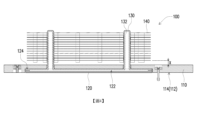
如圖4所示,均溫板120包括一內腔122及位於上表面的一接合區124,均溫板120透過接合區124雷射焊接接合至散熱基座110。搭配圖2與圖4可見,接合區124對散熱基座110的投影位於內腔122對散熱基座110的投影之外。如圖2所示,在本實施例中,接合區124例如是環型區。接合區124環繞內腔122對散熱基座110的投影。這樣的設計避免均溫板120與散熱基座110進行雷射接合時,熱熔的區域影響到內腔122。As shown in FIG. 4 , the
在一實施例中,均溫板120在內腔122的正上方的外表面與散熱基座110之間可選擇地填入散熱膠。然而,即便均溫板120在內腔122的正上方的外表面與散熱基座110之間填入散熱膠,由於均溫板120的接合區124與散熱基座110之間仍使採用雷射焊接接合,相較於習知整個均溫板與散熱基座之間均使用膠合的方式固定,本實施例的散熱裝置100在均溫板120的接合區124與散熱基座110之間仍為一體而直接導熱,因此具有較佳的散熱效果。In one embodiment, heat dissipation glue can be optionally filled between the outer surface directly above the
在一實施例中,散熱裝置100更可選擇地包括一熱管130,熱管130連接於均溫板120且穿過散熱基座110。熱管130包括一內管132,內腔122連通於內管132。因此,均溫板120的內腔122內的兩相流體可流動至熱管130的內管132。In one embodiment, the
另外,在本實施例中,散熱裝置100更包括一鰭片組140。熱管130穿設且緊配於鰭片組140。因此,由熱源的熱能可由均溫板120傳遞至散熱基座110與熱管130,再透過熱管130傳遞至鰭片組140。In addition, in this embodiment, the
如圖4所示,鰭片組140位於散熱基座110的第二面118上方,鰭片組140與散熱基座110間隔一距離X,而懸空於散熱基座110。這樣的設計可增加鰭片組140與散熱基座110之間的氣流流動空間,以提升效能。As shown in FIG. 4 , the
綜上所述,本案的散熱裝置的均溫板以雷射焊接接合於散熱基座,而與散熱基座成為一體。因此,均溫板與散熱基座之間的熱能的傳遞效率高,進而具有較佳的散熱效能。To sum up, the vapor chamber of the heat dissipation device in this case is joined to the heat dissipation base by laser welding, and integrated with the heat dissipation base. Therefore, the heat transfer efficiency between the vapor chamber and the heat dissipation base is high, thereby having better heat dissipation performance.
X:距離 100:散熱裝置 110:散熱基座 112:第一面 114:周圍區 116:凹腔 118:第二面 120:均溫板 122:內腔 124:接合區 130:熱管 132:內管 140:鰭片組 X: distance 100: cooling device 110: cooling base 112: The first side 114: surrounding area 116: concave cavity 118: The second side 120: vapor chamber 122: inner cavity 124: Junction zone 130: heat pipe 132: inner tube 140: fin group
圖1是依照本案的一實施例的一種散熱裝置的示意圖。 圖2是圖1的散熱裝置的爆炸示意圖。 圖3是圖2的另一視角的示意圖。 圖4是圖1的散熱裝置的剖面示意圖。 FIG. 1 is a schematic diagram of a heat dissipation device according to an embodiment of the present application. FIG. 2 is an exploded schematic diagram of the cooling device in FIG. 1 . FIG. 3 is a schematic diagram of another viewing angle of FIG. 2 . FIG. 4 is a schematic cross-sectional view of the heat sink in FIG. 1 .
100:散熱裝置 100: cooling device
110:散熱基座 110: cooling base
112:第一面 112: The first side
114:周圍區 114: surrounding area
116:凹腔 116: concave cavity
118:第二面 118: The second side
120:均溫板 120: vapor chamber
124:接合區 124: Junction zone
130:熱管 130: heat pipe
140:鰭片組 140: fin group
Claims (10)
Priority Applications (1)
| Application Number | Priority Date | Filing Date | Title |
|---|---|---|---|
| TW111210505U TWM637537U (en) | 2022-09-27 | 2022-09-27 | Heat dissipation device |
Applications Claiming Priority (1)
| Application Number | Priority Date | Filing Date | Title |
|---|---|---|---|
| TW111210505U TWM637537U (en) | 2022-09-27 | 2022-09-27 | Heat dissipation device |
Publications (1)
| Publication Number | Publication Date |
|---|---|
| TWM637537U true TWM637537U (en) | 2023-02-11 |
Family
ID=86689848
Family Applications (1)
| Application Number | Title | Priority Date | Filing Date |
|---|---|---|---|
| TW111210505U TWM637537U (en) | 2022-09-27 | 2022-09-27 | Heat dissipation device |
Country Status (1)
| Country | Link |
|---|---|
| TW (1) | TWM637537U (en) |
-
2022
- 2022-09-27 TW TW111210505U patent/TWM637537U/en unknown
Similar Documents
| Publication | Publication Date | Title |
|---|---|---|
| US11202390B2 (en) | Heat dissipation unit connection reinforcement structure | |
| TWI443944B (en) | Thin hot plate structure | |
| TWI684252B (en) | High temperature heat plate pedestal | |
| TWI804784B (en) | Three-dimensional heat transmission device | |
| WO2018191836A1 (en) | Flat loop heat pipe-based vapor chamber | |
| TWM562957U (en) | Combination reinforced structure of heat dissipation unit | |
| TWI815076B (en) | steam room | |
| TWM577130U (en) | Heat dissipation apparatus | |
| TWM637537U (en) | Heat dissipation device | |
| WO2019062311A1 (en) | Heat dissipation member for circuit board, and display panel using same | |
| TW201617578A (en) | Vapor chamber | |
| JP4518370B2 (en) | Ceramic susceptor support structure | |
| TWI711921B (en) | Heat dissipation device | |
| TWI701418B (en) | Heat dissipation unit connection reinforcement structure | |
| TWM636776U (en) | Three-dimensional heat transmission device | |
| US11009783B2 (en) | Liquid cooled heat dissipation module and projection device | |
| TWI853504B (en) | A manufacturing method for three dimensional vapor chamber device with thermal dissipation fin | |
| TWI620910B (en) | A three dimensional vapor chamber device | |
| TWI772822B (en) | Vapor chamber having capillary structure | |
| TW202434853A (en) | A manufacturing method for three dimensional vapor chamber device with thermal dissipation fin | |
| TW201616079A (en) | Radiator | |
| TWI738267B (en) | A dual heat transfer structure | |
| TWM456589U (en) | Heat dissipating device | |
| CN105737656B (en) | Heat-pipe radiator | |
| JPWO2022050337A5 (en) |


