JP7215869B2 - Automobile door glass run and its assembly method - Google Patents
Automobile door glass run and its assembly method Download PDFInfo
- Publication number
- JP7215869B2 JP7215869B2 JP2018197136A JP2018197136A JP7215869B2 JP 7215869 B2 JP7215869 B2 JP 7215869B2 JP 2018197136 A JP2018197136 A JP 2018197136A JP 2018197136 A JP2018197136 A JP 2018197136A JP 7215869 B2 JP7215869 B2 JP 7215869B2
- Authority
- JP
- Japan
- Prior art keywords
- glass run
- molding
- vehicle
- plate portion
- automobile door
- Prior art date
- Legal status (The legal status is an assumption and is not a legal conclusion. Google has not performed a legal analysis and makes no representation as to the accuracy of the status listed.)
- Active
Links
Images


Landscapes
- Seal Device For Vehicle (AREA)
Description
本発明は、自動車ドアのウインドフレームに配設されるグラスラン及びグラスランの組立方法に関するものである。
BACKGROUND OF THE
自動車の側部に設けられるドアとして複数のタイプがあるが、その一つとして、ウインドガラスの周縁部を保持するウインドフレームを有するドアがある。このウインドフレームを有するドアには、ウインドフレームとウインドガラスとの間をシールするためのグラスランが配設されている(例えば、特許文献1参照)。 There are several types of doors provided on the sides of automobiles, one of which is a door having a window frame that holds the peripheral edge of the window glass. A door having this window frame is provided with a glass run for sealing between the window frame and the window glass (see, for example, Patent Document 1).
特許文献1のグラスランは、ウインドフレームに対して車室外側から組み付けられるようになっている。これら文献に開示されているグラスランのようにウインドフレームに対して車室外側から組み付けられるグラスランは、ウインドフレームの一部を車室外側から覆って隠すヒドンタイプと呼ばれるものであり、例えば車両のデザイン上の要求等から採用される場合がある。
The glass run of
また、特許文献1のグラスランは、ウインドフレームの上部から車室外側へ延びるグラスラン取付板部に対して取り付けられる挿入溝を有するグラスラン本体と、このグラスラン本体の車室外側に組み付けられるモールとを備えている。また、モールは車両のデザインの一部として用いられる部材であり、一般的には、ステンレスやアルミニウム等の硬質部材で構成され、グラスラン本体に沿って車両前後方向に長く延びる形状とされている。このモールの上部及び下部には、それぞれ、車室内側へ向けて屈曲形成された上側及び下側嵌合部が設けられている。一方、グラスラン本体の車室外側には、モールの上側嵌合部及び下側嵌合部がそれぞれ嵌合する部分が、車両前後方向に延びるレール状に形成されている。さらに、このグラスラン本体の車室外側の上部には、該グラスラン本体に組み付けられたモールの上部に接触するように形成された接触部が設けられている。
Further, the glass run of
ところで、特許文献1のFIG.1~FIG.3には、グラスラン本体のレールの部分を比較的軟質な材料を使用するとともに、リップ形状にする事により、グラスラン本体に対してモールを車室外側から車室内側に、すなわち断面方向に押し込む事により組み付ける方法が開示されている。しかし、この構造および組付方法では、リップ形状としたレール状の部分が容易に撓み変形する為に、装着しやすいものの、組付後に、モールがグラスラン本体からはずれてしまう可能性もあった。 By the way, FIG. 1 to FIG. 3. By using a relatively soft material for the rail portion of the glass run main body and forming a lip shape, the molding can be pushed into the glass run main body from the outside of the vehicle interior to the inside of the vehicle interior, that is, in the cross-sectional direction. discloses a method of assembly. However, in this structure and assembly method, the lip-shaped rail-shaped portion is easily flexed and deformed, so although it is easy to install, there is a possibility that the molding will come off the glass run main body after assembly.
そこで、特許文献1のようなモールを有するグラスランを組み立てる場合において、グラスラン本体の車室外側に設けられているレール状の部分を、比較的硬質な材料で構成し、それに対してモールを長手方向(車両前後方向)にスライドさせることにより、モールの上側及び下側嵌合部をレール状の部分に嵌合させるとともに、モールとグラスラン本体との車両前後方向の位置合わせを行う方法が考えられる。
Therefore, when assembling a glass run having a molding as in
しかしながら、グラスラン本体の車室外側の上部には、組付後のモールの上部に接触する接触部が設けられており、しかも、その接触部はグラスラン本体と同様な軟質エラストマー等で構成されているので、組付時にモールをスライドさせようとしたときにモールと接触部との間に生じる摩擦力が大きくなる。このことは、モールの組付に大きな力を要するということであり、作業者が手作業でモールを組み付けることが困難になる。 However, the upper part of the glass run body on the outside of the passenger compartment is provided with a contact part that contacts the upper part of the molding after assembly, and the contact part is made of the same soft elastomer as the glass run body. Therefore, the frictional force generated between the molding and the contact portion increases when the molding is slid during assembly. This means that a large force is required to assemble the molding, making it difficult for workers to manually assemble the molding.
このことに対し、モールの上部に接触する接触部を小さくする、または無くすことが考えられるが、そのようにするとグラスラン本体とモールの上部との間に隙間ができることになり、外観見栄え上好ましくない。 In response to this, it is conceivable to reduce or eliminate the contact portion that contacts the upper part of the molding, but doing so creates a gap between the glass run body and the upper part of the molding, which is undesirable in terms of appearance. .
そこで、接触部を小さくする、または無くすことなくモールを組み付ける手段として、モールを組み付けるための機械を導入して機械による組付を行うことが考えられる。しかし、そのような機械は汎用性が無いので極めて高価なものになるとともに、大掛かりな装置で調整や設置も大変であり、導入すること自体が困難である。 Therefore, as a means of assembling the molding without reducing or eliminating the contact portion, it is conceivable to introduce a machine for assembling the molding and perform assembly by machine. However, such a machine does not have general versatility, so it is extremely expensive, and it is a large-scale device that is difficult to adjust and install, making it difficult to introduce itself.
本発明は、かかる点に鑑みてなされたものであり、その目的とするところは、モール組付用の機械を導入することなく、作業者が手作業でモールをグラスラン本体に組み付けることができるようにし、しかも、組付後において、グラスラン本体とモールとの隙間を極小化し、外観見栄えもよくすることにある。 SUMMARY OF THE INVENTION The present invention has been made in view of the above points, and an object of the present invention is to enable an operator to manually assemble a molding to a glass run body without introducing a machine for assembling the molding. In addition, after assembly, the gap between the glass run body and the molding is minimized, and the external appearance is improved.
上記目的を達成するために、第1の発明は、自動車ドアのウインド開口を形成するように延びるウインドフレームに車室外側から組み付けられ、該ウインドフレームとウインドガラスとの間をシールする自動車ドア用グラスランにおいて、上記自動車ドア用グラスランは、上記ウインドフレームの上部から車室外側へ延びるグラスラン取付板部に対して取り付けられる挿入溝を有するグラスラン本体と、該グラスラン本体の車室外側に組み付けられ、車両前後方向に延びるモールとを備え、上記グラスラン本体は、上記グラスラン取付板部の上面に沿って延びる上板部と、上記グラスラン取付板部の下面に沿って延びる下板部と、上記上板部の車室外側の端部から上記下板部の車室外側の端部まで延びる車室外側板部とを有し、上記上板部と上記下板部との間に上記挿入溝が形成され、上記上板部、上記下板部及び上記車室外側板部は、曲げ弾性率が2000MPa以上5000MPa以下の材料で構成され、上記モールの上部及び下部には、上記グラスラン本体の車室外側に嵌合する上部及び下部モール側嵌合部が車両前後方向に延びるように形成され、上記グラスラン本体の車室外側には、上記上部及び下部モール側嵌合部が嵌合する本体側嵌合部が車両前後方向に延びるように形成されるとともに、上記モールにおける車室外面の上部モール側嵌合部に接触する弾性材からなる上側接触部が形成され、さらに、上記グラスラン本体の車室外側には、上記モールにおける上記上部及び下部モール側嵌合部の間の車室内面に接触する突起が車室外側に向けて突設され、該突起は、曲げ弾性率が2000MPa以上5000MPa以下の材料で構成され、上記上側接触部における上記モールに接触する部分は被膜を有しており、該被膜は、上記モールに対する動摩擦係数が該上側接触部における該被膜によって覆われた部分を構成する弾性材よりも低く設定されていることを特徴とする。 In order to achieve the above object, the first invention provides an automobile door which is assembled from the outside of the vehicle to a window frame extending to form a window opening of the automobile door, and which seals between the window frame and the window glass. The glass run for an automobile door includes a glass run body having an insertion groove attached to a glass run mounting plate portion extending from the upper portion of the window frame toward the vehicle interior side, and the glass run body assembled to the vehicle exterior side of the vehicle. The glass run main body includes an upper plate portion extending along the upper surface of the glass run mounting plate portion, a lower plate portion extending along the lower surface of the glass run mounting plate portion, and the upper plate portion. a vehicle exterior side plate portion extending from the vehicle exterior side end of the vehicle exterior side to the vehicle exterior side end of the bottom plate portion, wherein the insertion groove is formed between the top plate portion and the bottom plate portion, The upper plate portion, the lower plate portion, and the exterior side plate portion are made of a material having a bending elastic modulus of 2000 MPa or more and 5000 MPa or less, and the upper portion and the lower portion of the molding are fitted to the exterior side of the glass run body. The upper and lower molding side fitting portions are formed to extend in the longitudinal direction of the vehicle. An upper contact portion is formed so as to extend in the front-rear direction and is made of an elastic material and is in contact with an upper molding-side fitting portion of the outer surface of the casing of the molding . A protrusion that contacts the inner surface of the vehicle interior between the upper and lower molding side fitting portions of the molding protrudes toward the outside of the vehicle interior, and the protrusion is made of a material having a bending elastic modulus of 2000 MPa or more and 5000 MPa or less. A portion of the upper contact portion that contacts the molding has a coating, and the coating has a coefficient of dynamic friction with respect to the molding that is lower than that of the elastic material forming the portion of the upper contact portion covered by the coating. It is characterized by being set.
この構成によれば、グラスラン本体にモールを組み付ける際には、グラスラン本体の車室外側にある本体側嵌合部に対して、モールの上部及び下部モール側嵌合部をその車両前後方向一端部から嵌合させる。そして、モールに対してグラスラン本体を車両前後方向にスライドさせる。このとき、グラスラン本体の上側接触部はモールに対する動摩擦係数が上側接触部よりも低い被膜を有しているので、モールが被膜に摺接した際に摺動抵抗が低くなる。よって、作業者が手作業によってモールをグラスラン本体に容易に組み付けることが可能になるので、モール組付用の機械の導入が不要になる。 According to this configuration, when the molding is assembled to the glass run main body, the upper and lower molding side fitting portions of the molding are attached to the main body side fitting portion of the glass run body on the outside of the passenger compartment. Mating from Then, the glass run body is slid in the longitudinal direction of the vehicle with respect to the molding. At this time, since the upper contact portion of the glass run body has a film having a lower coefficient of dynamic friction with respect to the molding than the upper contact portion, sliding resistance is reduced when the molding comes into sliding contact with the film. As a result, the operator can easily assemble the molding to the glass run body by hand, thus eliminating the need to introduce a machine for assembling the molding.
また、上板部、下板部及び車室外側板部が高い剛性を有することになるので、グラスラン取付板部に対するグラスラン本体の固定強度が高まる。 Further, since the upper plate portion, the lower plate portion, and the outer side plate portion have high rigidity, the fixing strength of the glass run main body to the glass run mounting plate portion is increased.
また、モールをグラスラン本体に対してスライドさせる際に、モールの車室内面と、グラスラン本体との間の接触面積が低減する。 Also, when the molding is slid relative to the glass run body, the contact area between the interior surface of the molding and the glass run body is reduced.
第2の発明は、第1の発明において、上記グラスラン本体の車室外側の上部には、自動車の車体に接触することによって車室外側に向けて撓む上側シールリップが上方へ突出するように設けられ、上記上側シールリップの基端部における車室外側に上記上側接触部が車室外側へ突出するように設けられていることを特徴とする。 According to a second aspect of the invention, in the first aspect, an upper seal lip that bends toward the outside of the vehicle upon contact with the vehicle body projects upward from the upper portion of the glass run body on the outside of the vehicle. and the upper contact portion is provided outside the vehicle at the base end portion of the upper seal lip so as to protrude toward the outside of the vehicle.
この構成によれば、自動車用ドアを閉じると、グラスラン本体の上側シールリップが自動車の車体に接触して車室外側に向けて撓むように弾性変形するので、ウインドフレームと車体との間をシールすることができる。このとき、上側シールリップの厚肉基端部の車室外側に上側接触部が設けられているので、上側シールリップの撓み変形によって上側接触部も車室外側に若干量変位し、これにより、上側接触部がモールにおける車室外面の上部により接触する。 According to this configuration, when the automobile door is closed, the upper seal lip of the glass run body comes into contact with the automobile body and is elastically deformed so as to bend toward the outside of the cabin, thereby sealing between the window frame and the car body. be able to. At this time, since the upper contact portion is provided on the outer side of the passenger compartment at the thick base end portion of the upper seal lip, the upper contact portion is also slightly displaced toward the outer side of the passenger compartment due to the bending deformation of the upper seal lip. The upper contact portion makes contact with the upper portion of the outer surface of the passenger compartment at the molding.
第3の発明は、第1または2の発明において、上記グラスラン本体の車室外側には、上記上側接触部から下方に離れた部分に、上記モールにおける車室外面の下部モール側嵌合部に接触する弾性材からなる下側接触部が形成され、上記下側接触部における上記モールに接触する部分は被膜を有しており、該被膜は、上記モールに対する動摩擦係数が該下側接触部における該被膜によって覆われた部分を構成する弾性材よりも低く設定されていることを特徴とする。 In a third aspect of the invention, in the first or second aspect, the glass run body has a portion spaced downward from the upper contact portion on the exterior side of the vehicle interior, and a lower molding side fitting portion of the outer surface of the molding on the exterior surface of the vehicle interior. A lower contact portion made of a contacting elastic material is formed, and a portion of the lower contact portion that contacts the molding has a coating, and the coating has a dynamic friction coefficient with respect to the molding at the lower contact portion. It is characterized in that it is set lower than the elastic material forming the portion covered with the film.
この構成によれば、グラスラン本体の下側接触部がモールの車室外面の下部に接触することで、モールの下部とグラスラン本体との間の隙間が無くなる。この場合に、グラスラン本体の下側接触部はモールに対する動摩擦係数が下側接触部より低い被膜を有しているので、モールが被膜に摺接した際に摺動抵抗が低くなる。よって、モールをグラスラン本体に容易に組み付けることが可能になる。 According to this configuration, the lower contact portion of the glass run main body contacts the lower portion of the outer surface of the casing of the molding, thereby eliminating the gap between the lower portion of the molding and the glass run main body. In this case, since the lower contact portion of the glass run body has a film having a lower coefficient of dynamic friction with respect to the molding than the lower contact portion, the sliding resistance is reduced when the molding is in sliding contact with the film. Therefore, it becomes possible to easily assemble the molding to the glass run body.
第4の発明は、第1から3のいずれか1つの発明において、上記被膜の厚さは、0.005mm以上0.5mm以下に設定されていることを特徴とする。 A fourth invention is characterized in that in any one of the first to third inventions, the thickness of the coating is set to 0.005 mm or more and 0.5 mm or less.
この構成によれば、被膜の厚さを0.005mm以上確保することで、モールに対する摺動抵抗が十分に低減される。また、被膜の厚さを0.5mm以下にすることで、被膜を有していることによる上側接触部の柔軟性低下が抑制される。下側接触部の被膜の厚さも同様に設定することができる。 According to this configuration, the sliding resistance to the molding can be sufficiently reduced by ensuring a thickness of 0.005 mm or more for the coating. In addition, by setting the thickness of the coating to 0.5 mm or less, the decrease in flexibility of the upper contact portion due to the presence of the coating is suppressed. The thickness of the coating on the lower contact portion can be similarly set .
第5の発明は、第4の発明において、上記車室外側板部に上記本体側嵌合部が一体成形されていることを特徴とする。 According to a fifth invention, in the fourth invention, the main body side fitting portion is integrally formed with the vehicle exterior side plate portion.
この構成によれば、グラスラン本体に対するモールの固定強度が高まる。 According to this configuration, the fixing strength of the molding to the glass run body is increased.
第6の発明は、第1から5のいずれか1つの発明において、上記被膜の上記モールに対する動摩擦係数は、0.5以下に設定されていることを特徴とする。 A sixth invention is characterized in that in any one of the first to fifth inventions, a dynamic friction coefficient of the coating with respect to the molding is set to 0.5 or less.
この構成によれば、モールの摺動抵抗が十分に小さくなる。 With this configuration, the sliding resistance of the molding is sufficiently reduced .
第7の発明は、自動車ドアのウインド開口を形成するように延びるウインドフレームに車室外側から組み付けられ、該ウインドフレームとウインドガラスとの間をシールする自動車ドア用グラスランの組立方法において、上記ウインドフレームの上部から車室外側へ延びるグラスラン取付板部に取り付けられる挿入溝を有するグラスラン本体と、該グラスラン本体の車室外側に組み付けられ、車両前後方向に延びるモールとを用意し、上記モールの上部及び下部には、上記グラスラン本体の車室外側に嵌合する上部及び下部モール側嵌合部が車両前後方向に延びるように形成しておき、上記グラスラン本体の車室外側には、上記上部及び下部モール側嵌合部が嵌合する本体側嵌合部を車両前後方向に延びるように形成するとともに、上記モールにおける車室外面の上部モール側嵌合部に接触する弾性材からなる上側接触部を形成するとともに、該上側接触部における上記モールに接触する部分が被膜を有するように構成しておき、上記被膜の上記モールに対する動摩擦係数を、該上側接触部における該被膜によって覆われた部分を構成する弾性材よりも低くしておき、上記モールの上部及び下部モール側嵌合部を、その長手方向一端部から、上記グラスラン本体の本体側嵌合部の長手方向一端部に嵌合させた後、上記モールを上記グラスラン本体に対して長手方向にスライドさせて上記グラスラン本体に対して組み付けるスライド組付工程を備えていることを特徴とする。 According to a seventh aspect of the present invention, there is provided a method for assembling an automobile door glass run which is assembled to a window frame extending so as to form a window opening of the automobile door from the outside of the passenger compartment and seals between the window frame and the window glass, wherein the window A glass run body having an insertion groove attached to a glass run mounting plate extending from the upper part of the frame toward the vehicle exterior side, and a molding assembled to the vehicle exterior side of the glass run body and extending in the longitudinal direction of the vehicle are prepared, and the upper part of the molding is provided. Upper and lower molding side fitting portions to be fitted to the exterior side of the glass run body are formed on the glass run body and the lower portion so as to extend in the longitudinal direction of the vehicle. A body-side fitting portion to which the lower molding-side fitting portion is fitted is formed so as to extend in the longitudinal direction of the vehicle, and an upper contact portion made of an elastic material that contacts the upper molding-side fitting portion on the outer surface of the vehicle interior of the molding. and a portion of the upper contact portion that contacts the molding is configured to have a coating, and the coefficient of dynamic friction of the coating with respect to the molding is determined by adjusting the portion of the upper contact portion covered by the coating to The upper and lower molding side fitting portions of the molding are fitted from one longitudinal end thereof to one longitudinal end of the main body side fitting portion of the glass run body. The method further comprises a slide assembling step of sliding the molding in the longitudinal direction with respect to the glass run body and assembling the molding with the glass run body.
第8の発明は、第7の発明において、上記モールは、上記ウインドフレームの上部の形状に沿うようにあらかじめ湾曲させておき、上記グラスラン本体は、直線形状としておき、その後、上記スライド組付工程を行うことを特徴とする。 In an eighth aspect based on the seventh aspect, the molding is curved in advance so as to follow the shape of the upper portion of the window frame, the glass run body is linear, and then the slide assembly step is performed. characterized by performing
第1の発明によれば、モールに上部及び下部モール側嵌合部を車両前後方向に延びるように形成し、グラスラン本体の車室外側に上部及び下部モール側嵌合部が嵌合する本体側嵌合部を車両前後方向に延びるように形成するとともに、モールにおける車室外面の上部モール側嵌合部に接触する弾性材からなる上側接触部を形成し、この上側接触部におけるモールに接触する部分が、モールに対する動摩擦係数が上側接触部より低い被膜を有しているので、モール組付用の機械を導入することなく、作業者が手作業によってモールをグラスラン本体に容易に組み付けることができる。 According to the first invention, the upper and lower molding side fitting portions are formed in the molding so as to extend in the longitudinal direction of the vehicle, and the body side where the upper and lower molding side fitting portions are fitted to the outside of the vehicle interior of the glass run body. The fitting portion is formed to extend in the longitudinal direction of the vehicle, and an upper contact portion made of an elastic material is formed in contact with the upper molding-side fitting portion of the molding on the outer surface of the vehicle compartment, and the upper contact portion contacts the molding. Since the portion has a film with a lower coefficient of dynamic friction with respect to the molding than the upper contact portion, the operator can easily assemble the molding to the glass run body manually without introducing a machine for assembling the molding. .
また、グラスラン取付板部に対するグラスラン本体の固定強度を高めることができる。 Also, the fixing strength of the glass run main body to the glass run mounting plate portion can be increased.
また、モールをグラスラン本体に組み付ける際に要する力をより一層低減することができる。 Also, the force required to assemble the molding to the glass run body can be further reduced.
第2の発明によれば、グラスラン本体の車室外側の上部に上側シールリップを設け、上側シールリップの厚肉基端部における車室外側に上側接触部を設けたので、自動車用ドアを閉じた状態で上側接触部をモールにおける車室外面の上部により接触させることができ、外観見栄えを良好にすることができる。 According to the second invention, the upper seal lip is provided on the upper part of the glass run body on the exterior side of the vehicle, and the upper contact portion is provided on the exterior side of the vehicle at the thick base end of the upper seal lip, so that the vehicle door is closed. In this state, the upper contact portion can be brought into contact with the upper portion of the outer surface of the vehicle interior of the molding, and the external appearance can be improved.
第3の発明によれば、グラスラン本体の車室外側に、モールにおける車室外面の下部に接触する弾性材からなる下側接触部を形成することで、モールの下部とグラスラン本体との間の隙間が無くなり、外観見栄えを良好にすることができる。この場合に、下側接触部におけるモールに接触する部分がモールに対する動摩擦係数が下側接触部より低い被膜を有しているので、作業者が手作業によってモールをグラスラン本体に容易に組み付けることができる。 According to the third aspect of the present invention, a lower contact portion made of an elastic material that contacts the lower part of the outer surface of the casing of the molding is formed on the exterior side of the glass run body, whereby the lower part of the molding and the glass run body are formed. The gap is eliminated, and the external appearance can be improved. In this case, since the portion of the lower contact portion that contacts the molding has a film having a lower coefficient of dynamic friction with respect to the molding than the lower contact portion, an operator can easily assemble the molding to the glass run body by hand. can.
第4の発明によれば、被膜の厚さを0.005mm以上確保することで、モールに対する摺動抵抗を十分に低減することができる。また、被膜の厚さを0.5mm以下にすることで、被膜を有していることによる上側接触部の柔軟性低下を抑制することができる。 According to the fourth invention, by ensuring the thickness of the film to be 0.005 mm or more, the sliding resistance to the molding can be sufficiently reduced. Further, by setting the thickness of the coating to 0.5 mm or less, it is possible to suppress deterioration in the flexibility of the upper contact portion due to the presence of the coating .
第5の発明によれば、グラスラン本体に対するモールの固定強度を高めることができる。 According to the fifth invention, the fixing strength of the molding to the glass run body can be increased.
第6の発明によれば、モールの摺動抵抗を十分に小さくすることができ、作業者が手作業によってモールをグラスラン本体に対してより一層容易に組み付けることができる。 According to the sixth invention, the sliding resistance of the molding can be sufficiently reduced, and the operator can manually assemble the molding to the glass run body more easily .
第7の発明によれば、モール組付用の機械を導入することなく、作業者が手作業によってモールをグラスラン本体に容易に組み付けることができる。 According to the seventh invention, the operator can easily assemble the molding to the glass run body manually without introducing a machine for assembling the molding.
第8の発明によれば、モールがあらかじめ湾曲していて、グラスラン本体が直線形状である場合に摺動抵抗を低減できるので、モールをグラスラン本体に組み付ける際に要する力を低減することができる。 According to the eighth invention, when the molding is curved in advance and the glass run body is straight, the sliding resistance can be reduced, so that the force required to assemble the molding to the glass run body can be reduced.
以下、本発明の実施形態を図面に基づいて詳細に説明する。尚、以下の好ましい実施形態の説明は、本質的に例示に過ぎず、本発明、その適用物或いはその用途を制限することを意図するものではない。 BEST MODE FOR CARRYING OUT THE INVENTION Hereinafter, embodiments of the present invention will be described in detail based on the drawings. It should be noted that the following description of preferred embodiments is essentially merely illustrative, and is not intended to limit the invention, its applications, or its uses.
(実施形態1)
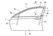
図1は、本発明の実施形態1に係る左側フロントドア用グラスラン(自動車ドア用グラスラン)10を備えた左側フロントドア(自動車ドア)1を車室外側(左側)から見た側面図である。この左側フロントドア1は、自動車(図示せず)の左側において前側に配設され、自動車の左側において前側に形成された開口部(図示せず)を開閉する。右側フロントドアは図示しないが左側フロントドアと対称に設けられている。また、図示しないが、左右のリヤドアにも本発明に係る自動車ドア用グラスランを設けることができる。
(Embodiment 1)
FIG. 1 is a side view of a left front door (automobile door) 1 provided with a left front door glass run (automobile door glass run) 10 according to
尚、この実施形態の説明では、車両前側を単に「前」といい、車両後側を単に「後」というものとする。 In the description of this embodiment, the vehicle front side is simply referred to as "front", and the vehicle rear side is simply referred to as "rear".
(ドアの構造)
図1に示すように、左側フロントドア1は、該左側フロントドア1の略下半部を構成するドア本体2と、略上半部を構成するウインドフレーム3とを有している。ドア本体2の前端部は、図示しないが、上下方向に延びる回動軸を有するヒンジを介して車体のピラーに取り付けられている。ドア本体2は、鋼板等からなるインナパネル(図示せず)とアウタパネル2aとで構成されており、内部には、昇降動作するウインドガラス4や、ウインドガラス4を昇降動作させるための昇降装置(図示せず)等が収容可能になっている。
(door structure)
As shown in FIG. 1, the left
ウインドフレーム3は、ウインドガラス4の周縁部を保持するサッシュとして機能するものであり、ウインド開口7を形成するように延びている。ウインドフレーム3によって形成されているウインド開口7がウインドガラス4によって開閉されるようになっている。この実施形態のウインドフレーム3は、図2に示すように鋼板等をプレス成形してなるアウタパネル材5及びインナパネル材6を組み合わせて構成されたものである。尚、ウインドフレーム3は、例えばロール成形法によって構成されたものであってもよい。
The
図1に示すように、ウインドフレーム3は、フレーム上辺部3aとフレーム後辺部3bとで構成されている。フレーム上辺部3aは、ドア本体2の上縁における前部から後側へ延びており、後端に近づくほど上に位置するように湾曲している。フレーム後辺部3bは、ドア本体2の上縁における後部から上方へ延びている。フレーム後辺部3bの上端部と、フレーム上辺部3aの後端部とが接続されてウインドフレーム3が構成されている。
As shown in FIG. 1, the
尚、ウインドフレーム3の形状は図示した形状に限られるものではなく、全体的に上方へ向けて湾曲した形状であってもよいし、湾曲部の位置やフレーム上辺部3aの傾斜角度曲率も車体のルーフ形状に対応するように任意に設定することができる。また、ウインドフレーム3の前部に上下方向に延びるフレーム前辺部(図示せず)を設けてもよい。また、ウインドフレーム3の前部には、ドアミラー(図示せず)が取り付けられるドアミラー取付部3dが設けられている。
The shape of the
図2に示すように、ウインドフレーム3のフレーム上辺部3aには、車室外側へ延びるグラスラン取付板部8が形成されている。グラスラン取付板部8は、アウタパネル材5及びインナパネル材6の車室外側部分で構成されている。すなわち、アウタパネル材5の車室外側部分は略水平に延びるとともに前後方向に連続して延びている。インナパネル材6の車室外側部分も略水平に延びるとともに前後方向に連続して延びている。アウタパネル材5の車室外側部分の上面に、インナパネル材6の車室外側部分の下面を重ね合わせることでグラスラン取付板部8が構成されている。尚、グラスラン取付板部8は、アウタパネル材5及びインナパネル材6の両方で構成する以外にも、アウタパネル材5及びインナパネル材6の一方のパネル材で構成することができる。
As shown in FIG. 2, the
(自動車ドア用グラスランの構成)
左側フロントドア用グラスラン10は、ウインドフレーム3の少なくとも車室外側を覆い隠す、いわゆるヒドンタイプであり、詳細は後述するが、ウインドフレーム3のフレーム上辺部3aに対して車室外側から組み付けられ、ウインドフレーム3とウインドガラス4との間をシールするためのシール材として機能する。左側フロントドア用グラスラン10は、ウインドフレーム3の車室外側部分であるグラスラン取付板部8も覆うように形成されている。
(Structure of Glass Run for Automobile Door)
The left front
図1に示すように、左側フロントドア用グラスラン10は、グラスラン上辺部11と、グラスラン前側縦辺部12と、グラスラン後側縦辺部13とを備えている。グラスラン上辺部11、グラスラン前側縦辺部12及びグラスラン後側縦辺部13は一体化されている。グラスラン上辺部11は、ウインドフレーム3の上部であるフレーム上辺部3aに沿って前後方向に延びており、グラスラン取付板部8に組み付けられた状態でフレーム上辺部3aに沿って湾曲しており、後端に近づくほど上に位置するように配設される。
As shown in FIG. 1 , the left front
グラスラン前側縦辺部12は、グラスラン上辺部11の前端部から下方に延びている。グラスラン後側縦辺部13は、グラスラン上辺部11の後端部から下方へ延びている。グラスラン前側縦辺部12及びグラスラン後側縦辺部13の下側は、ドア本体2の内部に達するまで延びており、これらグラスラン前側縦辺部12及びグラスラン後側縦辺部13により、ウインドガラス4の前部及び後部がそれぞれ上下方向に案内される。
The glass run front
図2に示すように、左側フロントドア用グラスラン10は、グラスラン取付板部8が挿入される挿入溝14を有するグラスラン本体20と、該グラスラン本体20の車室外側に組み付けられ、前後方向に延びるモール30とを備えている。モール30は、グラスラン上辺部11を構成するグラスラン本体20にのみ組み付けられており、グラスラン前側縦辺部12及びグラスラン後側縦辺部13にはモール30が組み付けられないようになっている。
As shown in FIG. 2, the left front
グラスラン本体20は、グラスラン取付板部8の上面に沿って延びる上板部21と、グラスラン取付板部8の下面に沿って延びる下板部22と、上板部21の車室外側の端部から下板部22の車室外側の端部まで上下方向に延びる車室外側板部23とを有している。上板部21、下板部22及び車室外側板部23は押出成形により一体成形されている。
The glass run
上板部21と下板部22との間に、グラスラン取付板部8に対して取り付けられる挿入溝14が形成されている。挿入溝14は、上板部21の車室内側の端部と、下板部22の車室内側の端部との間に開口しており、前後方向に延びている。挿入溝14の底部は、車室外側板部23によって構成されている。グラスラン取付板部8に対してグラスラン本体20を取り付けた状態で、グラスラン取付板部8の車室外側の端部が、挿入溝14の底部近傍に達するように、挿入溝14の深さ及びグラスラン取付板部8の車室内外方向の寸法(左右方向の寸法)が設定されている。
Between the
上板部21、下板部22及び車室外側板部23は、曲げ弾性率が2000MPa以上5000MPa以下の高剛性材料で構成されている。このような高剛性材料としては、例えば硬質樹脂(例えばタルクやガラス繊維を混合したポリプロピレン)等を使用することができるが、これらに限られるものではなく、他の材料や各種複合材料等を使用することもできる。上板部21、下板部22及び車室外側板部23を上記高剛性材料で構成することにより、上板部21、下板部22及び車室外側板部23の剛性が高まり、特に上板部21及び下板部22の開きを抑制することができる。これにより、グラスラン取付板部8に対してグラスラン本体20を取り付けた状態で、グラスラン取付板部8を上板部21及び下板部22によって厚み方向にしっかりと挟持することができ、左側フロントドア用グラスラン10がグラスラン取付板部8から外れにくくなり、左側フロントドア用グラスラン10の固定強度を十分に高めることができる。
The
上板部21の下面には、下方へ突出する複数の上側係合突起21aが車室内外方向に互いに間隔をあけて形成されている。上側係合突起21aの下端部はグラスラン取付板部8の上面に接触するように形成することができる。車室内側に位置する上側係合突起21aには、グラスラン取付板部8の上面から上方へ突出する切り起こし部8aに対して車室外側から当接して係合するようになっている。これにより、左側フロントドア用グラスラン10がグラスラン取付板部8から外れにくくなる。
A plurality of upper
下板部22の上面には、上方へ突出する複数の下側係合突起22aが車室内外方向に互いに間隔をあけて形成されている。下側係合突起22aの上端部はグラスラン取付板部8の下面に接触するように形成することもできる。下側係合突起22aの上端部と、上側係合突起21aの下端部との上下方向の離間距離は、グラスラン取付板部8の厚みと同程度にしてもよいし、組み付けしやすさを考慮し、若干広くしてもよい。
A plurality of lower
グラスラン本体20の車室外側の上部には、自動車の車体100に接触することによって車室外側に向けて撓む上側シールリップ24が上方へ突出するように設けられている。上側シールリップ24の基端部は、上板部21の上面の車室外側部分に固着され、一体化されている。上側シールリップ24が自動車の車体100と接触していないとき、即ち、左側フロントドア1が開状態にあるときには、図2に示すように略真上に向けて突出する形状である。一方、上側シールリップ24が自動車の車体100と接触しているとき、即ち、左側フロントドア1が閉状態にあるときには、図示しないが、車体100によって車室外側の斜め下方へ押されることによって先端部が基端部よりも車室外側に位置するように弾性変形して車体100に密着する。これにより、上側シールリップ24によるシール性が得られる。車体100は、例えばボディパネル等である。
An
グラスラン本体20の車室内側の上部には、自動車の車体100に接触することによって車室外側に向けて撓む内側シールリップ25が車室外側の斜め上方へ突出するように設けられている。内側シールリップ25の基端部は、上板部21の上面の車室内側部分に固着され、一体化されている。内側シールリップ25が自動車の車体100と接触していないとき、即ち、左側フロントドア1が開状態にあるときには、図2に示すように車室外側の斜め上方へ突出する形状である。一方、内側シールリップ25が自動車の車体100と接触しているとき、即ち、左側フロントドア1が閉状態にあるときには、図示しないが、車体100によって車室外側の斜め下方へ押されることによって先端部が上側シールリップ24の基端部に接近するように弾性変形して車体100に密着する。これにより、内側シールリップ25によるシール性が得られる。
An
また、上板部21の車室内側の端部には、内側シール部26が下方へ突出するように設けられている。内側シール部26は、上板部21の車室内側の端部に固着され、一体化されている。内側シール部26の下端部は、グラスラン取付板部8の上面に接触するようになっている。
An
グラスラン本体20の車室外側の下部には、下側シール部27が下方へ突出するように設けられている。下側シール部27の基端部は、下板部22の下面の車室外側部分に固着され、一体化されている。下側シール部27の下部は、車室内側へ向けて屈曲している。この下側シール部27の下部は、閉状態のウインドガラス4の車室外側の面に接触するようになっている。
A
グラスラン本体20の車室内側の下部には、下側シール部28が下方へ突出するように設けられている。下側シール部28の基端部は、下板部22の車室内側の端面に固着され、一体化されている。下側シール部28の下部は、車室内側へ向けて屈曲している。この下側シール部28の下部は、ウインドフレーム3のアウタパネル材5に接触するようになっている。また、下側シール部28は、閉状態のウインドガラス4の車室内側の面にも接触するようになっている。
A
下板部22の下面には、下側シール部27の基端部と、下側シール部28の基端部との間に、中間シールリップ29が設けられている。中間シールリップ29の基端部は、下板部22の下面における車室内外方向の中間部に固着され、一体化されている。中間シールリップ29は、車室外側の斜め下方へ延びるように形成されており、閉状態のウインドガラス4の上端に接触するようになっている。
An
上側シールリップ24、内側シールリップ25、内側シール部26、下側シール部27、下側シール部28及び中間シールリップ29は、上記高剛性材料からなる部材(上板部21、下板部22及び車室外側板部23)に押出成形により一体化されているので、上記高剛性材料よりも柔らかく弾性変形し易い材料で構成しても組付時の形状維持性を確保できる。
The
なお、押出成形による一体化とは、上記高剛性材料からなる部材を押出成形する際、同時に上記各種シール材(上側シールリップ24、内側シールリップ25、内側シール部26、下側シール部27、下側シール部28及び中間シールリップ29)も押出成形し、周知の押出ダイスを用いて一体化する方法や、先に上記高剛性材料からなる部材を押出成形しておき、これに上記各種シール材を押出機の押出ダイスを用いて一体化する方法など、一般に知られる工程が用いられる。
The integration by extrusion molding means that when the member made of the high-rigidity material is extruded, at the same time, the various sealing materials (
上側シールリップ24、内側シールリップ25、内側シール部26、下側シール部27、下側シール部28及び中間シールリップ29を構成する材料としては、例えばEPDM(エチレンプロピレンジエンゴム)等、各種ポリマーを主体としたゴムや、TPO(オレフィン系熱可塑性エラストマー)やTPS(スチレン系熱可塑性エラストマー)等、各種TPE(熱可塑性エラストマー)等のように、弾性を有する材料を使用することができる。上記ゴムやTPEは、発泡材であってもよいし、ソリッド材であってもよい。なお、上記高剛性材料をポリプロピレン等の硬質樹脂とした場合は、TPO等のTPEを使用するのが、好ましい。
Materials for forming the
上側シールリップ24、内側シールリップ25、内側シール部26、下側シール部27、下側シール部28及び中間シールリップ29は、上板部21、下板部22及び車室外側板部23と共に、グラスラン本体20を構成する部分である。
The
図1に示す上記モール30は、車両のデザインの一部として用いられる部材であり、一般的には、ステンレスやアルミニウム等の硬質部材で構成されている。この実施形態では、ステンレス製の板材で構成されている。モール30は、グラスラン本体20に沿って前後方向に長く延びる形状とされており、該モール30の前端部はウインドフレーム3のフレーム上辺部3aの前端部近傍に位置し、該モール30の後端部はウインドフレーム3のフレーム上辺部3aの後端部近傍に位置している。
The
図2及び図3に示すように、モール30の上部及び下部には、グラスラン本体20の車室外側に嵌合する上部及び下部モール側嵌合部31、32が前後方向に延びるように形成されている。上部モール側嵌合部31は、車室内側へ向けて折り曲げられた後、下方へ屈曲するように形成されており、下方に開放する形状となっている。下部モール側嵌合部32は、車室内側へ向けて折り曲げられた後、上方へ屈曲するように形成されており、上方に開放する形状となっている。モール30における上部モール側嵌合部31と下部モール側嵌合部32との間の部分は、意匠部33とされている。この意匠部33は、車室外側へ向けて緩やかに湾曲している。
As shown in FIGS. 2 and 3, upper and lower molding side
グラスラン本体20の車室外側には、上部モール側嵌合部31及び下部モール側嵌合部32がそれぞれ嵌合する上側本体側嵌合部23a及び下側本体側嵌合部23bが前後方向に延びるように形成されている。すなわち、グラスラン本体20の車室外側板部23の車室外面には、基部23cが車室外側へ突出するように形成されている。この基部23cは、車室外側板部23の車室外面の上下方向中央部近傍に位置付けられていて、前後方向に連続している。
An upper body-side
図4に示すように、上側本体側嵌合部23aは、基部23cの突出方向先端部から上方へ突出して前後方向に延びるように形成された板状部で構成されている。この上側本体側嵌合部23aと、車室外側板部23の車室外面との間には、モール30の上部モール側嵌合部31を構成する板材の厚みよりも広い隙間S1が形成されている。
As shown in FIG. 4, the upper main body side
また、下側本体側嵌合部23bは、基部23cの突出方向先端部から下方へ突出して前後方向に延びるように形成された板状部で構成されている。下側本体側嵌合部23bと、車室外側板部23の車室外面との間には、モール30の下部モール側嵌合部32を構成する板材の厚みよりも広い隙間S2が形成されている。
Further, the lower main body side
上側本体側嵌合部23a及び下側本体側嵌合部23bは、グラスラン本体20の前端部から後端部まで連続して延びており、後述するモール30を組み付ける際に、当該モール30を前後方向に案内するレールとしても機能するレール状部分である。
The upper main body side
図3に示すように、モール30の上部モール側嵌合部31は、グラスラン本体20の上側本体側嵌合部23aを上方から囲むように配置され、この状態で、上部モール側嵌合部31が上側本体側嵌合部23aに嵌合する。また、モール30の下部モール側嵌合部32は、グラスラン本体20の下側本体側嵌合部23bを下方から囲むように配置され、この状態で、下部モール側嵌合部32が下側本体側嵌合部23bに嵌合する。上部モール側嵌合部31及び下部モール側嵌合部32がそれぞれ上側本体側嵌合部23a及び下側本体側嵌合部23bに嵌合すると、上部モール側嵌合部31及び下部モール側嵌合部32の形状により、モール30がグラスラン本体20に対して車室内外方向及び上下方向に変位しないようになる。
As shown in FIG. 3, the upper molding side
この実施形態では、上側本体側嵌合部23a及び下側本体側嵌合部23bを車室外側板部23に一体成形しているので、上側本体側嵌合部23a及び下側本体側嵌合部23bも高剛性材料で構成することができる。よって、上部モール側嵌合部31及び下部モール側嵌合部32がそれぞれ上側本体側嵌合部23a及び下側本体側嵌合部23bに嵌合した状態で、モール30がグラスラン本体20から外れにくくなる。
In this embodiment, since the upper body side
グラスラン本体20の車室外側には、モール30における車室外面の上部に接触する弾性材からなる上側接触部40が形成されている。上側接触部40は、上側シールリップ24の基端部における車室外側の面から車室外側へ向けて突出するように設けられており、上側接触部40と、上側シールリップ24とは一体成形されている。上側接触部40は、突出方向先端側(車室外側)へ向かって先細となるように形成されており、前後方向に連続して延びている。上側接触部40の先端側の下面が、モール30に対して上方から接触し、これにより、モール30の上部とグラスラン本体20の上部との間に隙間が無くなり、外観見栄えが良好になる。
An
上側接触部40と上側シールリップ24とが厚肉基端部24aを介して一体成形されているので、上側シールリップ24が車室内外方向に弾性変形すると、上側接触部40が上側シールリップ24の変形量及び変形方向に対応して若干量変位することになる。例えば、上側シールリップ24は、上述したように左側フロントドア1が開状態にあるときには略真上に向けて突出する形状であり、このとき、上側接触部40の先端側の下面が、モール30に対して上方から接触するように、上側接触部40の位置及び形状が設定されている。また、左側フロントドア1が閉状態にあるときには上側シールリップ24が車室外側の斜め下方へ向けて倒れるように弾性変形するが、厚肉基端部24aを介しているので、上側接触部40が車室外側且つ下方へ向けて若干量変位する。これにより、上側接触部40の先端側の下面が、モール30に対して上方から若干強く接触するので、上側接触部40とモール30とをより密着させることができる。
Since the
また、グラスラン本体20の車室外側には、上側接触部40から下方に離れた部分に、モール30における車室外面の下部に接触する弾性材からなる下側接触部41が形成されている。下側接触部41は、下側シール部27の車室外側の面から車室外側へ膨出するように設けられており、下側接触部41と下側シール部27とは一体成形されている。下側接触部41は、前後方向に連続して延びている。下側接触部41が、モール30に対して下方から接触し、これにより、モール30の下部とグラスラン本体20の下部との間に隙間が無くなり、外観見栄えが良好になる。
A
下側接触部41と下側シール部27とが一体成形されており、かつ、両者はいずれも基端部27aから下方に延設されているので、下側シール部27が弾性変形すると、下側接触部41が下側シール部27の変形量及び変形方向に対応して変位することになる。例えば、下側シール部27は、上述したようにウインドガラス4が閉状態にあるときに、ウインドガラス4の車室外面に接触するので、このときに車室外側へ向けて弾性変形する場合がある。これにより、下側接触部41が車室外側に変位してモール30に対して下方から強く接触することになるので、下側接触部41とモール30とを確実に密着させることができる。
Since the
また、グラスラン本体20の車室外側には、モール30の車室内面に接触する突起23dが車室外側に向けて突設されている。突起23dがモール30の車室内面に接触することで、車室外側板部23の広い範囲がモール30に接触するのを回避することができる。突起23dは、車室外側板部23に一体成形することができる。
A
(摺動抵抗低減用の被膜)
この実施形態では、モール30をグラスラン本体20に対して一方の端部から、長手方向にスライドさせて組み付けるようにしており、この組付の際に、組付作業を作業者が手作業で行えるようにするために、モール30の摺動抵抗を低減することが可能な構成を備えている。
(Coating for reducing sliding resistance)
In this embodiment, the
すなわち、上側接触部40におけるモール30に接触する部分は、弾性を持った上側被膜40aを有している。この上側被膜40aは、モール30に対する摺動抵抗が該上側接触部40における該上側被膜40aによって覆われた部分を構成する弾性材よりも低く設定されている。具体的には、上側接触部40における上側被膜40aによって覆われた部分は、上側シールリップ24等と同様な弾性材で構成されているが、上側被膜40aは、オレフィン系樹脂にシリコンを混合することにより、動摩擦係数を、上側シールリップ24等と同様な弾性材よりも小さくした材料からなる。尚、上側被膜40aの構成する材料は、オレフィン系樹脂にシリコンを混合したもの以外であってもよい。
That is, the portion of the
上側被膜40aの動摩擦係数は0.5以下が好ましい。上側被膜40aの動摩擦係数は、混合するシリコンの量によって任意に変更することができる。一方、上側接触部40における上側被膜40aによって覆われた部分を構成する弾性材の動摩擦係数は0.6程度である。
The coefficient of dynamic friction of the
ここで、動摩擦係数の測定方法について説明する。動摩擦係数の測定方法は、特開平9-123761号公報に開示されている測定方法を利用することができ、上記動摩擦係数はこの測定方法によって得られた値である。測定機としては、新東科学株式会社製 表面性状測定機「HEIDON-14D」を用意し、板金時計皿を使用して動摩擦係数を測定した。すなわち、特開平9-123761号公報の図3に記載されているように、板金時計皿を試料の上面に対して荷重1kgfで押し付け、速度1000mm/minで板金時計皿と試料とを相対移動させることによって動摩擦係数を測定する。 Here, a method for measuring the coefficient of dynamic friction will be described. As a method for measuring the coefficient of dynamic friction, the method disclosed in Japanese Patent Application Laid-Open No. 9-123761 can be used, and the coefficient of dynamic friction is the value obtained by this measuring method. As a measuring instrument, a surface texture measuring instrument "HEIDON-14D" manufactured by Shinto Kagaku Co., Ltd. was prepared, and the dynamic friction coefficient was measured using a sheet metal watch glass. That is, as described in FIG. 3 of Japanese Patent Application Laid-Open No. 9-123761, a sheet metal watch glass is pressed against the upper surface of the sample with a load of 1 kgf, and the sheet metal watch glass and the sample are moved relative to each other at a speed of 1000 mm/min. Measure the dynamic friction coefficient by
上側被膜40aの厚さは、0.005mm以上0.5mm以下に設定されている。上側被膜40aの厚さを0.005mm以上確保することで、モール30に対する摺動抵抗が十分に低減される。また、上側被膜40aの厚さを0.5mm以下にすることで、上側被膜40aを有していることによる上側接触部40の柔軟性低下が抑制される。
The thickness of the
なお、上側被膜40aの厚さは、より好ましくは0.01mm以上0.2mm以下で、さらには0.03mm以上0.1mm以下が好ましい。上側被膜40aの厚さをこのように設定することで、摺動抵抗の十分な低減と、上側接触部40の柔軟性の維持とを両立することができる。また、上側被膜40aは、上側接触部40が押出成形される際、これと同時に一体的に押出成形することができる。一体的に押出成形することで上記した上側被膜40aの厚さを精度よくコントロールできる。なお、上側被膜40aは押出成形によらず、シート状物を貼付けたり、スプレーや刷毛などによる塗装によって成形してもよい。
The thickness of the
また、下側接触部41におけるモール30に接触する部分は下側被膜41aを有しており、該下側被膜41aは、モール30に対する動摩擦係数が該下側接触部41における該下側被膜41aによって覆われた部分を構成する弾性材よりも低く設定されている。この下側被膜41aは、上側被膜40aと同じ材料で構成されるとともに、同じ厚さに設定することもできる。また、上側被膜40aと同様な方法で下側接触部41も成形される。
A portion of the
(自動車ドア用グラスランの組立方法)
次に、上記のように構成された左側フロントドア用グラスラン10を組み立てる方法について説明する。グラスラン本体20は、ウインドフレーム3に取り付けられる前において、フレーム上辺部3aに沿って延びる部分(グラスラン上辺部11)が直線状に形成されている。一方、モール30は、ウインドフレーム3のフレーム上辺部3aに沿うようにあらかじめ湾曲形成されている。
(Method for assembling glass run for automobile door)
Next, a method for assembling the left front
そして、モール30の上部モール側嵌合部31及び下部モール側嵌合部32に対して、その長手方向一端部から、グラスラン本体20の上側本体側嵌合部23a及び下側本体側嵌合部23bの長手方向一端部を嵌合させた後、モール30に対してグラスラン本体20を長手方向にスライドさせてグラスラン本体20を組み付けるスライド組付工程を行う。
Then, the upper body side
このスライド組付工程では、始めに、モール30の上部モール側嵌合部31及び下部モール側嵌合部32の前端部に対して、グラスラン本体20の上側本体側嵌合部23a及び下側本体側嵌合部23bの後端部を嵌合させる。上部モール側嵌合部31及び下部モール側嵌合部32に対して上側本体側嵌合部23a及び下側本体側嵌合部23bを嵌合した後、モール30に対してグラスラン本体20を後側へ向けてスライドさせていく。スライドさせるとき、上述したように、モール30は湾曲しているが、グラスラン本体20のグラスラン上辺部11は直線状であるため、特に、モール30の上部モール側嵌合部31に対してグラスラン本体20の上側接触部40が強く接触する。また、モール30の下部モール側嵌合部32に対してグラスラン本体20の下側接触部41が接触することもある。
In this slide assembly process, first, the upper body
このとき、上側接触部40におけるモール30に接触する部分がモール30に対する動摩擦係数が、上側接触部40よりも低い上側被膜40aによって覆われているので、モール30の上部と、上側接触部40との間の摺動抵抗が低減する。また、下側接触部41におけるモール30に接触する部分が、モール30に対する動摩擦係数が下側接触部41よりも低い下側被膜41aによって覆われているので、モール30の下部と、下側接触部41との間の摺動抵抗も低減する。よって、作業者が手作業によってモール30に対してグラスラン本体20を容易に組み付けることが可能になるので、モール組付用の機械の導入が不要になる。モール30の前端部がグラスラン本体20のグラスラン上辺部11の前端部まで達したところでスライド動作を停止する。以上のようにしてモール30に対してグラスラン本体20を組み付けることで左側フロントドア用グラスラン10の組立作業が完了する。
At this time, since the portion of the
尚、モール30が上側に向けて湾曲しているので、モール30の上部が下部に比べてグラスラン本体20に強く接触することになる。従って、グラスラン本体20には、上側被膜40aを少なくとも設けておけばよく、下側被膜41aを省略してもよい。
Since the
また、スライド組付工程において、モール30に対してグラスラン本体20をスライドさせる方法を説明したが、その逆で、グラスラン本体20に対してモール30をスライドさせる方法でもよい。
Also, in the slide assembly process, the method of sliding the glass run
(自動車ドア用グラスランの使用時)
左側フロントドア1に左側フロントドア用グラスラン10を取り付ける際には、ウインドフレーム3のグラスラン取付板部8に対して左側フロントドア用グラスラン10を取り付けると同時に、上板部21の下側係合突起21aと、下板部22の上側係合突起22aが、それぞれ、グラスラン取付板部分8の上面側と下面側に接触する。このようにして左側フロントドア用グラスラン10が取り付けられた状態では、上板部21、下板部22及び車室外側板部23の曲げ弾性率が2000MPa以上5000MPa以下とされているので、グラスラン取付板部8に対するグラスラン本体20の固定強度が高まる。
(When using a glass run for automobile doors)
When the left front
その後、左側フロントドア1を閉じると、グラスラン本体20の上側シールリップ24及び内側シールリップ25が自動車の車体100に接触して車室外側に向けて撓むように弾性変形するので、ウインドフレーム3と車体100との間を上側シールリップ24及び内側シールリップ25によってシールすることができる。このとき、上側シールリップ24の厚肉基端部24aの車室外側に上側接触部40が設けられているので、上側シールリップ24の撓み変形によって上側接触部40も車室外側に若干量変位し、これにより、上側接触部40がモール30における車室外面の上部により接触する。よって、上側接触部40とモール30の間に隙間が無くなり、外観見栄えを良好にすることができる。
After that, when the left
(実施形態2)
図5及び図6は、本発明の実施形態2に係るものであり、この実施形態2では、モール30の組付構造が実施形態1のものとは異なっている。以下、実施形態1と同じ部分には同じ符号を付して説明を省略し、実施形態1とは異なる部分について詳細に説明する。
(Embodiment 2)
5 and 6 relate to a second embodiment of the present invention, and in this second embodiment the assembly structure of the
実施形態2では、モール30の上下方向の寸法H1が、実施形態1のモール30の上下方向の寸法に比べて長く設定されている。このように、モール30の上下方向の寸法H1が長くなると、上側本体側嵌合部23a及び下側本体側嵌合部23bの上下方向の寸法H2も広げる必要があるが、上側本体側嵌合部23a及び下側本体側嵌合部23bの上下方向の寸法H2を広げてしまうと、これらは高剛性材料で構成されているものであることから、左側フロントドア1に左側フロントドア用グラスラン10を取り付ける際にグラスラン本体20をウインドフレーム3の形状に沿うように変形させるのが困難になる。
In the second embodiment, the vertical dimension H1 of the
実施形態2では、モール30の上下方向の寸法H1を長くしながら、上側本体側嵌合部23a及び下側本体側嵌合部23bの寸法H2を狭くするために、モール30に別体の樹脂部品34を設けている。樹脂部品34は、モール30の一部を構成する部材であり、モール30の本体部分(金属製部分)に沿って前後方向に長く延びている。樹脂部品34は、上板部21、下板部22及び車室外側板部23よりも低剛性な材料で構成することができる。
In the second embodiment, in order to narrow the dimension H2 of the upper body side
モール30の本体部分の上部には車室内側に向けて屈曲する上側屈曲部30aが形成され、また、モール30の本体部分の下部には車室内側に向けて屈曲する下側屈曲部30bが形成されている。
An upper
樹脂部品34の上部には、上側屈曲部30aの内側に嵌まる上側突出部34aが形成され、また、樹脂部品34の下部には、下側屈曲部30bの内側に嵌まる下側突出部34bが形成されている。樹脂部品34は、上側突出部34a及び下側突出部34bが上側屈曲部30a及び下側屈曲部30bに嵌まることによってモール30の本体部分に固定されることになる。
An upper projecting
樹脂部品34の車室内側の上部及び下部には、グラスラン本体20の車室外側に嵌合する上部及び下部モール側嵌合部34c、34dが前後方向に延びるように形成されている。図6に示すように、上部モール側嵌合部34d及び下部モール側嵌合部34cは、グラスラン本体20の上側本体側嵌合部23a及び下側本体側嵌合部23bにそれぞれ嵌合する。上部モール側嵌合部34d及び下部モール側嵌合部34cの上下方向の寸法は、上側屈曲部30a及び下側屈曲部30bの上下方向の寸法よりも狭く設定されている。
Upper and lower molding-side
実施形態2では、樹脂部品34をモール30の本体部分に組み付けた後、モール30をグラスラン本体20に組み付けることができる。このとき、グラスラン本体20の上側被膜40a及び下側被膜41aは、それぞれモール30の本体部分の上部及び下部に接触することになる。従って、実施形態2の場合も実施形態1と同様な作用効果を奏することができる。
In the second embodiment, the
(実施形態3)
図7は、本発明の実施形態3に係るものであり、この実施形態3では、モール30の組付構造が実施形態1のものとは異なっている。以下、実施形態1と同じ部分には同じ符号を付して説明を省略し、実施形態1とは異なる部分について詳細に説明する。
(Embodiment 3)
FIG. 7 shows a third embodiment of the present invention, in which the assembly structure of the
実施形態3では、実施形態2と同様な理由から、モール30が、前後方向に延びる上側樹脂部品35及び下側樹脂部品36を備えている。モール30の本体部分の上部には車室内側に向けて屈曲する上側屈曲部30aが形成され、また、モール30の本体部分の下部には車室内側に向けて屈曲する下側屈曲部30bが形成されている。
In the third embodiment, for the same reason as in the second embodiment, the
上側樹脂部品35はモール30の本体部分の上側屈曲部30aに嵌まるように形成されている。また、下側樹脂部品36はモール30の本体部分の下側屈曲部30bに嵌まるように形成されている。上側樹脂部品35の車室内側には、グラスラン本体20の車室外側に嵌合する上部モール側嵌合部35aが前後方向に延びるように形成されている。下側樹脂部品36の車室内側には、グラスラン本体20の車室外側に嵌合する下部モール側嵌合部36aが前後方向に延びるように形成されている。上部モール側嵌合部35a及び下部モール側嵌合部36aは、グラスラン本体20の上側本体側嵌合部23a及び下側本体側嵌合部23bにそれぞれ嵌合する。
The
実施形態3では、上側樹脂部品35及び下側樹脂部品36をモール30の本体部分と一体化した後、モール30をグラスラン本体20に組み付けることができる。このとき、上側被膜40a及び下側被膜41aは、それぞれモール30の本体部分の上部及び下部に接触することになる。従って、実施形態3の場合も実施形態1と同様な作用効果を奏することができる。
In the third embodiment, the
上述の実施形態はあらゆる点で単なる例示に過ぎず、限定的に解釈してはならない。さらに、特許請求の範囲の均等範囲に属する変形や変更は、全て本発明の範囲内のものである。 The above-described embodiments are merely examples in all respects and should not be construed in a restrictive manner. Furthermore, all modifications and changes within the equivalent range of claims are within the scope of the present invention.
以上説明したように、本発明は、自動車ドアのウインドフレームに配設されるグラスランに適用することができる。 INDUSTRIAL APPLICABILITY As described above, the present invention can be applied to a glass run arranged on a window frame of an automobile door.
1 フロントドア
3 ウインドフレーム
4 ウインドガラス
7 ウインド開口
10 グラスラン
14 挿入溝
20 グラスラン本体
21 上板部
22 下板部
23 車室外側板部
23a 上側本体側嵌合部
23b 下側本体側嵌合部
23d 突起
30 モール
31 上部モール側嵌合部
32 下部モール側嵌合部
40 上側接触部
40a 上側被膜
41 下側接触部
41a 下側被膜
1
Claims (8)
上記自動車ドア用グラスランは、上記ウインドフレームの上部から車室外側へ延びるグラスラン取付板部に対して取り付けられる挿入溝を有するグラスラン本体と、該グラスラン本体の車室外側に組み付けられ、車両前後方向に延びるモールとを備え、
上記グラスラン本体は、上記グラスラン取付板部の上面に沿って延びる上板部と、上記グラスラン取付板部の下面に沿って延びる下板部と、上記上板部の車室外側の端部から上記下板部の車室外側の端部まで延びる車室外側板部とを有し、上記上板部と上記下板部との間に上記挿入溝が形成され、
上記上板部、上記下板部及び上記車室外側板部は、曲げ弾性率が2000MPa以上5000MPa以下の材料で構成され、
上記モールの上部及び下部には、上記グラスラン本体の車室外側に嵌合する上部及び下部モール側嵌合部が車両前後方向に延びるように形成され、
上記グラスラン本体の車室外側には、上記上部及び下部モール側嵌合部が嵌合する本体側嵌合部が車両前後方向に延びるように形成されるとともに、上記モールにおける車室外面の上部モール側嵌合部に接触する弾性材からなる上側接触部が形成され、
さらに、上記グラスラン本体の車室外側には、上記モールにおける上記上部及び下部モール側嵌合部の間の車室内面に接触する突起が車室外側に向けて突設され、該突起は、曲げ弾性率が2000MPa以上5000MPa以下の材料で構成され、
上記上側接触部における上記モールに接触する部分は被膜を有しており、該被膜は、上記モールに対する動摩擦係数が該上側接触部における該被膜によって覆われた部分を構成する弾性材よりも低く設定されていることを特徴とする自動車ドア用グラスラン。 A glass run for an automobile door assembled from the outside of a vehicle to a window frame extending to form a window opening of the automobile door and sealing between the window frame and the window glass,
The glass run for an automobile door includes a glass run body having an insertion groove attached to a glass run mounting plate extending from the upper portion of the window frame toward the vehicle interior side, and a glass run body assembled to the vehicle exterior side of the glass run body. an extending mall;
The glass run main body includes: an upper plate portion extending along the upper surface of the glass run mounting plate portion; a lower plate portion extending along the lower surface of the glass run mounting plate portion; a cabin-side plate portion extending to the cabin-side end portion of the lower plate portion, wherein the insertion groove is formed between the upper plate portion and the lower plate portion;
The upper plate portion, the lower plate portion, and the vehicle exterior side plate portion are made of a material having a bending elastic modulus of 2000 MPa or more and 5000 MPa or less,
Upper and lower molding side fitting portions that are fitted to the outside of the vehicle interior of the glass run body are formed on the upper and lower portions of the molding so as to extend in the longitudinal direction of the vehicle,
A body-side fitting portion into which the upper and lower molding-side fitting portions are fitted is formed on the exterior side of the glass run body so as to extend in the longitudinal direction of the vehicle. An upper contact portion made of an elastic material is formed to contact the side fitting portion,
Further, on the exterior side of the glass run body, a projection that contacts the interior surface of the interior between the upper and lower molding-side fitting portions of the molding protrudes toward the exterior of the interior of the vehicle. Composed of a material with an elastic modulus of 2000 MPa or more and 5000 MPa or less,
A portion of the upper contact portion that contacts the molding has a coating, and the coating has a dynamic friction coefficient with respect to the molding set lower than that of the elastic material forming the portion of the upper contact portion covered by the coating. A glass run for an automobile door, characterized by:
上記グラスラン本体の車室外側の上部には、自動車の車体に接触することによって車室外側の斜め下方に向けて撓む上側シールリップが上方へ突出するように設けられ、
上記上側シールリップの基端部における車室外側に上記上側接触部が車室外側へ突出するように設けられていることを特徴とする自動車ドア用グラスラン。 In the automobile door glass run according to claim 1,
An upper seal lip that bends obliquely downward on the exterior side of the vehicle when it comes into contact with the vehicle body is provided on the upper portion of the glass run body on the exterior side so as to protrude upward,
An automobile door glass run, wherein the upper contact portion is provided on the outside of the vehicle at the base end portion of the upper seal lip so as to protrude toward the outside of the vehicle.
上記グラスラン本体の車室外側には、上記上側接触部から下方に離れた部分に、上記モールにおける車室外面の下部モール側嵌合部に接触する弾性材からなる下側接触部が形成され、
上記下側接触部における上記モールに接触する部分は被膜を有しており、該被膜は、上記モールに対する動摩擦係数が該下側接触部における該被膜によって覆われた部分を構成する弾性材よりも低く設定されていることを特徴とする自動車ドア用グラスラン。 In the glass run for automobile doors according to claim 1 or 2,
A lower contact portion made of an elastic material that contacts a lower molding side fitting portion of the outer surface of the casing of the molding is formed on the exterior side of the glass run body at a portion downwardly away from the upper contact portion,
A portion of the lower contact portion that contacts the molding has a coating, and the coating has a dynamic friction coefficient with respect to the molding that is higher than that of the elastic material constituting the portion of the lower contact portion covered by the coating. A glass run for an automobile door characterized by being set low.
上記被膜の厚さは、0.005mm以上0.5mm以下に設定されていることを特徴とする自動車ドア用グラスラン。 In the automobile door glass run according to any one of claims 1 to 3,
A glass run for an automobile door, wherein the thickness of the coating is set to 0.005 mm or more and 0.5 mm or less.
上記車室外側板部に上記本体側嵌合部が一体成形されていることを特徴とする自動車ドア用グラスラン。 In the automobile door glass run according to claim 4 ,
A glass run for an automobile door, wherein the main body side fitting portion is integrally formed with the vehicle exterior side plate portion.
上記被膜の上記モールに対する動摩擦係数は、0.5以下に設定されていることを特徴とする自動車ドア用グラスラン。 In the automobile door glass run according to any one of claims 1 to 5 ,
A glass run for an automobile door, wherein a coefficient of dynamic friction of the film with respect to the molding is set to 0.5 or less.
上記ウインドフレームの上部から車室外側へ延びるグラスラン取付板部に対して取り付けられる挿入溝を有するグラスラン本体と、該グラスラン本体の車室外側に組み付けられ、車両前後方向に延びるモールとを用意し、
上記グラスラン本体は、上記グラスラン取付板部の上面に沿って延びる上板部と、上記グラスラン取付板部の下面に沿って延びる下板部と、上記上板部の車室外側の端部から上記下板部の車室外側の端部まで延びる車室外側板部とを有するように形成しておくとともに、上記上板部と上記下板部との間に上記挿入溝を形成しておき、上記上板部、上記下板部及び上記車室外側板部を、曲げ弾性率が2000MPa以上5000MPa以下の材料で構成し、
上記モールの上部及び下部には、上記グラスラン本体の車室外側に嵌合する上部及び下部モール側嵌合部が車両前後方向に延びるように形成しておき、
上記グラスラン本体の車室外側には、上記上部及び下部モール側嵌合部が嵌合する本体側嵌合部を車両前後方向に延びるように形成するとともに、上記モールにおける車室外面の上部モール側嵌合部に接触する弾性材からなる上側接触部を形成するとともに、該上側接触部における上記モールに接触する部分が被膜を有するように構成しておき、
さらに、上記グラスラン本体の車室外側には、上記モールにおける上記上部及び下部モール側嵌合部の間の車室内面に接触する突起を車室外側に向けて突設し、該突起を、曲げ弾性率が2000MPa以上5000MPa以下の材料で構成し、
上記被膜の上記モールに対する動摩擦係数を、該上側接触部における該被膜によって覆われた部分を構成する弾性材よりも低くしておき、
上記モールの上部及び下部モール側嵌合部を、その長手方向一端部から、上記グラスラン本体の本体側嵌合部の長手方向一端部に嵌合させた後、上記モールを上記グラスラン本体に対して長手方向にスライドさせて上記グラスラン本体に対して組み付けるスライド組付工程を備えていることを特徴とする自動車ドア用グラスランの組立方法。 A method for assembling an automobile door glass run that is assembled to a window frame extending to form a window opening of the automobile door from the outside of the passenger compartment and seals between the window frame and the window glass, comprising:
preparing a glass run body having an insertion groove attached to a glass run mounting plate portion extending from the upper portion of the window frame toward the outside of the vehicle, and a molding assembled to the outside of the vehicle and extending in the longitudinal direction of the vehicle,
The glass run main body includes: an upper plate portion extending along the upper surface of the glass run mounting plate portion; a lower plate portion extending along the lower surface of the glass run mounting plate portion; a vehicle exterior side plate portion extending to the vehicle exterior side end portion of the lower plate portion, and the insertion groove is formed between the upper plate portion and the lower plate portion; The upper plate portion, the lower plate portion, and the exterior side plate portion are made of a material having a bending elastic modulus of 2000 MPa or more and 5000 MPa or less,
In the upper and lower parts of the molding, upper and lower molding-side fitting portions fitted to the exterior side of the glass run body are formed so as to extend in the longitudinal direction of the vehicle,
A body-side fitting portion into which the upper and lower molding-side fitting portions are fitted is formed on the exterior side of the glass run body so as to extend in the longitudinal direction of the vehicle. forming an upper contact portion made of an elastic material that contacts the fitting portion, and forming a coating on a portion of the upper contact portion that contacts the molding,
Further, on the exterior side of the glass run body, there is provided a projection that contacts the interior surface of the interior between the upper and lower molding side fitting portions of the molding, and the projection is bent. composed of a material with an elastic modulus of 2000 MPa or more and 5000 MPa or less,
setting the coefficient of dynamic friction of the coating with respect to the molding to be lower than that of the elastic material forming the portion of the upper contact portion covered by the coating;
After the upper and lower molding side fitting portions of the molding are fitted from one longitudinal end thereof to one longitudinal end of the main body side fitting portion of the glass run body, the molding is attached to the glass run body. A method for assembling a glass run for an automobile door, comprising a slide assembling step of sliding the glass run in the longitudinal direction and assembling it to the glass run body.
上記モールは、上記ウインドフレームの上部の形状に沿うようにあらかじめ湾曲させておき、上記グラスラン本体は、直線形状としておき、
その後、上記スライド組付工程を行うことを特徴とする自動車ドア用グラスランの組立方法。 In the method for assembling the automobile door glass run according to claim 7 ,
The molding is curved in advance so as to follow the shape of the upper portion of the window frame, the glass run body is linear,
A method for assembling a glass run for an automobile door, characterized in that the slide assembling step is thereafter performed.
Priority Applications (3)
| Application Number | Priority Date | Filing Date | Title |
|---|---|---|---|
| US16/167,694 US10766433B2 (en) | 2017-10-25 | 2018-10-23 | Vehicle door glass run and method for assembling the same |
| CN201821730388.0U CN209304475U (en) | 2017-10-25 | 2018-10-24 | Arrangements for automotive doors glass run |
| CN201811247840.2A CN109702684A (en) | 2017-10-25 | 2018-10-24 | Arrangements for automotive doors glass run and its assemble method |
Applications Claiming Priority (2)
| Application Number | Priority Date | Filing Date | Title |
|---|---|---|---|
| JP2017206105 | 2017-10-25 | ||
| JP2017206105 | 2017-10-25 |
Publications (2)
| Publication Number | Publication Date |
|---|---|
| JP2019077440A JP2019077440A (en) | 2019-05-23 |
| JP7215869B2 true JP7215869B2 (en) | 2023-01-31 |
Family
ID=66627248
Family Applications (1)
| Application Number | Title | Priority Date | Filing Date |
|---|---|---|---|
| JP2018197136A Active JP7215869B2 (en) | 2017-10-25 | 2018-10-19 | Automobile door glass run and its assembly method |
Country Status (2)
| Country | Link |
|---|---|
| JP (1) | JP7215869B2 (en) |
| CN (1) | CN209304475U (en) |
Families Citing this family (1)
| Publication number | Priority date | Publication date | Assignee | Title |
|---|---|---|---|---|
| US10766433B2 (en) * | 2017-10-25 | 2020-09-08 | Nishikawa Rubber Co., Ltd. | Vehicle door glass run and method for assembling the same |
Citations (5)
| Publication number | Priority date | Publication date | Assignee | Title |
|---|---|---|---|---|
| JP2001334830A (en) | 2000-05-29 | 2001-12-04 | Nishikawa Rubber Co Ltd | Channel for glass run |
| DE102013108304A1 (en) | 2013-08-01 | 2015-02-05 | Dr. Ing. H.C. F. Porsche Aktiengesellschaft | vehicle door |
| DE102014202802A1 (en) | 2014-02-17 | 2015-08-20 | Bayerische Motoren Werke Aktiengesellschaft | Sealing profile with a trim strip, in particular for a motor vehicle |
| JP2016172478A (en) | 2015-03-17 | 2016-09-29 | 豊田合成株式会社 | Glass run |
| US20170036619A1 (en) | 2014-04-17 | 2017-02-09 | Cqlt Saargummi Technologies S.À.R.L. | Vehicle body seal with trim strip |
Family Cites Families (1)
| Publication number | Priority date | Publication date | Assignee | Title |
|---|---|---|---|---|
| FR2897563B1 (en) * | 2006-02-22 | 2008-05-02 | Hutchinson Sa | SEALING MODULE COMPRISING A SEALING PROFILE AND A TRIM, AND A METHOD OF ASSEMBLING THE SAME AND DUPIT PROFILE |
-
2018
- 2018-10-19 JP JP2018197136A patent/JP7215869B2/en active Active
- 2018-10-24 CN CN201821730388.0U patent/CN209304475U/en active Active
Patent Citations (5)
| Publication number | Priority date | Publication date | Assignee | Title |
|---|---|---|---|---|
| JP2001334830A (en) | 2000-05-29 | 2001-12-04 | Nishikawa Rubber Co Ltd | Channel for glass run |
| DE102013108304A1 (en) | 2013-08-01 | 2015-02-05 | Dr. Ing. H.C. F. Porsche Aktiengesellschaft | vehicle door |
| DE102014202802A1 (en) | 2014-02-17 | 2015-08-20 | Bayerische Motoren Werke Aktiengesellschaft | Sealing profile with a trim strip, in particular for a motor vehicle |
| US20170036619A1 (en) | 2014-04-17 | 2017-02-09 | Cqlt Saargummi Technologies S.À.R.L. | Vehicle body seal with trim strip |
| JP2016172478A (en) | 2015-03-17 | 2016-09-29 | 豊田合成株式会社 | Glass run |
Also Published As
| Publication number | Publication date |
|---|---|
| JP2019077440A (en) | 2019-05-23 |
| CN209304475U (en) | 2019-08-27 |
Similar Documents
| Publication | Publication Date | Title |
|---|---|---|
| JP7053251B2 (en) | Glass run for car doors | |
| JP7137409B2 (en) | Automobile door seal structure | |
| JP7018758B2 (en) | Seal structure for car doors | |
| JP6585952B2 (en) | Mounting structure for automobile door molding | |
| JP6715016B2 (en) | Automotive door seal structure | |
| US10766433B2 (en) | Vehicle door glass run and method for assembling the same | |
| US10611223B2 (en) | Glass run for automobile door | |
| CN107433842B (en) | Glass guide groove for automobile door | |
| JP6698368B2 (en) | Automotive door seal structure | |
| JP6910182B2 (en) | Glass run for car doors | |
| US20090071077A1 (en) | Automotive glass run | |
| JP7215869B2 (en) | Automobile door glass run and its assembly method | |
| JP2017159718A (en) | Glass run for automobile door | |
| JP2018203058A (en) | Glass run for automobile door | |
| KR20180068177A (en) | Variable belt molding structure for vehicle door | |
| US11872872B2 (en) | Automotive door sealing member | |
| JP7383567B2 (en) | Door hole cap mounting structure, door hole cap and sealing material | |
| CN113879080A (en) | Glass guide groove for automobile door | |
| JP2023034615A (en) | glass run | |
| CN113246696A (en) | Glass guide groove for automobile door | |
| JP7437224B2 (en) | Automotive sealing material | |
| JP2018111388A (en) | Garnish fixing structure | |
| JP6543521B2 (en) | Mounting structure of automotive door seal | |
| JP2021094996A (en) | Glass run |
Legal Events
| Date | Code | Title | Description |
|---|---|---|---|
| A621 | Written request for application examination |
Free format text: JAPANESE INTERMEDIATE CODE: A621 Effective date: 20211001 |
|
| A977 | Report on retrieval |
Free format text: JAPANESE INTERMEDIATE CODE: A971007 Effective date: 20220907 |
|
| A131 | Notification of reasons for refusal |
Free format text: JAPANESE INTERMEDIATE CODE: A131 Effective date: 20220913 |
|
| A521 | Request for written amendment filed |
Free format text: JAPANESE INTERMEDIATE CODE: A523 Effective date: 20221025 |
|
| TRDD | Decision of grant or rejection written | ||
| A01 | Written decision to grant a patent or to grant a registration (utility model) |
Free format text: JAPANESE INTERMEDIATE CODE: A01 Effective date: 20230110 |
|
| A61 | First payment of annual fees (during grant procedure) |
Free format text: JAPANESE INTERMEDIATE CODE: A61 Effective date: 20230119 |
|
| R150 | Certificate of patent or registration of utility model |
Ref document number: 7215869 Country of ref document: JP Free format text: JAPANESE INTERMEDIATE CODE: R150 |