JP3817948B2 - Discharge lamp lighting device - Google Patents
Discharge lamp lighting device Download PDFInfo
- Publication number
- JP3817948B2 JP3817948B2 JP01766399A JP1766399A JP3817948B2 JP 3817948 B2 JP3817948 B2 JP 3817948B2 JP 01766399 A JP01766399 A JP 01766399A JP 1766399 A JP1766399 A JP 1766399A JP 3817948 B2 JP3817948 B2 JP 3817948B2
- Authority
- JP
- Japan
- Prior art keywords
- voltage
- lighting
- power supply
- circuit
- discharge lamp
- Prior art date
- Legal status (The legal status is an assumption and is not a legal conclusion. Google has not performed a legal analysis and makes no representation as to the accuracy of the status listed.)
- Expired - Lifetime
Links
Images
Landscapes
- Dc-Dc Converters (AREA)
- Inverter Devices (AREA)
- Circuit Arrangements For Discharge Lamps (AREA)
Description
【0001】
【発明の属する技術分野】
本発明は車載用の放電灯点灯装置に関するものである。
【0002】
【従来の技術】
図5に従来の車載用放電灯点灯装置の構成例を示す。図中、Eは直流電源、1は直流電源を昇圧して負荷である放電灯への供給電力を制御する直流昇圧回路(以下、DC/DCコンバータと呼ぶ)、2は直流電圧を交流へ変換するインバータ回路、3は負荷である放電灯の起動時に高圧パルスを印加する起動回路(イグナイタ)、Laは負荷としての放電灯である。
【0003】
従来の車載用放電灯点灯装置では、負荷である放電灯Laの起動時に、DC/DCコンバータ1は、300V〜400V程度の無負荷2次電圧まで出力電圧を昇圧し、負荷へその無負荷2次電圧を印加する。そのとき、イグナイタ3は、20kV程度の高圧パルスを放電灯Laに印加することにより、放電灯Laの電極間で放電を開始させ、始動させる。
【0004】
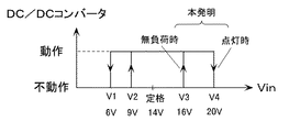
車載用の放電灯点灯装置に求められる機能として、放電灯の点灯維持電圧はバッテリーのレギュレータ故障時などを考慮し、また、車の走行中における立ち消え状態を最小限にするために、電源電圧がある程度上昇しても点灯状態を維持するほうが良い。そのため、従来の制御方式では、点灯可能電圧の上限値(V3)を、電源監視部による点灯維持電圧(V4)と同じ高い電圧(図6の20V程度)に設定していた。
【0005】
すなわち、DC/DCコンバータ1の入力電圧Vinは電源監視部4により検出され、抵抗R1,R2により分圧されて、コンパレータCMPにより基準電圧Vrefと比較される。コンパレータCMPの出力は抵抗R4によりプルアップされており、コンパレータCMPの出力によりリセット回路5を動作させて、DC/DCコンバータ1を制御するためのPWM回路6の動作を停止させるようになっている。
【0006】
【発明が解決しようとする課題】
従来例では、電源監視部4による点灯維持電圧(V4)を始動開始電圧(V3)とほぼ同じに設定しているため、高い電源電圧時に、起動時の無負荷状態となるため、DC/DCコンバータ1を構成する回路の半導体素子などに比較的大きな電圧ストレスが印加される。そのため、耐圧の高い素子が必要になり、素子の大型化、コストアップにつながっていた。また、電源監視部のみで、始動開始電圧(V3)と点灯維持電圧(V4)とにヒステリシスをつけて点灯可能電圧の上限を下げてもバッテリ電圧(電源電圧)がスローアップする場合には、有効なヒステリシスの範囲が狭くなる欠点があった。
【0007】
本発明は上述のような点に鑑みてなされたものであり、その目的とするところは、高い電源電圧入力時に無負荷状態になることはなく、半導体素子に印加される電圧ストレスを低減できる車載用の放電灯点灯装置を提供することにある。
【0008】
【課題を解決するための手段】
本発明の放電灯点灯装置にあっては、上記の課題を解決するために、図1及び図2に示すように、直流電源Eと、直流電源Eを昇圧して負荷への供給電力を制御する直流昇圧回路1と、直流昇圧回路1から出力される直流電圧を交流電圧に変換するインバータ回路2と、インバータ回路2から出力される交流電圧を供給される放電灯Laと、放電灯Laの起動時に高圧パルスを印加する起動回路3と、放電灯Laの無負荷状態/点灯状態を判別するために直流昇圧回路1の出力電圧を検出する出力電圧検出部7と、出力電圧検出部7により検出された信号と点灯判別しきい値を比較して点灯判別信号を出力する点灯判別回路8と、直流昇圧回路1に入力される電源電圧を検出する入力電圧検出部4と、直流昇圧回路1を制御・駆動する制御部6と、点灯判別回路8から出力される点灯判別信号に応じた可変しきい値と入力電圧検出部4の検出信号を比較して異常に高い電源電圧の入力時には点灯時であっても無負荷時であっても制御部6の動作を停止させる電圧比較部(コンパレータCMP)とを備え、図2に示すように、無負荷時の直流昇圧回路1の動作可能な電源電圧(V3)よりも点灯時の直流昇圧回路1の動作可能な電源電圧(V4)を高く設定したことを特徴とするものである。
【0009】
このように、本発明によれば、起動時の無負荷状態では、点灯可能電圧上限(V3)を点灯維持電圧上限(V4)より低くし、起動後、放電が安定して2次電圧が低下したら点灯維持電圧上限(V4)まで動作可能にするように電源監視回路のしきい値を切り替える。また、放電灯Laが消灯したら、高い電源電圧時に起動して過度な電圧ストレスを発生させないように、起動可能な電源電圧のしきい値を点灯可能電圧上限(V3)に切り替える。
【0010】
上記の構成を採ることにより、高い電源電圧入力時に、無負荷状態になることはなく、従って、直流昇圧回路1の半導体素子に印加される電圧ストレスを低減でき、使用する半導体素子の小型化、低コスト化が実現できる。従って、装置の小型化、低コスト化に大きく寄与するものである。
【0011】
【発明の実施の形態】
(実施例1)
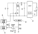
図1に実施例1の回路構成を示す。図中、Eは直流電源、1は直流電源Eを昇圧して負荷である放電灯への供給電力を制御する直流昇圧回路(DC/DCコンバータ)、2は直流電圧を交流電圧に変換するインバータ回路、3は負荷である放電灯の起動時に高圧パルスを印加する起動回路(イグナイタ)、Laは負荷としての放電灯である。
【0012】
DC/DCコンバータ1は、スイッチング素子QとトランスT、ダイオードD及びコンデンサCを含み、スイッチング素子Qを高周波でオン・オフすることにより、トランスTの1次側に直流電源Eを断続的に接続し、トランスTの2次側に昇圧された高周波電圧を得て、これをダイオードDにより整流して、コンデンサCに昇圧された直流電圧を得るものである。インバータ回路2は例えばフルブリッジ回路で構成され、入力直流電圧を低周波の矩形波交流電圧に変換して出力するものである。
【0013】
DC/DCコンバータ1の入力電圧Vinは電源電圧監視部4により入力電圧Vinとして検出されている。また、DC/DCコンバータ1の出力電圧はランプ電圧検出部7によりランプ電圧VLaとして検出されている。ランプ電圧検出部7により検出されたランプ電圧VLaに基づいて、点灯判別回路8により放電灯Laの無負荷状態/点灯状態を判別している。入力電圧Vinは、抵抗R1,R2,R3により分圧されて、コンパレータCMPにより基準電圧Vrefと比較される。分圧用の抵抗R3にはスイッチ素子Sが並列接続されており、点灯判別回路8の点灯判別信号によりスイッチ素子Sのオン/オフが制御される。これにより、コンパレータCMPは可変しきい値の電圧比較器となる。コンパレータCMPの出力は抵抗R4によりプルアップされており、コンパレータCMPの出力によりリセット回路5を動作させて、DC/DCコンバータ1のPWM回路6の動作を停止させるようになっている。PWM回路6はDC/DCコンバータ1のスイッチング素子Qのオン・オフ動作を制御しており、PWM回路6の動作が停止すると、DC/DCコンバータ1の動作も停止する。
【0014】
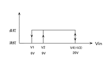
図2は本実施例の動作説明図である。同図に示すように、無負荷時(消灯時)には、DC/DCコンバータ1の動作可能な電源電圧VinをV3(DC12V系の場合、例えば、16V程度)とし、点灯時には、DC/DCコンバータ1の動作可能な電源電圧VinをV4(DC12V系の場合、例えば、20V程度)とすることにより、高い電源電圧入力時に、無負荷状態になることはなく、従って、DC/DCコンバータ1の半導体素子に印加される電圧ストレスを低減でき、使用する半導体素子の小型化、低コスト化が実現できる。したがって、点灯装置の小型化、低コスト化に大きく寄与するものである。
【0015】
さらに付け加えれば、点灯装置の定格入力電圧を100%とした場合、無負荷時の動作可能上限電圧V3を110〜120%程度、点灯時の動作可能上限電圧V4を130〜150%程度に設定することが望ましい。
【0016】
(実施例2)
図3に実施例2の回路構成を示す。図中、Eは直流電源、1は直流電源Eを昇圧して負荷である放電灯への供給電力を制御する直流昇圧回路(DC/DCコンバータ)、2は直流電圧を交流電圧に変換するインバータ回路、3は負荷である放電灯の起動時に高圧パルスを印加する起動回路(イグナイタ)、Laは負荷としての放電灯である。
【0017】
DC/DCコンバータ1は、スイッチング素子QとトランスT、ダイオードD及びコンデンサCを含み、スイッチング素子Qを高周波でオン・オフすることにより、トランスTの1次側に直流電源Eを断続的に接続し、トランスTの2次側に昇圧された高周波電圧を得て、これをダイオードDにより整流して、コンデンサCに昇圧された直流電圧を得るものである。インバータ回路2は例えばフルブリッジ回路で構成され、入力直流電圧を低周波の矩形波交流電圧に変換して出力するものである。
【0018】
DC/DCコンバータ1の入力電圧は電源電圧監視部4により入力電圧Vinとして検出されている。また、DC/DCコンバータ1の出力電流(インバータ回路の入力電流)はランプ電流検出部9によりランプ電流ILaとして検出されている。ランプ電流検出部9により検出されたランプ電流ILaに基づいて、点灯判別回路8により放電灯Laの無負荷状態/点灯状態を判別している。入力電圧Vinは、抵抗R1,R2,R3により分圧されて、コンパレータCMPにより基準電圧Vrefと比較される。分圧用の抵抗R3にはMOSFETよりなるスイッチ素子Sが並列接続されており、点灯判別回路8の点灯判別信号によりスイッチ素子Sのオン/オフが制御される。これにより、コンパレータCMPは可変しきい値の電圧比較器となる。コンパレータCMPの出力は抵抗R4によりプルアップされており、コンパレータCMPの出力によりリセット回路5を動作させて、DC/DCコンバータ1のPWM回路6の動作を停止させるようになっている。PWM回路6はDC/DCコンバータ1のスイッチング素子Qのオン・オフ動作を制御しており、PWM回路6の動作が停止すると、DC/DCコンバータ1の動作も停止する。
【0019】
図2は本実施例の動作説明図である。同図に示すように、無負荷時(消灯時)には、DC/DCコンバータ1の動作可能な電源電圧VinをV3(DC12V系の場合、例えば、16V程度)とし、点灯時には、DC/DCコンバータ1の動作可能な電源電圧VinをV4(DC12V系の場合、例えば、20V程度)とすることにより、高い電源電圧入力時に、無負荷状態になることはなく、従って、DC/DCコンバータ1の半導体素子に印加される電圧ストレスを低減でき、使用する半導体素子の小型化、低コスト化が実現できる。したがって、点灯装置の小型化、低コスト化に大きく寄与するものである。
【0020】
さらに付け加えれば、点灯装置の定格入力電圧を100%とした場合、無負荷時の動作可能上限電圧V3を110〜120%程度、点灯時の動作可能上限電圧V4を130〜150%程度に設定することが望ましい。
【0021】
(実施例3)
図4に実施例3の回路構成を示す。図中、Eは直流電源、1は直流電源Eを昇圧して負荷である放電灯への供給電力を制御する直流昇圧回路(DC/DCコンバータ)、2は直流電圧を交流電圧に変換するインバータ回路、3は負荷である放電灯の起動時に高圧パルスを印加する起動回路(イグナイタ)、Laは負荷としての放電灯である。
【0022】
DC/DCコンバータ1は、スイッチング素子QとトランスT、ダイオードD1,D2、インダクタL1及びコンデンサCを含み、スイッチング素子Qを高周波でオン・オフすることにより、トランスTの1次側に直流電源Eを断続的に接続し、トランスTの2次側に昇圧された高周波電圧を得て、これをダイオードD1により整流して、コンデンサCに昇圧された直流電圧を得るものである。ダイオードD1のオフ時には、インダクタL1の蓄積エネルギが回生用のダイオードD2を介してコンデンサCに充電される。
【0023】
インバータ回路2はスイッチング素子Q1〜Q4で構成されたフルブリッジ回路よりなる。スイッチング素子Q1〜Q4はインバータ駆動回路10により制御・駆動されており、スイッチング素子Q1,Q4がオン、スイッチング素子Q2,Q3がオフの状態と、スイッチング素子Q1,Q4がオフ、スイッチング素子Q2,Q3がオンの状態とが交番することにより、入力直流電圧を低周波の矩形波交流電圧に変換して出力するものである。
【0024】
DC/DCコンバータ1の入力電圧は電源電圧監視部4により入力電圧Vinとして検出されている。また、DC/DCコンバータ1の出力電流(インバータ回路2の入力電流)はランプ電流検出部9によりランプ電流ILaとして検出されている。ランプ電流検出部9により検出されたランプ電流ILaに基づいて、点灯判別回路8により放電灯Laの無負荷状態/点灯状態を判別している。入力電圧Vinは、抵抗R1,R2により分圧されて、コンパレータCMPにより可変基準電圧Vkと比較される。可変基準電圧Vkは、点灯判別回路8の点灯判別信号により放電灯Laの無負荷状態と点灯状態とで異なる電圧に切り替えられる。これにより、コンパレータCMPは可変しきい値の電圧比較器となる。コンパレータCMPの出力は抵抗R4によりプルアップされており、コンパレータCMPの出力によりリセット回路5を動作させて、DC/DCコンバータ1のPWM回路6の動作を停止させるようになっている。PWM回路6はDC/DCコンバータ1のスイッチング素子Qのオン・オフ動作を制御しており、PWM回路6の動作が停止すると、DC/DCコンバータ1の動作も停止する。さらに、本実施例では、リセット回路5の出力により、インバータ駆動回路10の動作も停止させており、これにより、インバータ回路2のスイッチング素子Q1〜Q4も動作を停止する。
【0025】
図2は本実施例の動作説明図である。同図に示すように、無負荷時(消灯時)には、DC/DCコンバータ1の動作可能な電源電圧VinをV3(DC12V系の場合、例えば、16V程度)とし、点灯時には、DC/DCコンバータの動作可能な電源電圧VinをV4(DC12V系の場合、例えば、20V程度)とすることにより、高い電源電圧入力時に、無負荷状態になることはなく、従って、DC/DCコンバータ1の半導体素子に印加される電圧ストレスを低減でき、使用する半導体素子の小型化、低コスト化が実現できる。したがって、点灯装置の小型化、低コスト化に大きく寄与するものである。
【0026】
さらに付け加えれば、点灯装置の定格入力電圧を100%とした場合、無負荷時の動作可能上限電圧V3を110〜120%程度、点灯時の動作可能上限電圧V4を130〜150%程度に設定することが望ましい。
【0027】
【発明の効果】
本発明の放電灯点灯装置では、起動時の無負荷状態では点灯可能電圧上限を低く設定し、起動後に放電が安定して直流昇圧回路の2次電圧が低下したら高い電源電圧まで動作可能とするように電源監視用のしきい値を切り替えているので、バッテリーのレギュレータが故障して走行中に電源電圧が上昇した場合でも、点灯状態を維持することができ、車載用の照明装置としての安全性を高めることができるという効果がある。また、放電灯が消灯したら、起動可能な電源電圧のしきい値を下げることにより、高い電源電圧時に起動して過度な電圧ストレスを発生させることはなく、従って、素子に印加される電圧ストレスを低減でき、使用する素子の小型化、低コスト化が実現でき、装置の小型化、低コスト化に大きく寄与するものである。
【図面の簡単な説明】
【図1】本発明の実施例1の回路図である。
【図2】本発明の実施例1〜3の動作説明図である。
【図3】本発明の実施例2の回路図である。
【図4】本発明の実施例3の回路図である。
【図5】従来例の回路図である。
【図6】従来例の動作説明図である。
【符号の説明】
1 DC−DCコンバータ(直流昇圧回路)
2 インバータ
3 イグナイタ
4 入力電圧検出回路
5 リセット回路
6 PWM回路
7 出力電圧検出回路
8 点灯判別回路[0001]
BACKGROUND OF THE INVENTION
The present invention relates to an in-vehicle discharge lamp lighting device.
[0002]
[Prior art]
FIG. 5 shows a configuration example of a conventional in-vehicle discharge lamp lighting device. In the figure, E is a DC power source, 1 is a DC booster circuit (hereinafter referred to as a DC / DC converter) that boosts the DC power source and controls the power supplied to a discharge lamp as a load, and 2 converts a DC voltage to AC. An
[0003]
In the conventional in-vehicle discharge lamp lighting device, when the discharge lamp La as a load is started, the DC /
[0004]
As a function required for in-vehicle discharge lamp lighting devices, the discharge lamp lighting maintenance voltage is taken into consideration when the regulator of the battery is broken, etc. It is better to keep the lighting state even if it rises to some extent. Therefore, in the conventional control method, the upper limit value (V3) of the lighting possible voltage is set to the same high voltage (about 20 V in FIG. 6) as the lighting maintenance voltage (V4) by the power supply monitoring unit.
[0005]
That is, the input voltage Vin of the DC /
[0006]
[Problems to be solved by the invention]
In the conventional example, since the lighting maintenance voltage (V4) by the power
[0007]
The present invention has been made in view of the above points, and an object of the present invention is to provide an in-vehicle device that can reduce voltage stress applied to a semiconductor element without being in a no-load state when a high power supply voltage is input. Disclosed is a discharge lamp lighting device.
[0008]
[Means for Solving the Problems]
In the discharge lamp lighting device of the present invention, in order to solve the above-described problem, as shown in FIGS. 1 and 2, the DC power source E and the DC power source E are boosted to control the power supplied to the load. A
[0009]
Thus, according to the present invention, in the no-load state at the time of start-up, the lighting possible voltage upper limit (V3) is made lower than the lighting sustaining voltage upper limit (V4), and after starting, the discharge is stabilized and the secondary voltage is lowered. Then, the threshold value of the power supply monitoring circuit is switched so that the operation can be performed up to the lighting maintenance voltage upper limit (V4). Further, when the discharge lamp La is turned off, the threshold value of the startable power supply voltage is switched to the turn-on voltage upper limit (V3) so that the discharge lamp La starts at a high power supply voltage and does not generate excessive voltage stress.
[0010]
By adopting the above configuration, no high load voltage is applied when a high power supply voltage is input. Therefore, voltage stress applied to the semiconductor element of the
[0011]
DETAILED DESCRIPTION OF THE INVENTION
Example 1
FIG. 1 shows a circuit configuration of the first embodiment. In the figure, E is a DC power supply, 1 is a DC booster circuit (DC / DC converter) that boosts the DC power supply E and controls the power supplied to a discharge lamp as a load, and 2 is an inverter that converts DC voltage into AC voltage. A
[0012]
The DC /
[0013]
The input voltage Vin of the DC /
[0014]
FIG. 2 is a diagram for explaining the operation of this embodiment. As shown in the figure, when there is no load (when the light is extinguished), the power supply voltage Vin at which the DC /
[0015]
In addition, assuming that the rated input voltage of the lighting device is 100%, the operable upper limit voltage V3 at no load is set to about 110 to 120%, and the operable upper limit voltage V4 at lighting is set to about 130 to 150%. It is desirable.
[0016]
(Example 2)
FIG. 3 shows a circuit configuration of the second embodiment. In the figure, E is a DC power supply, 1 is a DC booster circuit (DC / DC converter) that boosts the DC power supply E and controls the power supplied to a discharge lamp as a load, and 2 is an inverter that converts DC voltage into AC voltage. A
[0017]
The DC /
[0018]
The input voltage of the DC /
[0019]
FIG. 2 is a diagram for explaining the operation of this embodiment. As shown in the figure, when there is no load (when the light is extinguished), the power supply voltage Vin at which the DC /
[0020]
In addition, assuming that the rated input voltage of the lighting device is 100%, the operable upper limit voltage V3 at no load is set to about 110 to 120%, and the operable upper limit voltage V4 at lighting is set to about 130 to 150%. It is desirable.
[0021]
Example 3
FIG. 4 shows a circuit configuration of the third embodiment. In the figure, E is a DC power supply, 1 is a DC booster circuit (DC / DC converter) that boosts the DC power supply E and controls the power supplied to a discharge lamp as a load, and 2 is an inverter that converts DC voltage into AC voltage. A
[0022]
The DC /
[0023]
The
[0024]
The input voltage of the DC /
[0025]
FIG. 2 is a diagram for explaining the operation of this embodiment. As shown in the figure, when there is no load (when the light is extinguished), the power supply voltage Vin at which the DC /
[0026]
In addition, assuming that the rated input voltage of the lighting device is 100%, the operable upper limit voltage V3 at no load is set to about 110 to 120%, and the operable upper limit voltage V4 at lighting is set to about 130 to 150%. It is desirable.
[0027]
【The invention's effect】
In the discharge lamp lighting device according to the present invention, the upper limit of the lighting possible voltage is set low in the no-load state at the time of start-up, and the discharge can be stabilized after start-up and the operation can be performed up to the high power supply voltage when the secondary voltage of the DC booster circuit decreases. Since the power supply monitoring threshold is switched, the lighting state can be maintained even when the battery regulator fails and the power supply voltage rises while driving, making it safe as an in-vehicle lighting device. There is an effect that can improve the nature. In addition, when the discharge lamp is extinguished, by lowering the threshold value of the power supply voltage that can be started up, it does not start up at a high power supply voltage and cause excessive voltage stress. Therefore, the voltage stress applied to the element is reduced. It is possible to reduce the size and cost of the elements to be used, which greatly contributes to the downsizing and cost reduction of the device.
[Brief description of the drawings]
FIG. 1 is a circuit diagram of
FIG. 2 is an operation explanatory diagram of
FIG. 3 is a circuit diagram of
FIG. 4 is a circuit diagram of
FIG. 5 is a circuit diagram of a conventional example.
FIG. 6 is an operation explanatory diagram of a conventional example.
[Explanation of symbols]
1 DC-DC converter (DC booster circuit)
2
Claims (3)
直流電源を昇圧して負荷への供給電力を制御する直流昇圧回路と、
直流昇圧回路から出力される直流電圧を交流電圧に変換するインバータ回路と、
インバータ回路から出力される交流電圧を供給される放電灯と、
放電灯の起動時に高圧パルスを印加する起動回路と、
放電灯の無負荷状態/点灯状態を判別するために直流昇圧回路の出力電圧を検出する出力電圧検出部と、
出力電圧検出部により検出された信号と点灯判別しきい値を比較して点灯判別信号を出力する点灯判別回路と、
直流昇圧回路に入力される電源電圧を検出する入力電圧検出部と、
直流昇圧回路を制御・駆動する制御部と、
点灯判別回路から出力される点灯判別信号に応じた可変しきい値と入力電圧検出部の検出信号を比較して異常に高い電源電圧の入力時には点灯時であっても無負荷時であっても制御部の動作を停止させる電圧比較部とを備え、
無負荷時の直流昇圧回路の動作可能な電源電圧よりも点灯時の直流昇圧回路の動作可能な電源電圧を高く設定したことを特徴とする放電灯点灯装置。DC power supply,
A DC booster circuit that boosts the DC power supply and controls the power supplied to the load;
An inverter circuit for converting a DC voltage output from the DC booster circuit into an AC voltage;
A discharge lamp supplied with AC voltage output from the inverter circuit;
A starting circuit for applying a high-pressure pulse when starting the discharge lamp;
An output voltage detector for detecting the output voltage of the DC booster circuit to determine the no-load state / lighting state of the discharge lamp;
A lighting discrimination circuit that compares the signal detected by the output voltage detector with a lighting discrimination threshold and outputs a lighting discrimination signal;
An input voltage detector for detecting a power supply voltage input to the DC booster circuit;
A control unit for controlling and driving the DC booster circuit;
The variable threshold value corresponding to the lighting determination signal output from the lighting determination circuit is compared with the detection signal of the input voltage detection unit. When an abnormally high power supply voltage is input , whether the light is on or no load is applied A voltage comparison unit for stopping the operation of the control unit,
A discharge lamp lighting device characterized in that a power supply voltage operable for a DC booster circuit during lighting is set higher than a power supply voltage operable for a DC booster circuit during no load.
直流電源を昇圧して負荷への供給電力を制御する直流昇圧回路と、
直流昇圧回路から出力される直流電圧を交流電圧に変換するインバータ回路と、
インバータ回路から出力される交流電圧を供給される放電灯と、
放電灯の起動時に高圧パルスを印加する起動回路と、
放電灯の無負荷状態/点灯状態を判別するために直流昇圧回路の出力電流を検出する出力電流検出部と、
出力電流検出部により検出された信号と点灯判別しきい値を比較して点灯判別信号を出力する点灯判別回路と、
直流昇圧回路に入力される電源電圧を検出する入力電圧検出部と、
直流昇圧回路を制御・駆動する制御部と、
点灯判別回路から出力される点灯判別信号に応じた可変しきい値と入力電圧検出部の検出信号を比較して異常に高い電源電圧の入力時には点灯時であっても無負荷時であっても制御部の動作を停止させる電圧比較部とを備え、
無負荷時の直流昇圧回路の動作可能な電源電圧よりも点灯時の直流昇圧回路の動作可能な電源電圧を高く設定したことを特徴とする放電灯点灯装置。DC power supply,
A DC booster circuit that boosts the DC power supply and controls the power supplied to the load;
An inverter circuit for converting a DC voltage output from the DC booster circuit into an AC voltage;
A discharge lamp supplied with AC voltage output from the inverter circuit;
A starting circuit for applying a high-pressure pulse when starting the discharge lamp;
An output current detector for detecting the output current of the DC booster circuit to determine the no-load state / lighting state of the discharge lamp;
A lighting determination circuit that compares the signal detected by the output current detection unit with a lighting determination threshold value and outputs a lighting determination signal;
An input voltage detector for detecting a power supply voltage input to the DC booster circuit;
A control unit for controlling and driving the DC booster circuit;
The variable threshold value corresponding to the lighting determination signal output from the lighting determination circuit is compared with the detection signal of the input voltage detection unit. When an abnormally high power supply voltage is input , whether the light is on or no load is applied A voltage comparison unit for stopping the operation of the control unit,
A discharge lamp lighting device characterized in that a power supply voltage operable for a DC booster circuit during lighting is set higher than a power supply voltage operable for a DC booster circuit during no load.
Priority Applications (1)
| Application Number | Priority Date | Filing Date | Title |
|---|---|---|---|
| JP01766399A JP3817948B2 (en) | 1999-01-26 | 1999-01-26 | Discharge lamp lighting device |
Applications Claiming Priority (1)
| Application Number | Priority Date | Filing Date | Title |
|---|---|---|---|
| JP01766399A JP3817948B2 (en) | 1999-01-26 | 1999-01-26 | Discharge lamp lighting device |
Publications (2)
| Publication Number | Publication Date |
|---|---|
| JP2000215996A JP2000215996A (en) | 2000-08-04 |
| JP3817948B2 true JP3817948B2 (en) | 2006-09-06 |
Family
ID=11950104
Family Applications (1)
| Application Number | Title | Priority Date | Filing Date |
|---|---|---|---|
| JP01766399A Expired - Lifetime JP3817948B2 (en) | 1999-01-26 | 1999-01-26 | Discharge lamp lighting device |
Country Status (1)
| Country | Link |
|---|---|
| JP (1) | JP3817948B2 (en) |
Families Citing this family (6)
| Publication number | Priority date | Publication date | Assignee | Title |
|---|---|---|---|---|
| DE10290425B4 (en) * | 2001-01-12 | 2011-01-05 | Panasonic Electric Works Co., Ltd., Kadoma-shi | Ballast for a discharge lamp |
| DE10353835A1 (en) | 2003-11-18 | 2005-06-16 | Robert Bosch Gmbh | Method for operating a boost converter |
| US7057356B2 (en) * | 2004-11-10 | 2006-06-06 | Osram Sylvania Inc. | High intensity discharge lamp with boost circuit |
| JP5058778B2 (en) * | 2007-12-25 | 2012-10-24 | パナソニック株式会社 | Light source lighting device, lighting fixture, lighting system |
| JP4840382B2 (en) * | 2008-03-10 | 2011-12-21 | パナソニック電工株式会社 | Discharge lamp lighting device |
| JP5442172B2 (en) * | 2011-11-21 | 2014-03-12 | 三菱電機株式会社 | Light source lighting device |
-
1999
- 1999-01-26 JP JP01766399A patent/JP3817948B2/en not_active Expired - Lifetime
Also Published As
| Publication number | Publication date |
|---|---|
| JP2000215996A (en) | 2000-08-04 |
Similar Documents
| Publication | Publication Date | Title |
|---|---|---|
| US6861812B2 (en) | Discharge lamp ballast with DC-DC converter | |
| WO2007069481A1 (en) | Discharge lamp ignition device | |
| JP2009522727A (en) | Ripple reduction method for electronic ballast | |
| US6744222B2 (en) | Discharge lamp lighting apparatus and lamp apparatus | |
| EP1542513B1 (en) | High-voltage discharge lamp operating device | |
| JP3817948B2 (en) | Discharge lamp lighting device | |
| JP3480120B2 (en) | Discharge lamp lighting device | |
| JPH10199692A (en) | Lighting equipment for discharge lamp and lighting equipment in discharge lamp | |
| JP3829428B2 (en) | Discharge lamp lighting device | |
| JPH04342993A (en) | Discharge lamp lighting device | |
| JPH11262256A (en) | Power unit and electric discharge lamp turning-on device | |
| WO2002028150A1 (en) | Circuit for lighting hid lamp | |
| JPH11176583A (en) | High tension discharge lamp glowing device | |
| JPH0945490A (en) | Lighting device for discharge lamp | |
| JP4721937B2 (en) | Discharge lamp lighting device | |
| JP2000243584A (en) | Discharge lamp lighting device | |
| JPH0955296A (en) | Discharge lamp lighting device | |
| JPH07192881A (en) | High-frequency power source device, discharge lamp lighting device and luminaire | |
| JPH07272880A (en) | Discharge lamp lighting device | |
| JPH0518878Y2 (en) | ||
| JP4206637B2 (en) | Discharge lamp lighting device | |
| JP4590718B2 (en) | High pressure discharge lamp lighting device | |
| JP6045858B2 (en) | Discharge lamp lighting device | |
| JP2002051548A (en) | Power supply and discharge lamp lighting device | |
| JP3121383B2 (en) | Discharge lamp lighting device |
Legal Events
| Date | Code | Title | Description |
|---|---|---|---|
| A977 | Report on retrieval |
Free format text: JAPANESE INTERMEDIATE CODE: A971007 Effective date: 20050425 |
|
| A131 | Notification of reasons for refusal |
Free format text: JAPANESE INTERMEDIATE CODE: A131 Effective date: 20050510 |
|
| A521 | Written amendment |
Free format text: JAPANESE INTERMEDIATE CODE: A523 Effective date: 20050708 |
|
| TRDD | Decision of grant or rejection written | ||
| A01 | Written decision to grant a patent or to grant a registration (utility model) |
Free format text: JAPANESE INTERMEDIATE CODE: A01 Effective date: 20060523 |
|
| A61 | First payment of annual fees (during grant procedure) |
Free format text: JAPANESE INTERMEDIATE CODE: A61 Effective date: 20060605 |
|
| R150 | Certificate of patent or registration of utility model |
Free format text: JAPANESE INTERMEDIATE CODE: R150 |
|
| FPAY | Renewal fee payment (event date is renewal date of database) |
Free format text: PAYMENT UNTIL: 20090623 Year of fee payment: 3 |
|
| S533 | Written request for registration of change of name |
Free format text: JAPANESE INTERMEDIATE CODE: R313533 |
|
| FPAY | Renewal fee payment (event date is renewal date of database) |
Free format text: PAYMENT UNTIL: 20090623 Year of fee payment: 3 |
|
| R350 | Written notification of registration of transfer |
Free format text: JAPANESE INTERMEDIATE CODE: R350 |
|
| FPAY | Renewal fee payment (event date is renewal date of database) |
Free format text: PAYMENT UNTIL: 20100623 Year of fee payment: 4 |
|
| FPAY | Renewal fee payment (event date is renewal date of database) |
Free format text: PAYMENT UNTIL: 20100623 Year of fee payment: 4 |
|
| FPAY | Renewal fee payment (event date is renewal date of database) |
Free format text: PAYMENT UNTIL: 20110623 Year of fee payment: 5 |
|
| FPAY | Renewal fee payment (event date is renewal date of database) |
Free format text: PAYMENT UNTIL: 20120623 Year of fee payment: 6 |
|
| FPAY | Renewal fee payment (event date is renewal date of database) |
Free format text: PAYMENT UNTIL: 20120623 Year of fee payment: 6 |
|
| FPAY | Renewal fee payment (event date is renewal date of database) |
Free format text: PAYMENT UNTIL: 20130623 Year of fee payment: 7 |
|
| EXPY | Cancellation because of completion of term |


