JP3766862B2 - Automotive seat backrest frame - Google Patents
Automotive seat backrest frame Download PDFInfo
- Publication number
- JP3766862B2 JP3766862B2 JP07907999A JP7907999A JP3766862B2 JP 3766862 B2 JP3766862 B2 JP 3766862B2 JP 07907999 A JP07907999 A JP 07907999A JP 7907999 A JP7907999 A JP 7907999A JP 3766862 B2 JP3766862 B2 JP 3766862B2
- Authority
- JP
- Japan
- Prior art keywords
- pair
- backrest frame
- portions
- reclining device
- upper portion
- Prior art date
- Legal status (The legal status is an assumption and is not a legal conclusion. Google has not performed a legal analysis and makes no representation as to the accuracy of the status listed.)
- Expired - Fee Related
Links
Images
Classifications
-
- B—PERFORMING OPERATIONS; TRANSPORTING
- B60—VEHICLES IN GENERAL
- B60N—SEATS SPECIALLY ADAPTED FOR VEHICLES; VEHICLE PASSENGER ACCOMMODATION NOT OTHERWISE PROVIDED FOR
- B60N2/00—Seats specially adapted for vehicles; Arrangement or mounting of seats in vehicles
- B60N2/68—Seat frames
- B60N2/682—Joining means
Landscapes
- Engineering & Computer Science (AREA)
- Aviation & Aerospace Engineering (AREA)
- Transportation (AREA)
- Mechanical Engineering (AREA)
- Chair Legs, Seat Parts, And Backrests (AREA)
- Seats For Vehicles (AREA)
Description
【0001】
【発明の属する技術分野】
この発明は、両サイドがリクライニング装置で支持される自動車用シートのバックレストフレームに関する。
【0002】
【従来の技術】
通常、シートバックは着座乗員の上半身背部から入力を受けている。急発進時や他の車によって追突を受けたとき、通常時より大きい負荷を受けるが、シートバックの内部にあってこの負荷を担っているのがバックレストフレームである。このバックレストフレームはシートスライドのアッパーレールに支持されるか、クッションフレームを介して間接的にシートスライドのアッパーレールに支持されている。
【0003】
着座者の角度調整のため、シートバックとシートスライドの間にリクライニング装置が取り付けられるか、またはシートバックとシートクッションフレームの間にリクライニング装置が取り付けられ、さらにシートクッションフレームがシートスライドに取り付けられる二つの方法が一般的に採用されている。リクライニング装置の取付方法として、リクライニング装置が片側に付いている片側ロックのものと、両側に付いている両側ロックのものとがある。
【0004】
図15に示すように、片側ロック用のバックレストフレームは、パイプ33を全周に張り巡らした構造とし、これにリクライニング装置の取付ブラケット34などを溶接して構成されている。
図16に示すように、両側ロック用のバックレストフレームは、主に前後モーメント入力のため、アッパー側のパイプ33、サイド側のリクライニング装置の取付ブラケット34およびロア側の連結部35からなる4分割フレームから構成されている。
【0005】
このように、片側または両側ロック用のバックレストフレームは、強度部材としてのパイプ33とリクライニング装置やSばねの取付部を兼ねた取付ブラケット34とから構成していた。さらにヘッドレストグロメットを支持するヘッドレストホルダ37やカバーの端末処理として使用されるワイヤ36など適宜付属部品が不可欠であった。これらの部品はいずれもあらかじめ製作し、溶接治具にセットし、溶接で一体に構成していた。
【0006】
【発明が解決しようとする課題】
しかし、このような従来の自動車用シートのバックレストフレームでは、強度部材としてのパイプ、取付ブラケットをメインメンバとし、ヘッドレストホルダやワイヤなどをサブメンバとする構造であるので、溶接箇所および部品点数が増大し、組立が面倒で、組立性が悪いという問題があった。
そこで、この発明は、前記問題点に着目してなされたもので、その目的は、溶接箇所および部品点数を減少させ、組立性を向上させることのできる自動車用シートのバックレストフレームを提供することにある。
【0007】
【課題を解決するための手段】
前記目的を達成するために、請求項1記載の発明では、両サイドがリクライニング装置によって支持される自動車用シートのバックレストフレームであって、前記リクライニング装置によって支持される所定幅の左右一対のサイド部と、これら左右一対のサイド部の上部を連設する所定幅のアッパー部と、左右一対のサイド部の下部を連設するロア部と、これらの一対のサイド部、アッパー部およびロア部の一側の端縁から折り曲げによって連設された底板部と、少なくとも一対のサイド部およびアッパー部の他側の端縁から折り返された折り返し部と、前記左右一対の底板部間に連設された1以上の横断部と、前記アッパー部下側の底板部への切り起こしによりアッパー部に沿って形成されたヘッドレスト用のホルダ支持部と、このホルダ支持部およびアッパー部に形成されたヘッドレストステイの直接または間接の支持孔とを備え、全体が板金のプレス加工によって形成され、前記左右一対のサイド部のリクライニング装置取付位置に補強手段を設けたことを特徴とする。この発明では、部品点数が減少し、組立工数が減少し、溶接箇所が少なく品質が安定する。また、付属部品取付のための加工工数が減少する。さらに、補強手段を介してリクライニング装置を取り付けるため、バックレストフレームは最適な板厚に設定することができる。
【0008】
また、ホルダ支持部は絞り加工で成形できる限界を超えているので、別途ホルダ用の部品の取り付けが必要が、この発明では、これを不要にすることができる。
【0009】
さらに、パッドを支持するばね類を不要にし、部品点数を減少させることができる。
【0010】
請求項2記載の発明は、前記1以上の横断部のうち、腰椎支持位置の横断部に前方へ盛り上げた盛上部を形成したことを特徴とする。この発明では、盛り上げ高さの変化で着座者の腰椎部支持圧を調整することができ、また、パッドの厚さを薄くできるので、パッドの使用量を減少させ、シートの軽量化を図ることができる。
【0011】
【発明の実施の形態】
(実施の形態1)
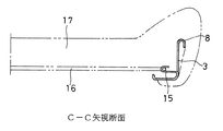
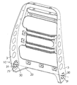
以下、本発明の実施の形態を図面に基づいて詳細に説明する。図1は実施の形態1に係る自動車用シートのバックレストフレームを示す斜視図、図2は図1のA−A矢視断面図、図3は図1の補強手段を示す斜視図、図4は図1のB−B矢視断面図、図5はヘッドレスト用グロメットを示す斜視図、図6は図1のC−C矢視断面図である。
【0012】
この実施の形態1は、シートスライドのアッパーレールに二つのリクライニング装置で両側から支持されるか又はクッションフレームに二つのリクライニング装置で両側から支持され、クッションフレームを介して間接的にシートスライドのアッパーレールに支持される自動車用シートのバックレストフレームに適用したものである。
【0013】
このように、両サイドがリクライニング装置によって支持される自動車用シートのバックレストフレームは、リクライニング装置によって支持される所定幅の左右一対のサイド部3、3と、これら左右一対のサイド部3、3の上部を連設する所定幅のアッパー部4と、一対のサイド部3、3の下部を連設するロア部5と、左右一対のサイド部3、3、アッパー部4およびロア部5の一側の端縁から折り曲げによって連設された底板部6と、一対のサイド部3、3、アッパー部4およびロア部5の他側の端縁から折り返された折り返し部8とを備え、全体が板金のプレス加工によって形成されている。
【0014】
上記ロア部5は、両側ロックにより、他の三周囲に比べ強度が要求されないので、細幅となっており、場合によっては折り返し部8を不要にすることができる。前記折り返し部8は、この実施の形態1では略逆U字状部であるが、これに代えて略逆U字状部の先端が開いた逆U字状、略逆U字状部の先端が閉じた逆U字状または略逆U字状をつぶした形状とすることもできる。
【0015】
前記左右一対のサイド部3、3のリクライニング装置取付位置に補強手段10が設けられ、この補強手段10は補強板11と、この補強板11に溶接される角ナット12とからなる。この実施の形態1では、角ナット12溶接済み補強板11が溶接により固着されているが、これに代えて2個のTナットあるいは2連のTナットを用い、これらのTナットのフランジ部を溶接することもできる。
【0016】
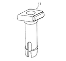
前記アッパー部4の下側に下方からの切り起こしによりアッパー部4に沿ったヘッドレスト用のホルダ支持部7が形成され、このホルダ支持部7およびアッパー部4に図5に示すヘッドレスト用グロメット13を支持するホルダを支持または貫通する左右一対の支持孔14が形成されている。
【0017】
前記サイド部3、3には、一部を切り起こして折り曲げることによりスプリングハンガ15が形成されている。図6に示すように、このスプリングハンガ15を介して左右一対のサイド部3、3間にSばねなどのスプリング16が複数本掛け渡され、パッド17を弾性的に支持する構造となっている。また、前記左右一対の底板部6、6間には、アッパー部4寄りの位置に横断部18が形成されている。
【0018】
次に、前記した自動車用シートのバックレストフレームの組立手順を説明する。このバックレストフレームの組み立てに際し、まず、あらかじめプレス加工により成形したバックレストフレームを用いる。次いで、左右一対のサイド部3、3のリクライニング装置取付位置に角ナット12溶接済み補強板11を溶接により固着する。これにより、バックレストフレームの組み立てを終了する。
【0019】
このように、この実施の形態1では、バックレストフレームが板金のプレス加工により形成される構造であるので、溶接箇所が減少し、品質が安定し、組立性が向上する。また、従来、不可欠であったメインメンバとしてのパイプやサブメンバとしてのワイヤなどを不要にできるので、部品点数を減少させることができる。
【0020】
また、この実施の形態1では、左右一対のサイド部3、3のリクライニング装置取付位置に補強手段10を設けたので、バックレストフレームの板厚を最適な値に設定し、薄くすることができる。
また、この実施の形態1では、前記ホルダ支持部は絞り加工で成形できる限界を超えているので、別途ホルダ用の部品の取り付けが必要である。この実施の形態1では、これを不要にすることができる。
さらに、この実施の形態1では、左右一対の底板部6、6間には、アッパー部4寄りの位置に横断部18を連設した構造としたので、パッドを支持するばね類を不要にし、部品点数を減少させることができる。また、ヘッドレストステイを後方に突出させず、後方から触れることができない。
【0021】
(実施の形態2)
図7は実施の形態2に係る自動車用シートのバックレストフレームを示す斜視図、図8は図7のD−D矢視断面図、図9は図7のE−E矢視断面図である。
この実施の形態2に係る自動車用シートのバックレストフレームは、前記実施の形態1と略同様の構成を有するが、左右一対の底板部6、6間には、横断部18に加えて、着座者の腰椎部に相当する中央位置に横断部19を形成し、この横断部19に中央部位を前方に盛り上げた盛上部21を形成し、この盛上部21でパット17の中央部を直接支持した構造としたものである。
この構造により、盛り上げ高さの変化で着座者の腰椎部支持圧を調整することができる。また、パッド17の厚さを薄くできるので、パッド17の使用量を減少させ、シートの軽量化を図ることができる。
【0022】
(実施の形態1に係る変形形態)
図10は変形形態1における補強手段を示す斜視図である。この補強手段10は、前記実施の形態1と略同様の構成を有するが、実施の形態1の補強手段を改良した点で特徴を有する。
すなわち、この補強手段10は、補強板11をプレス加工により形成する際、この補強板11に孔22を打ち抜き、孔22の内周面に雌ねじ23を刻設した構造としたものである。この構造により、実施の形態1における溶接工程を不要にし、補強手段10の取付性や取付精度を向上させることができる。
【0023】
図11は変形形態2における補強手段を示す斜視図である。この補強手段10は、前記変形形態1と略同様の構成を有するが、変形形態1の補強手段を改良した点で特徴を有する。
すなわち、この補強手段10は、孔加工により補強板11に孔22を形成し、この孔22の内周面に雌ねじ23を刻設した構造としたものである。この構造により、変形形態1におけるプレス加工を不要にし、加工工数を減少させることができる。
【0024】
図12は変形形態3における補強手段を示す斜視図である。この補強手段10は、前記変形形態1と略同様の構成を有するが、変形形態1の補強手段を改良した点で特徴を有する。
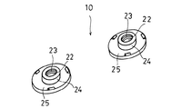
すなわち、この補強手段10は、2個のボス24付き補強円板25を用い、ボス24に孔22を形成し、この孔22の内周面に雌ねじ23を刻設した構造としたものである。この構造により、ボス24付き補強円板25を冷間鍛造により容易に製造でき、大きい強度を得ることができる。
【0025】
図13は変形形態4であって、円形リクライニング装置に適用した補強手段を示す斜視図、図14は円形リクライニング装置を示す斜視図である。この補強手段10は、前記変形形態1と略同様の構成を有するが、円形リクライニング装置26に適用した点で特徴を有する。
すなわち、図14に示すように、前記円形リクライニング装置26は、クッションフレーム側のベース27と、このベース27に対して回転角調整可能なバックレストフレーム側のアーム円板28とを備え、このアーム円板28からエンボス29が同心円状に多数突出しており、これらのエンボス29を介してバックレストフレームが支持される構造となっている。
【0026】
一方、図13に示すように、前記補強手段10は、補強円板25を用い、この補強円板25は中心に軸孔30を有し、この軸孔30の周囲にエンボス挿入孔31が多数等間隔で同心円状に形成されている。左右一対のサイド部3、3のリクライニング装置取付位置にはヒンジセンタ20に軸孔30が形成され、この軸孔30の周囲に補強円板25と同様のエンボス挿入孔31が多数等間隔で同心円状に形成され、このエンボス挿入孔31および軸孔30に補強円板25のエンボス挿入孔31および軸孔30を一致させた状態で補強円板25が溶接により固着されている。
【0027】
円形リクライニング装置26の取り付けに際しては、アーム円板28より突出するエンボス29をサイド部3、3および補強円板25のエンボス挿入孔3、31に挿入し、挿入後、溶接またはカシメにて固着し、これにより円形リクライニング装置26を取り付ける。このように、エンボス挿入孔31を同心円状に多数形成した補強円板25を補強手段10として用いたので、円形リクライニング装置26に対して容易に適用することができる。
【0028】
【発明の効果】
以上の説明から明らかなように、請求項1記載の発明によれば、バックレストフレームは、サイド部と、アッパー部と、ロア部と、折り返し部と、横断部と、ヘッドレスト用のホルダ支持部とを備え、全体が板金のプレス加工により形成された構造としたので、部品点数および組立工数が減少し、溶接箇所が少なく品質が安定する。また、サイド部のリクライニング装置取付位置に補強手段を設けた構造としたので、バックレストフレームは最適な板厚に設定することができる。
【0029】
また、ホルダ支持部は絞り加工で成形できる限界を超えているので、別途ホルダ用の部品の取り付けが必要が、この発明では、これを不要にすることができる。
【0030】
さらに、左右一対の底板部間に1以上の横断部を連設した構造としたので、ばね類を不要にし、部品点数を減少させることができる。
【0031】
請求項2記載の発明によれば、前記1以上の横断部のうち、腰椎支持位置の横断部に前方へ盛り上げた盛上部を形成した構成としたので、盛り上げ高さの変化で着座者の腰椎部支持圧を調整することができ、また、パッドを厚さを薄くできるので、パッドの使用量を減少させ、シートの軽量化を図ることができる。
【図面の簡単な説明】
【図1】実施の形態1に係る自動車用シートのバックレストフレームを示す斜視図である。
【図2】図1のA−A矢視断面図である。
【図3】図1の補強手段を示す斜視図である。
【図4】図1のB−B矢視断面図である。
【図5】ヘッドレスト用グロメットを示す斜視図である。
【図6】図1のC−C矢視断面図である。
【図7】実施の形態2に係る自動車用シートのバックレストフレームを示す斜視図である。
【図8】図7のD−D矢視断面図である。
【図9】図7のE−E矢視断面図である。
【図10】変形形態1における補強手段を示す斜視図である。
【図11】変形形態2における補強手段を示す斜視図である。
【図12】変形形態3における補強手段を示す斜視図である。
【図13】変形形態4であって、円形リクライニング装置に適用した補強手段を示す斜視図である。
【図14】円形リクライニング装置を示す斜視図である。
【図15】従来の片側ロックタイプの自動車用シートのバックレストフレームを示す斜視図である。
【図16】従来の両側ロックタイプの自動車用シートのバックレストフレームを示す斜視図である。
【符号の説明】
3 サイド部
4 アッパー部
5 ロア部
6 底板部
7 ホルダ支持部
8 折り返し部
10 補強手段
11 補強板
12 角ナット
13 ヘッドレスト用グロメット
14 支持孔
15 スプリングハンガ
16 スプリングワイヤ
17 パッド
18 横断部
19 横断部
20 ヒンジセンタ
21 盛上部
22 孔
23 雌ねじ
24 ボス
25 補強円板
26 円形リクライニング装置
27 ベース
28 アーム円板
29 エンボス
30 軸孔
31 エンボス挿入孔[0001]
BACKGROUND OF THE INVENTION
The present invention relates to a backrest frame for an automobile seat in which both sides are supported by a reclining device.
[0002]
[Prior art]
Usually, the seat back receives input from the upper back of the seated occupant. When the vehicle starts suddenly or receives a rear-end collision with another vehicle, it receives a larger load than usual, but the backrest frame is in the seat back and bears this load. The backrest frame is supported by the upper rail of the seat slide or indirectly supported by the upper rail of the seat slide via the cushion frame.
[0003]
To adjust the angle of the seated person, a reclining device is attached between the seat back and the seat slide, or a reclining device is attached between the seat back and the seat cushion frame, and the seat cushion frame is attached to the seat slide. Two methods are commonly adopted. As a method of attaching the reclining device, there are a one-sided lock with the reclining device attached to one side and a two-sided lock attached to both sides.
[0004]
As shown in FIG. 15, the backrest frame for one-side locking has a structure in which a
As shown in FIG. 16, the backrest frame for both-side locks is mainly divided into four parts including a
[0005]
As described above, the backrest frame for locking on one side or both sides is composed of the
[0006]
[Problems to be solved by the invention]
However, such a conventional backrest frame for an automobile seat has a structure in which a pipe as a strength member and a mounting bracket are used as a main member and a headrest holder, a wire, and the like are used as sub-members. However, there is a problem that the assembly is troublesome and the assemblability is poor.
Accordingly, the present invention has been made paying attention to the above-mentioned problems, and an object thereof is to provide a backrest frame for an automobile seat that can reduce the number of welding points and the number of parts and improve the assemblability. It is in.
[0007]
[Means for Solving the Problems]
In order to achieve the above object, according to the first aspect of the present invention, a pair of left and right sides having a predetermined width supported by the reclining device, wherein both sides are backrest frames of an automobile seat supported by the reclining device. An upper portion having a predetermined width connecting the upper portions of the pair of left and right side portions, a lower portion connecting the lower portions of the pair of left and right side portions, and a pair of the side portions, the upper portion and the lower portion. A bottom plate portion provided continuously by bending from one end edge, a folded portion returned from the other end edge of at least one pair of side portions and upper portion, and a pair of left and right bottom plate portions. One or more crossing portions, a holder support portion for a headrest formed along the upper portion by cutting and raising the bottom plate portion below the upper portion, and the holder And a direct or indirect support hole of the headrest stays formed sandwiching member and the upper part, the whole is formed by pressing a metal plate, provided with a reinforcing means in the reclining device mounting positions of the pair of right and left side portions It is characterized by. In this invention, the number of parts is reduced, the number of assembling steps is reduced, the number of welding points is reduced, and the quality is stabilized. In addition, the number of processing steps for attaching the accessory parts is reduced. Furthermore, since the reclining device is attached via the reinforcing means, the backrest frame can be set to an optimum plate thickness.
[0008]
In addition, since the holder support part exceeds the limit that can be formed by drawing, it is necessary to separately attach a part for the holder. In the present invention, this can be made unnecessary.
[0009]
Furthermore, the springs that support the pad are not required, and the number of parts can be reduced.
[0010]
The invention according to claim 2 is characterized in that, among the one or more crossing portions, a raised portion raised upward is formed at the crossing portion at the lumbar support position. According to the present invention, the lumbar support pressure of the seated person can be adjusted by changing the raised height, and the thickness of the pad can be reduced, so that the amount of pad used can be reduced and the weight of the seat can be reduced. Can do.
[0011]
DETAILED DESCRIPTION OF THE INVENTION
(Embodiment 1)
Hereinafter, embodiments of the present invention will be described in detail with reference to the drawings. 1 is a perspective view showing a backrest frame of an automobile seat according to Embodiment 1, FIG. 2 is a cross-sectional view taken along line AA in FIG. 1, and FIG. 3 is a perspective view showing reinforcing means in FIG. FIG. 5 is a perspective view showing a grommet for a headrest, and FIG. 6 is a cross-sectional view taken along the line CC in FIG.
[0012]
In the first embodiment, the seat slide upper rail is supported from both sides by two reclining devices, or the cushion frame is supported from both sides by two reclining devices, and indirectly through the cushion frame. This is applied to a backrest frame of an automobile seat supported by a rail.
[0013]
As described above, the backrest frame of the automobile seat whose both sides are supported by the reclining device includes a pair of left and
[0014]
Since the
[0015]
Reinforcing means 10 is provided at the reclining device mounting positions of the pair of left and
[0016]
A head support
[0017]
A
[0018]
Next, a procedure for assembling the backrest frame of the automobile seat described above will be described. In assembling the backrest frame, first, a backrest frame that has been previously formed by press working is used. Subsequently, the
[0019]
Thus, in this Embodiment 1, since the backrest frame has a structure formed by pressing a sheet metal, the number of welded portions is reduced, the quality is stabilized, and the assemblability is improved. In addition, since the pipe as the main member and the wire as the sub member, which have been indispensable conventionally, can be eliminated, the number of parts can be reduced.
[0020]
Moreover, in this Embodiment 1, since the reinforcement means 10 was provided in the reclining apparatus attachment position of the left-right paired
Moreover, in this Embodiment 1, since the said holder support part exceeds the limit which can be shape | molded by drawing, it is necessary to attach the part for holders separately. In the first embodiment, this can be eliminated.
Furthermore, in this Embodiment 1, since it was set as the structure which connected the crossing
[0021]
(Embodiment 2)
7 is a perspective view showing a backrest frame of the automobile seat according to the second embodiment, FIG. 8 is a cross-sectional view taken along the line DD in FIG. 7, and FIG. 9 is a cross-sectional view taken along the line EE in FIG. .
The backrest frame of the automobile seat according to the second embodiment has substantially the same configuration as that of the first embodiment, but a seating is provided between the pair of left and right
With this structure, the lumbar support pressure of the seated person can be adjusted by changing the raised height. Further, since the thickness of the
[0022]
(Modified form according to Embodiment 1)
FIG. 10 is a perspective view showing the reinforcing means in the first modification. The reinforcing means 10 has substantially the same configuration as that of the first embodiment, but is characterized in that the reinforcing means of the first embodiment is improved.
That is, the reinforcing
[0023]
FIG. 11 is a perspective view showing a reinforcing means in the second modification. This reinforcing means 10 has substantially the same configuration as that of the first modification, but is characterized in that the reinforcing means of the first modification is improved.
That is, the reinforcing
[0024]
FIG. 12 is a perspective view showing a reinforcing means in the third modification. This reinforcing means 10 has substantially the same configuration as that of the first modification, but is characterized in that the reinforcing means of the first modification is improved.
That is, the reinforcing
[0025]
FIG. 13 is a perspective view showing a reinforcing means applied to the circular reclining device according to the fourth modification, and FIG. 14 is a perspective view showing the circular reclining device. The reinforcing means 10 has substantially the same configuration as that of the first modification, but is characterized in that it is applied to the
That is, as shown in FIG. 14, the
[0026]
On the other hand, as shown in FIG. 13, the reinforcing means 10 uses a reinforcing
[0027]
When the
[0028]
【The invention's effect】
As is apparent from the above description, according to the invention described in claim 1, the backrest frame includes the side portion, the upper portion, the lower portion, the folded portion, the transverse portion, and the holder support portion for the headrest. And the entire structure is formed by pressing a sheet metal, so that the number of parts and the number of assembling steps are reduced, and the quality is stabilized with fewer welded parts. Further, since the reinforcing means is provided at the reclining device mounting position of the side portion, the backrest frame can be set to an optimum plate thickness.
[0029]
In addition, since the holder support part exceeds the limit that can be formed by drawing, it is necessary to separately attach a part for the holder. In the present invention, this can be made unnecessary.
[0030]
In addition, since one or more crossing portions are connected between the pair of left and right bottom plate portions, springs are unnecessary, and the number of parts can be reduced.
[0031]
According to the second aspect of the present invention, since the raised portion is formed on the transverse portion of the lumbar support position among the one or more transverse portions, the raised portion is formed forward. The part supporting pressure can be adjusted, and the thickness of the pad can be reduced, so that the amount of pad used can be reduced and the weight of the seat can be reduced.
[Brief description of the drawings]
FIG. 1 is a perspective view showing a backrest frame of an automobile seat according to Embodiment 1. FIG.
FIG. 2 is a cross-sectional view taken along the line AA in FIG.
FIG. 3 is a perspective view showing a reinforcing means of FIG. 1;
4 is a cross-sectional view taken along the line B-B in FIG. 1;
FIG. 5 is a perspective view showing a headrest grommet.
6 is a cross-sectional view taken along the line CC in FIG.
7 is a perspective view showing a backrest frame of an automobile seat according to Embodiment 2. FIG.
8 is a cross-sectional view taken along line DD in FIG.
9 is a cross-sectional view taken along the line EE of FIG.
FIG. 10 is a perspective view showing a reinforcing means in the first modification.
FIG. 11 is a perspective view showing a reinforcing means in the second modification.
FIG. 12 is a perspective view showing a reinforcing means in the third modification.
FIG. 13 is a perspective view showing a reinforcing means applied to the circular reclining device according to the fourth modification.
FIG. 14 is a perspective view showing a circular reclining device.
FIG. 15 is a perspective view showing a backrest frame of a conventional one-side lock type automobile seat.
FIG. 16 is a perspective view showing a backrest frame of a conventional both-side lock type automobile seat.
[Explanation of symbols]
3 Side part 4
Claims (2)
Priority Applications (1)
| Application Number | Priority Date | Filing Date | Title |
|---|---|---|---|
| JP07907999A JP3766862B2 (en) | 1999-03-24 | 1999-03-24 | Automotive seat backrest frame |
Applications Claiming Priority (1)
| Application Number | Priority Date | Filing Date | Title |
|---|---|---|---|
| JP07907999A JP3766862B2 (en) | 1999-03-24 | 1999-03-24 | Automotive seat backrest frame |
Publications (2)
| Publication Number | Publication Date |
|---|---|
| JP2000270961A JP2000270961A (en) | 2000-10-03 |
| JP3766862B2 true JP3766862B2 (en) | 2006-04-19 |
Family
ID=13679900
Family Applications (1)
| Application Number | Title | Priority Date | Filing Date |
|---|---|---|---|
| JP07907999A Expired - Fee Related JP3766862B2 (en) | 1999-03-24 | 1999-03-24 | Automotive seat backrest frame |
Country Status (1)
| Country | Link |
|---|---|
| JP (1) | JP3766862B2 (en) |
Families Citing this family (10)
| Publication number | Priority date | Publication date | Assignee | Title |
|---|---|---|---|---|
| US7066552B2 (en) * | 2003-03-31 | 2006-06-27 | Ts Tech Co., Ltd. | Seat back frame for vehicle seat |
| DE102005005485A1 (en) * | 2005-02-04 | 2006-08-10 | Faurecia Autositze Gmbh & Co. Kg | Rear seat frame for a rear seat part of a vehicle seat and method for its production |
| JP5244436B2 (en) * | 2008-03-31 | 2013-07-24 | 富士機工株式会社 | Electric seat slide device |
| WO2011060219A1 (en) | 2009-11-12 | 2011-05-19 | Johnson Controls Technology Company | One-piece seat back frame assembly and method of making same |
| WO2011103501A2 (en) | 2010-02-19 | 2011-08-25 | Johnson Controls Technology Company | One-piece seat back structure |
| KR101445627B1 (en) | 2010-08-19 | 2014-09-29 | 존슨 컨트롤스 테크놀러지 컴퍼니 | One piece rear back |
| EP2655129A4 (en) * | 2010-12-21 | 2014-07-16 | Johnson Controls Tech Co | One piece back frame for a vehicle seat |
| JP2014502583A (en) | 2011-01-14 | 2014-02-03 | ジョンソン コントロールズ テクノロジー カンパニー | One-part seat back frame and manufacturing method |
| JP5817733B2 (en) * | 2011-07-15 | 2015-11-18 | 東レ株式会社 | Frame structure for backrest and manufacturing method thereof |
| CN107234993A (en) * | 2017-06-27 | 2017-10-10 | 重庆宏立至信汽车部件制造有限公司 | A kind of butt-welding type automobile backrest side board |
-
1999
- 1999-03-24 JP JP07907999A patent/JP3766862B2/en not_active Expired - Fee Related
Also Published As
| Publication number | Publication date |
|---|---|
| JP2000270961A (en) | 2000-10-03 |
Similar Documents
| Publication | Publication Date | Title |
|---|---|---|
| EP0625445B1 (en) | Seat back frame | |
| JP3594162B2 (en) | Seat back frame | |
| JP3148336B2 (en) | Front seat cushion structure | |
| JP3766862B2 (en) | Automotive seat backrest frame | |
| JP3415807B2 (en) | Vehicle seat backrest structure | |
| CN104890551A (en) | Vehicle seat back frame and method | |
| JP3099638B2 (en) | Seat back frame | |
| JP2000350637A (en) | Seat frame | |
| JP2833469B2 (en) | Seat back frame structure | |
| JPH08182573A (en) | Frame structure for seat | |
| JP3257043B2 (en) | Seat back | |
| JP4400995B2 (en) | Motorcycle seat with movable backrest and method for manufacturing seat with motorcycle with movable backrest | |
| JP2576479B2 (en) | Seat back spring structure for automotive seat | |
| JP3307297B2 (en) | Armrest for vehicle | |
| JP2674437B2 (en) | Seat frame structure | |
| JP7398357B2 (en) | Vehicle seats and vehicle seat frames | |
| JP2658773B2 (en) | Seat frame structure | |
| JPH0232111Y2 (en) | ||
| JPS6310345Y2 (en) | ||
| JPH0628043Y2 (en) | Vehicle seat | |
| JP2001000271A (en) | Back supporting structure of seat | |
| JPH0716647U (en) | Seat cushion frame structure | |
| KR0149966B1 (en) | Lumbar support structure of seat for a vehicle | |
| JP2540097Y2 (en) | Stay mounting structure of cantilever headrest in vehicle seat | |
| JP3394677B2 (en) | Seat lock device |
Legal Events
| Date | Code | Title | Description |
|---|---|---|---|
| A977 | Report on retrieval |
Free format text: JAPANESE INTERMEDIATE CODE: A971007 Effective date: 20050922 |
|
| A131 | Notification of reasons for refusal |
Free format text: JAPANESE INTERMEDIATE CODE: A131 Effective date: 20050927 |
|
| A521 | Written amendment |
Free format text: JAPANESE INTERMEDIATE CODE: A523 Effective date: 20051128 |
|
| RD02 | Notification of acceptance of power of attorney |
Free format text: JAPANESE INTERMEDIATE CODE: A7422 Effective date: 20051128 |
|
| TRDD | Decision of grant or rejection written | ||
| A01 | Written decision to grant a patent or to grant a registration (utility model) |
Free format text: JAPANESE INTERMEDIATE CODE: A01 Effective date: 20060104 |
|
| A61 | First payment of annual fees (during grant procedure) |
Free format text: JAPANESE INTERMEDIATE CODE: A61 Effective date: 20060105 |
|
| R150 | Certificate of patent or registration of utility model |
Free format text: JAPANESE INTERMEDIATE CODE: R150 |
|
| LAPS | Cancellation because of no payment of annual fees |


