JP3613038B2 - Projection display - Google Patents
Projection display Download PDFInfo
- Publication number
- JP3613038B2 JP3613038B2 JP33634298A JP33634298A JP3613038B2 JP 3613038 B2 JP3613038 B2 JP 3613038B2 JP 33634298 A JP33634298 A JP 33634298A JP 33634298 A JP33634298 A JP 33634298A JP 3613038 B2 JP3613038 B2 JP 3613038B2
- Authority
- JP
- Japan
- Prior art keywords
- electro
- air
- display device
- light modulation
- optical device
- Prior art date
- Legal status (The legal status is an assumption and is not a legal conclusion. Google has not performed a legal analysis and makes no representation as to the accuracy of the status listed.)
- Expired - Fee Related
Links
Images
Landscapes
- Projection Apparatus (AREA)
- Transforming Electric Information Into Light Information (AREA)
Description
【0001】
【発明の属する技術分野】
本発明は、光源と、この光源から出射される光束を画像情報に応じて変調する電気光学装置と、この電気光学装置で形成される画像を拡大投写する投写レンズとを備えた投写型表示装置に関する。
【0002】
【背景技術】
従来より、光源と、この光源から出射された光束を画像情報に応じて変調して光学像を形成する光学系と、変調された光束を拡大投写する投写レンズとを備えた投写型表示装置が利用されている。光学系は、光源からの出射光束の面内照度分布を均一化する照明光学系、この照明光学系からの光束を赤、青、緑の三原色に分離する色分離光学系、各色光束を画像情報に応じて変調する光変調系、および変調後の各色光束を合成する色合成光学系を含んで構成される。光変調系は、色分離光学系により分離された赤色光束、青色光束、緑光束のそれぞれを画像情報に応じて変調する3つの光変調装置を含んで構成される。
【0003】
このような光変調装置には、例えば、ポリシリコンTFTをスイッチング素子とした液晶パネル等の光変調素子が採用されている。この光変調装置は画像情報に応じて光学像を形成する重要な部分であるから、液晶パネル等の表面に塵埃、油煙等が付着すると、投写型表示装置の画質が劣化してしまうという問題がある。このため、光変調装置から投写レンズまでの光路を密閉する密閉部を備えた投写型表示装置を採用することが考えられる。このような密閉部を備えた投写型表示装置であれば、密閉部により外部から塵埃、油煙が侵入することを防止できるので、光変調装置の液晶パネル面に塵埃、油煙等が付着することがなく、投写型表示装置の画質を長期的に安定して確保するこができ、天井吊り型等の据え置きタイプの投写型表示装置として好適である。例えば特許文献1に記載されているように、装置内部の冷却方法が開示されている。
【特許文献1】
公開特許公報「特開平8−275096」(第8 − 9頁、第 9 図、)
【0004】
【発明が解決しようとする課題】
しかしながら、液晶パネル等の光変調装置は一般的に熱に弱いため、上述したように、光変調装置から投写レンズまでの光路を密閉構造により密閉してしまうと、装置外部から冷却空気を導入して光変調装置を効率的に冷却することが困難であるという問題がある。特に、近年の投写型表示装置の高輝度化、小型化という流れにおいては、光変調装置を効率的に冷却することが重要な問題となる。
【0005】
本発明の目的は、光源と、この光源から出射される光束を画像情報に応じて変調する光変調装置と、この光変調装置で形成される画像を投写面に拡大投写する投写レンズとを備えた投写型表示装置において、光変調装置を効率的に冷却することができ、かつ画質を長期的に安定して確保することのできる投写型表示装置を提供することにある。
【0006】
【課題を解決するための手段】
本発明に係る投写型表示装置は、光源と、この光源から出射される光束を画像情報に応じて変調する電気光学装置と、この電気光学装置で形成される画像を拡大投写する投写レンズとを備えた投写型表示装置であって、前記電気光学装置を載置する電気光学装置載置部、および前記電気光学装置載置部に対して略垂直に設けられ、前記投写レンズを取り付ける投写レンズ取付部を備えた構造体と、前記電気光学装置部に取り付けられ、前記電気光学装置から前記投写レンズまでの光路を密閉する密閉部材と、この密閉部材に接続され、前記構造体および前記密閉部材により構成される密閉構造内部の空気を循環させる空気循環路と、前記密閉構造内部に配置される循環ファンとを備え、前記循環ファンは、ファンの回転により取り込まれた空気を回転の接線方向に排出する遠心力ファンであり、前記遠心力ファンは前記電気光学装置の上部に配置され、その吸気面が当該電気光学装置載置部と対向していることを特徴とする。
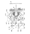
【0007】
このような本発明によれば、密閉構造内部に循環ファンが設けられているので、この循環ファンにより、空気循環路を通して密閉構造内部の空気を強制的に循環させることが可能となる。従って、密閉構造内部を循環する空気と電気光学装置との間で熱交換を行うことにより、電気光学装置を効率的に冷却することが可能となる。また、電気光学装置が上述した密閉構造により密閉されているので、電気光学装置に塵埃等が付着することもなく、画質を長期的に安定して確保することが可能となる。
また、遠心力ファンを採用することにより、排出時の空気の圧力を大きく取ることができるので、その吐出圧力の大きさを利用して密閉構造内部の空気を確実に循環させることが可能となる。また、遠心力ファンは、通常の軸流ファンと比較して吐出圧力が大きいので、低回転で回すことにより、ファンの回転による騒音を最小限に抑えることが可能となる。
さらに、遠心力ファンが電気光学装置の上部に配置され、その吸気面が電気光学装置載置部と対向しているので、電気光学装置は、遠心力ファンの吸い込み側の空気循環流中に配置されることとなり、電気光学装置を一様に冷却することが可能となる。
【0012】
さらに、投写レンズの基端側には、前記投写レンズの径方向外側に向かって突出するフランジが設けられ、このフランジと投写レンズ取付部とを接合することにより、前記投写レンズが前記構造体に取り付けられる場合、上述した遠心力ファンは、フランジの外周端縁から径方向内側の領域に対応する部分に、前記フランジの外周端縁の径方向外側に突出しないように配置されているのが好ましい。
【0013】
すなわち、遠心力ファンがこのように配置されていれば、遠心力ファンがフランジの外側に突出することを防止することが可能となり、密閉構造の小型化を図ることにより、投写型表示装置の小型化、薄型化が図られる。
【0014】
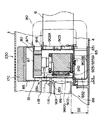
そして、上述した空気循環路は、一端が遠心力ファンの排出口と接続され、他端が密閉部材の下側部分と接続されるパイプ状部材から構成されているのが好ましい。
【0015】
すなわち、空気循環路を構成するパイプ状部材が遠心力ファンの排出口と接続されているので、電気光学装置を冷却して遠心力ファンに吸い込まれた空気のすべてが空気循環路を構成するパイプ状部材中を流通する。従って、このパイプ状部材を投写型表示装置内部の冷却空気の流路中に配置して冷却すれば、パイプ状部材と空気との熱交換により、密閉構造内部の空気を効率的に冷却することが可能となる。そして、冷却された空気を他端の接続部分から噴出することにより、電気光学装置の冷却に供することが可能となる。
【0016】
また、電気光学装置が出射光束を画像情報に応じて変調する複数の光変調装置を備えている場合、上述した密閉部材内部には、複数の光変調装置の配置に応じて空気循環路から噴出される空気を按分する整流板が設けられているのが好ましい。
【0017】
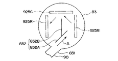
すなわち、整流板が設けられているので、複数の光変調装置の発熱状態に応じて、空気循環路で冷却された空気を案内することが可能となり、電気光学装置の冷却を一層効率的に行うことが可能となる。
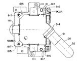
【0018】
さらに、複数の光変調装置が赤、緑、青の各色ごとに変調する赤色光変調装置、緑色光変調装置、および青色光変調装置である場合、上述した整流板は、青色光変調装置、緑色光変調装置、赤色光変調装置の順番で空気循環路から噴出する空気を案内するように構成されているのが好ましい。
【0019】
すなわち、上述した変調素子のうち、青色光変調装置の発熱量が最も高く、次いで、緑色光変調装置、赤色光変調装置の順となる。従って、このような順番で空気循環路からの空気を案内すれば、各光変調装置を必要に応じて、適切に冷却することが可能となる。
【0020】
そして、上述した電気光学装置が光束を画像情報に応じて変調する光変調装置を備えている場合、密閉部材と光変調装置との間には、1mm〜5mmの隙間が形成されているのが好ましく、より好ましくは、該隙間は3mmに設定されているのがよい。
【0021】
すなわち、密閉部材と光変調装置との間にこの程度の隙間が形成されていれば、密閉構造内部の空気をこの隙間に沿って適切に流通させることが可能となるので、電気光学装置を一層効率的に冷却することが可能となる。尚、前記隙間の隙間寸法を5mm以上とすると、隙間中を流れる空気の流速が遅くなってしまい光変調装置を効率的に冷却することができず、隙間寸法を1mm以下とすると、側板部と光変調装置の配置精度の管理が困難となるからである。
【0022】
【発明の実施の形態】
以下、本発明の実施の一形態を図面に基づいて説明する。
【0023】
(1)装置の全体構成
図1、図2には、本実施形態に係る投写型表示装置1の概略斜視図が示され、図1は上面側から見た斜視図、図2は下面側から見た斜視図である。
【0024】
投写型表示装置1は、光源ランプから出射された光束を赤(R)、緑(G)、青(B)の三原色に分離し、これらの各色光束を光変調装置を構成する液晶パネルを通して画像情報に対応させて変調し、変調した後の各色の変調光束をプリズム(色合成光学系)により合成して、投写レンズ6を介して投写面上に拡大表示する形式のものである。投写レンズ6の一部を除いて、各構成部品は外装ケース2の内部に収納されている。
【0025】
(2)外装ケースの構造
外装ケース2は、基本的には、装置上面を覆うアッパーケース3と、装置底面を構成するロアーケース4と、背面部分を覆うリアケース5(図2)とを含んで構成されている。
【0026】
図1に示すように、アッパーケース3の上面において、その前方側(投写レンズ側)の左右の端には、多数の連通孔25R、25Lが形成されている。また、これらの連通孔25R、25L間には、投写型表示装置1の画質等を調整するための操作スイッチ60が設けられている。さらに、この操作スイッチ60の装置後端側には、投写型表示装置1の内部に外部から冷却空気を導入するための空気取入口230が設けられている。尚、図1では図示を略したが、空気取入口230の内面側には、スポンジからなるエアフィルタが設けられ、空気取入口230から塵埃等が内部に侵入するのを防止している。そして、アッパーケース3の前面の向かって左下部分には、図示略のリモートコントローラからの光信号を受信するための受光部70が設けられている。
【0027】
図2に示されるように、ロアーケース4の底面には、内部に収納される光源ランプユニット8(後述)を交換するためのランプ交換蓋27が設けられているとともに、投写型表示装置1の前端の略中央部にはフット31C、および後端の左右の角部にはフット31R、31Lが設けられている。尚、フット31Cは、図1に示すレバー311を上方に引き上げることにより、後方側の回動機構312(図2)によって回動し、図2中の二点鎖線で示すように、前方側が装置本体から離間して開いた状態に付勢される。そして、その回動量を調整することで、投写面上の表示画面の上下方向位置を変更できるようになっている。一方、フット31R、31Lは、回転させることで突出方向に進退する構成であり、その進退量を調整することによって表示画面の傾きを変更することが可能である。
【0028】
リアケース5には、図2に示すように、外部電力供給用のACインレット45や各種の入出力端子群46が配置され、これらの入出力端子群46に隣接して、装置内部の空気を排出する排気口160が形成されている。
【0029】
(3)装置の内部構造
図3、図4には、投写型表示装置1の内部構造が示されている。
【0030】
これらの図に示すように、外装ケース2の内部には、電源としての電源ユニット7、光源ランプユニット8、光学系を構成する光学ユニット10、光変調装置駆動基板としての上下一対のドライバーボード11、制御回路基板としてのメインボード12などが配置されている。
【0031】
電源ユニット7は、投写レンズ6の両側に配置された第1、第2電源ブロック7A、7Bで構成されている。第1電源ブロック7Aは、ACインレット45を通して得られる電力を変圧して主に第2電源ブロック7Bおよび光源ランプユニット8に供給するものであり、トランス(変圧器)、整流回路、平滑回路、電圧安定回路等が形成された電源回路基板の他、光源ランプユニット8の後述する光源ランプ181を駆動するためのランプ駆動基板18を備え、このランプ駆動基板18が透明な樹脂カバー185で覆われている。第2電源ブロック7Bは、第1電源ブロック7Bから得られる電力をさらに変圧して供給するものであり、第1電源ブロック7Aと同様にトランスの他、各種の回路が形成された電源回路基板を備えている。そして、その電力は光学ユニット10の下側に配置された別の電源回路基板13(図4中に点線で図示)および各電源ブロック7A、7Bに隣接配置された第1、第2吸気ファン17A、17Bに供給される。
【0032】
また、電源回路基板13上の電源回路では、第2電源ブロック7Bからの電力を基にして主にメインボード12上の制御回路駆動用の電力を造り出しているとともに、その他の低電力部品用の電力を造り出している。ここで、第2吸気ファン17Bは、第2電源ブロック7Bと投写レンズ6との間に配置されており、投写レンズ6とアッパーケース3(図1)との間に形成される隙間を通して冷却用空気を外部から内部に吸引するように設けられている。そして、各電源ブロック7A、7Bは、アルミ等の導電性を有する電源カバー部材250A、250Bを備え、各電源カバー部材250A、250Bには、アッパーケース3の連通孔25R、25Lに対応する位置に音声出力用のスピーカ251R、251Lが設けられている。これらの電源カバー部材250A、250B同士は、図2中点線で示すように、下部間が金属プレート252Lで電気的に接続され、最終的にインレット45のGND(グランド)ラインを通して接地されている。この金属プレート252Lは、樹脂製のロアーケース4予めに固定されたものであり、その両端が各電源ブロック7A、7Bとロアーケース4とを組み付けることによって電源カバー部材250A、250Bの下面に接触し、互いを導通させている。
【0033】
光源ランプユニット8は、投写型表示装置1の光源部分を構成するものであり、光源ランプおよびリフレクタからなる光源装置と、この光源装置を収納するランプハウジングとを有している。このような光源ランプユニット8は、図4に示す下ライトガイド902と一体に形成された収容部9021で覆われており、上述したランプ交換蓋27から取り外せるように構成されている。収容部9021の後方には、リアケース5の排気口160に対応した位置に一対の排気ファン16が左右に並設されており、後に詳説するが、これらの排気ファン16によって、第1〜第3吸気ファン17A〜17Cで吸引された冷却用空気を収容部9021近傍に設けられた開口部からその内部に導き入れるとともに、この冷却用空気で光源ランプユニット8を冷却した後、その冷却用空気を排気口160から排気している。尚、各排気ファン16の電力は、電源回路基板13から供給されるようになっている。
【0034】
光学ユニット10は、光源ランプユニット8から出射された光束を、光学的に処理して画像情報に対応した光学像を形成するユニットであり、図4に示すように、照明光学系923、色分離光学系924、光変調装置925、および色合成光学系としてのプリズムユニット910を含んで構成される。照明光学系923および色分離光学系924を構成するレンズ、ミラー等の光学素子は、光学部品用筐体となる上下のライトガイドの間に上下に挟まれて保持された構成となっている(図4には、下ライトガイド902のみ図示)。これらの上ライトガイド、下ライトガイド902は一体とされて、ロアーケース4の側に固定ネジにより固定されている。尚、図3および図4では図示を略したが、下ライトガイド902の下面とロアーケース4の内部底面との間には、隙間が設けられ、排気口160と連通している。
【0035】
プリズムユニット910は、構造体となる側面略L字のヘッド体903に固定ネジにより固定され、光変調装置925を構成する3枚の液晶パネルは、プリズムユニット910の側面に固定部材を介して固定されている。このような光変調装置925およびプリズムユニット910を含む電気光学装置は、後に詳述するが、密閉ボックス80およびヘッド体903の投写レンズ6の取付部によって覆われ、光変調装置925から投写レンズ6までの光路が密閉構造とされている。
【0036】
ドライバーボード11は、上述した光変調装置925を構成する3枚の液晶パネルを駆動・制御するためのものであり、光学ユニット10の上方に配置されている。また、下方のドライバーボード11Aと上方のドライバーボード11Bとはスタッドボルト9011を介して離間しており、互いの対向面には駆動回路等を形成する図示しない多くの素子が実装されている。すなわち、それらの多くの素子が各ドライバーボード11間を流通する冷却空気によって効率よく冷却されるようになっている。
【0037】
メインボード12は、投写型表示装置1全体を制御する制御回路が形成されたものであり、光学ユニット10の側方に立設されている。このようなメインボード12は、前述のドライバーボード11、操作スイッチ60と電気的に接続されている他、入出力端子群46が設けられたインターフェース基板14およびビデオ基板15と電気的に接続され、また、コネクター等を介して電源回路基板13に接続されている。そして、メインボード12の制御回路は電源回路基板13上の電源回路で造られた電力、すなわち第2電源ブロック7Bからの電力によって駆動されるようになっている。尚、メインボード12の冷却は、第2吸気ファン17Bから第2電源ブロック7Bを通って流入する冷却用空気で行われる。
【0038】
図3において、メインボード12と外装ケース2(図3ではロアーケース4およびリアケース5のみを図示)との間には、アルミ等の金属製のガード部材19が配置されている。このガード部材19は、メインボード12の上下端にわたる大きな面状部191を有しているとともに、上部側が固定ネジ192で第2電源ブロック7Aのカバー部材250Bに固定され、下端がロアーケース4の例えばスリットに係合支持され、この結果、ロアーケース4にアッパーケース3を取り付ける際にアッパーケース3(図1)とメインボード12との干渉を防ぐ他、メインボード12を外部ノイズから保護している。
【0039】
(4)光学系の構造
次に、投写型表示装置1の光学系即ち光学ユニット10の構造について、図5に示す模式図に基づいて説明する。
【0040】
上述したように、光学ユニット10は、光源ランプユニット8からの光束(W)の面内照度分布を均一化する照明光学系923と、この照明光学系923からの光束(W)を、赤(R)、緑(G)、青(B)に分離する色分離光学系924と、各色光束R、G、Bを画像情報に応じて変調する光変調装置925と、変調後の各色光束を合成する色合成光学系としてのプリズムユニット910とを含んで構成されている。光源ランプユニット8は、光源ランプ181およびリフレクタ182からなる光源装置を備えている。
【0041】
照明光学系923は、光源ランプユニット8から出射された光束Wの中心光軸1aを装置前方向に折り曲げる反射ミラー931と、この反射ミラー931を挟んで配置される第1のレンズ板921および第2のレンズ板922とを備えている
第1のレンズ板921は、マトリクス状に配置された複数の矩形レンズを有しており、光源から出射された光束を複数の部分光束に分割し、各部分光束を第2のレンズ板922の近傍で集光させる。
【0042】
第2のレンズ板922は、マトリクス状に配置された複数の矩形レンズを有しており、第1のレンズ板921から出射された各部分光束を光変調装置925を構成する液晶パネル925R、925G、925B(後述)上に重畳させる機能を有している。
【0043】
このように、本例の投写型表示装置1では、照明光学系923により、液晶パネル925R、925G、925B上をほぼ均一な照度の光で照明することができるので、照度ムラのない投写画像を得ることができる。
【0044】
色分離光学系924は、青緑反射ダイクロイックミラー941と、緑反射ダイクロイックミラー942と、反射ミラー943から構成される。まず、青緑反射ダイクロイックミラー941において、照明光学系923から出射される光束Wに含まれている青色光束Bおよび緑色光束Gが直角に反射され、緑反射ダイクロイックミラー942の側に向かう。
【0045】
赤色光束Rはこの青緑反射ダイクロイックミラー941を通過して、後方の反射ミラー943で直角に反射されて、赤色光束Rの出射部944からプリズムユニット910の側に出射される。次に、青緑反射ダイクロイックミラー941において反射された青色、緑色光束B、Gのうち、緑反射ダイクロイックミラー942において、緑色光束Gのみが直角に反射されて、緑色光束Gの出射部945からプリズムユニット910側に出射される。この緑反射ダイクロイックミラー942を通過した青色光束Bは、青色光束Bの出射部946からリレー光学系927の側に出射される。本例では、照明光学系923の光束Wの出射部から、色分離光学系924における各色光束R、G、Bの出射部944、945、946までの距離が全て等しくなるように設定されている。
【0046】
色分離光学系924の赤色、緑色光束R、Gの出射部944、945の出射側には、それぞれ集光レンズ951、952が配置されている。従って、各出射部から出射した赤色、緑色光束R、Gは、これらの集光レンズ951、952に入射して平行化される。このように平行化された赤色、緑色光束R、Gは、入射側偏光板960R、960Gを通って液晶パネル925R、925Gに入射して変調され、各色光に対応した画像情報が付加される。すなわち、これらの液晶パネル925R、925Gは、前述のドライバーボード11によって画像情報に応じてスイッチング制御されて、これにより、ここを通過する各色光の変調が行われる。一方、青色光束Bは、リレー光学系927を介して対応する液晶パネル925Bに導かれ、ここにおいて、同様に画像情報に応じて変調が施される。尚、本実施形態の液晶パネル925R、925G、925Bとしては、例えば、ポリシリコンTFTをスイッチング素子として用いたものを採用することができる。
【0047】
リレー光学系927は、青色光束Bの出射部946の出射側に配置した集光レンズ954と、入射側反射ミラー971と、出射側反射ミラー972と、これらの反射ミラーの間に配置した中間レンズ973と、液晶パネル925Bの手前側に配置した集光レンズ953とから構成されており、集光レンズ953から出射した青色光束Bは、入射側偏光板960Bを通って液晶パネル925Bに入射して変調される。この際、光束Wの中心光軸1aおよび各色光束R、G、Bの中心光軸1r、1g、1bはほぼ同一平面内に形成されるようになる。そして、各色光束の光路の長さ、すなわち光源ランプ181から各液晶パネルまでの距離は、青色光束Bが最も長くなり、従って、この光束の光量損失が最も多くなる。しかし、リレー光学系927を介在させることにより、光量損失を抑制できる。
【0048】
次に、各液晶パネル925R、925G、925Bを通って変調された各色光束R、G、Bは、出射側偏光板961R、961G、961Bを通ってプリズムユニット910に入射され、ここで合成される。すなわち、プリズムユニット910は、内部に略X字状に配置された2種類の波長選択膜を有するプリズムを備え、これら2種類の波長選択膜の選択特性によって、各色光束R、G、Bが合成される。そして、このプリズムユニット910によって合成されたカラー画像が投写レンズ6を介して所定の位置にある投写面100上に拡大投写されるようになっている。
【0049】
(5)密閉ボックス80およびヘッド体903の構造
密閉ボックス80およびヘッド体903は、図6に示すように、上ライトガイド901および下ライトガイド902から構成されるライトガイドに隣接配置されている。密閉ボックス80および構造体となるヘッド体903により区画される密閉構造の内部には、光変調装置925およびプリズムユニット910を含む電気光学装置が密閉収納されている。また、プリズムユニット910の平面位置に対応するアッパーケース3の上面には、上述した空気取入口230が形成されているとともに、密閉ボックス80および空気取入口230の間には、吸気ファン17Cが配置されている。さらに、ライトガイドと、密閉ボックス80との境界部分には、寸法D1の隙間が形成されこの隙間が冷却空気導入路86とされている。この冷却空気導入路86は、ロアーケース4の内部底面および下ライトガイド902の下面の間の寸法D2の隙間として形成される排気流路88と連通している。尚、密閉ボックス80の平面形状は、吸気ファン17Cのファン径よりも小さく設定され、これにより、吸気ファン17Cからの冷却空気が冷却空気導入路86に流れやすくなっている。また、冷却空気導入路86の隙間寸法D1は、吸気ファン17Cの送風量、密閉構造内部の容積によって定められ、1mm〜10mm程度に設定するのが好ましく、投写型表示装置1の内部の収納効率を考慮すれば、3mm〜5mmに設定するのが最も好ましい。そして、上ライトガイド901の境界部分と吸気ファン17Cとの間には、上述した冷却空気導入路を囲むようにカバー部材85が設けられ、吸気ファン17Cにより空気取入口230から取り入れられた冷却空気は、このカバー部材85により冷却空気導入路86に案内される。尚、このカバー部材85の側面には、冷却空気の一部を導く冷却空気導入用開口851が形成され、この冷却空気導入用開口851により導かれる冷却空気の一部は、上述したドライバーボード11に案内されてこれらを冷却する。
【0050】
構造体となるヘッド体903は、マグネシウム合金製の側面略L字の部材であり、略L字の垂直部分が投写レンズ6が固定される投写レンズ取付部903Aとされ、略L字の水平部分が電気光学装置が載置固定される電気光学装置載置部903Bとされる。尚、図6では図示を略したが、投写レンズ6の基端側には、投写レンズ6の径方向外側に向かうフランジが形成され、このフランジと投写レンズ取付部903Aが固定ねじにより接合されて、投写レンズ6は投写レンズ取付部903Aに取り付けられている。また、投写レンズ取付部903Aと投写レンズ6との間には、シール材が設けられ、投写レンズ取付部903Aの図6中左側および右側の空間における空気の流通が規制されるようになっている。さらに、電気光学装置載置部903Bには、液晶パネル925R、925G、925Bの配置に応じて複数の連通孔が形成され、電気光学装置載置部903Bにより区画される上下の空間の空気の流通が確保されている。
【0051】
密閉ボックス80は、マグネシウム合金製の上カバー部材81および下カバー部材83から構成され、図6に示すように、上カバー部材81の上面下側には、密閉構造内の空気を循環させるために、遠心力ファン87が設けられている。この遠心力ファン87は、ファンの回転軸に沿った方向から空気を吸引し、ファンの回転接線方向に空気を排出するものであり、空気を排出する排出口871は、上カバー部材81の接続部814を介して空気循環路90と接続され、各接続部分にはシール材が介在して密閉性が確保される。尚、本例の場合、遠心力ファン87としては、最大流量が0.17m3/min、排出口871における最大静圧が17.5mmAqのものを採用している。密閉構造内部の空気は、遠心力ファン87によって吸引され、空気循環路90から排出され、再び下カバー部材83から密閉構造内部に供給される。
【0052】
上カバー部材81は、図7に示すように、液晶パネル925R、925G、925Bを囲むように配置される側板部811と、この側板部811の上面を覆う上板部821から構成されている。液晶パネル925R、925G、925Bの配置に対応する側板部811の部分には、赤色光束R、緑色光束G、および青色光束Bを導入するために、3つの開口部812が形成されている。また、図7では図示を略したが、各開口部812には、ガラス板が貼り付けられ、その内側に上述した入射側偏光板960R、960G、960Bが貼り付けられている。ガラス板は、側板部811に対して、シール材を介して貼り付けられ、密閉構造内外の空気の流通を遮断している。
【0053】
さらに、図6に示すように、側板部811と各液晶パネル925R、925G、925Bとの間には、隙間が設けられ、その隙間寸法D3は、略3mmに設定されている。これは、図8に示すように、隙間寸法D3が小さくなると、隙間の間を流れる空気の風速が大きくなり、風速が大きくなれば、各液晶パネル925R、925G、925Bの冷却効率が向上する点を考慮して設定している。本例の場合、隙間寸法D3を3mmとしたのは、側板部811、各液晶パネル925R、925G、925B等の取付公差を考慮したためであり、高精度の取付が可能であれば、それ以下としてもよい。尚、図8中、グラフG1は遠心力ファン87を最大電圧で回転させた場合、グラフG2は遠心力ファン87を基準電圧で回転させた場合、グラフG3は遠心力ファン87を最小電圧で回転させた場合における隙間部分の風速の変化である。
【0054】
また、図7に示すように、3つの開口部812の上部には、液晶パネル925R、925G、925Bとドライバーボード11Aとを電気的に接続するフレキシブルプリントケーブル(FPC)111を挿通するために、切欠部813が形成されている。さらに、側板部811の上部前面には、空気循環路90を接続するための接続部814が形成されている。上板部821は、側板部811の上面を覆う平板状部分823と、その外周の側板部811の切欠部813の位置に対応する位置に設けられ、当該切欠部813と係合する係合片822とを含んで構成される。そして、係合片822を切欠部813に挿入すると、FPC111が係合片822と側板部811との間に狭持される。FPC111の周りには不図示のゴムパッキンが取り付けられており密閉構造内部の気密性を確保している。尚、本実施形態では、上カバー部材81の側板部811と上板部821とを別部材によって構成しているが、これらを一体化した部材で構成してもよい。
【0055】
下カバー部材83は、ヘッド体903の底部を覆う円筒箱状部材であり、その前方側面には、上カバー部材81と同様に、空気循環路90を接続する接続部831が形成されている。また、下カバー部材83の内部には、仕切板832が設けられ、空気循環路90からの空気を案内する整流板となっている。具体的には、図9に示すように、仕切板832の配置は、空気循環路90からの空気の噴出方向、液晶パネル925R、925G、925Bの配置によって決定され、本例の場合、空気循環路90から噴出された空気Aは、仕切板832Aによって液晶パネル925Bの下部に案内され、続けて仕切板832Bによって液晶パネル925G、925Rの下部に案内される。
【0056】
上述した上カバー部材81および下カバー部材83は、ヘッド体903に取り付けられる。上カバー部材81は、電気光学装置載置部903Bの上面側(プリズムユニット910側)、および投写レンズ取付部903Aの投写レンズ6が取り付けられる面とは反対側の面に取り付けられ、下カバー部材83は、電気光学装置載置部903Bの下面側(プリズムユニット910とは反対側)に取り付けられる。上カバー部材81は、図10に示すように、側板部811の底部に設けられる固定片815と、側板部811の中間部分に設けられる固定片816とを有し、これらの固定片815、816をボルト817によってヘッド体903の電気光学装置載置部903Bおよび投写レンズ取付部903Aに固定する。このため、上カバー部材81平面形状は、固定片815が設けられる部分が面取りされた矩形状とされ、ボルト817の螺合固定を容易にしている。また、図10では図示を略したが、上カバー部材81の電気光学装置載置部903Bおよび投写レンズ取付部903Aとの接触部分には、ゴムパッキン等のシール部材が介在しており、このシール部材により、上カバー部材81の内外の密閉性が確保される。下カバー部材83のヘッド体903に対する取付構造も上カバー部材81の取付構造と略同様なので、その説明を省略する。
【0057】
(6)空気循環路90の構造
空気循環路90は、図10に示すように、アルミニウム製のパイプ状部材91、エルボ92から構成され、その端部が上カバー部材81の接続部814および下カバー部材83の接続部831とシール材を介して接続されている。
【0058】
ここで、パイプ状部材91の内径は、遠心力ファン87により密閉構造内の空気を循環させた場合、光変調装置925の3枚の液晶パネル925R、925G、925Bの温度がどれだけ上昇するかで決定している。具体的には、図11に示すように、パイプ状部材91の内径を11mm〜17mmに変化させた場合の基準温度に対する温度上昇率で評価している。尚、図11中、グラフG4は液晶パネル925Rの入射面温度の上昇率、グラフG5は液晶パネル925Gの入射面温度の上昇率、グラフG6は液晶パネル925Bの入射面温度の上昇率を表し、グラフG7は密閉ボックス80内部の空気代表温度を表している。図11に示されるように、パイプ状部材91の内径を大きくすれば、各液晶パネル925R、925G、925Bの温度上昇率を少なくすること、つまり効率よく冷却することができることが判る。しかし、上述した遠心力ファン87の排出口871の面積よりも大きくなるように、パイプ状部材91の内径を設定すると、スペース的に無駄な部分が生じてしまうので、排出口871の開口面積に応じてパイプ状部材91の内径を設定するのが好ましく、遠心力ファン87の仕様に応じて、10mm〜30mm程度に設定するのがよい。尚、本例の場合、上述した仕様の遠心力ファン87の排出口871の開口面積を考慮してパイプ状部材91の内径を17mmに設定してある。また、本実施形態は、画像表示に用いられる部分の対角長さが0.9インチの液晶パネルを前提とした条件であり、前記表示部分のサイズが増減するのに伴い、使用する遠心力ファンの能力を増減し、これに伴い、排出口871の開口面積に適合するパイプ状部材91の内径も増減する。
【0059】
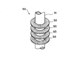
また、図9および図10では図示を略しているが、図12に示すように、パイプ状部材の外周には、複数の放熱フィン93から構成される放熱構造が設けられている。この放熱フィン93は、空気循環路90の外周面に溶接等により接合されるアルミニウム製のリング状部材であり、放熱フィン93の数は、空気循環路90内部の空気の冷却効率に応じて適宜設定される。
【0060】
(7)冷却流路の説明
次に、投写型表示装置1に形成される冷却流路について説明する。
【0061】
投写型表示装置1においては、図1、図2に矢印で模式的に示すように、主に第1電源ブロック冷却流路41、第2電源ブロック冷却流路42、光変調装置冷却流路43、および光源冷却流路44が形成されている。ただし、各冷却流路41〜44を流通する冷却空気は、図中の矢印に沿って厳密に流通するものではなく、各構成部品間の間隙をぬって概ね矢印のように吸排出されるものである。
【0062】
第1電源ブロック冷却流路41は、第1吸気ファン17A(図3、図4)によって吸気口171から吸引された冷却空気の流路である。その冷却空気は、第1電源ブロック7Aを冷却した後、その背後に配置されたランプ駆動基板18を冷却する。この際、冷却空気は、前後両端が開口した樹脂カバー185内を流通することで流れが一方向に規制され、これによってランプ駆動基板18を冷却するための流量が確実に維持されるようになっている。この後、冷却空気は、収容部9021の上部に設けられた開口部9022や、図示しない他の開口部、あるいは隙間等から収容部9021内に流入し、その内部に配置された光源ランプユニット8(光源ランプ181)を冷却し、そして、排気ファン16によって排気口160から排気される。
【0063】
第2電源ブロック冷却流路42は、第2吸気ファン17Bで吸引された冷却空気の流路であり、吸引された冷却空気は、まず、投写レンズ6の側方に配置される空気循環路90を冷却した後、第2電源ブロック7Bに供給される。そして、この冷却空気は、第2電源ブロック7Bを冷却した後、その背後に配置されたメインボード12を冷却し、さらに、収容部9021近傍の開口部9023等からその内部に流入して光源ランプユニット8を冷却し、排気ファン16で排気口160から排気される。
【0064】
光変調装置冷却流路43は、図6に示す第3吸気ファン17Cで吸引された冷却空気の流路である。第3吸気ファン17Cからの冷却空気は、カバー部材85を介して冷却空気導入路86に供給され、密閉ボックス80全体を冷却するとともに、一部が冷却空気導入用開口851に流れてドライバーボード11(11A、11B)を冷却する。密閉ボックス80を冷却した冷却空気は、ロアーケース4の底部に至り、前述の排気流路88を通って排気ファン16によって排気口160から外部に放出される。一方、ドライバーボード11を冷却した冷却空気は、上ライトガイド901の上面に沿って流れ、前記開口部9022、9023などに加え、もう一つの開口部9024をも通って収容部9021内に流入して光源ランプ181を冷却した後、同様に排気口160から放出される。尚、カバー部材85の一部に、パイプ状部材91側に冷却空気を流す開口部を設けて、ファン17Bによってパイプ状部材91に沿った空気流路を形成すれば、一層密閉ボックス80の冷却効率の向上が図られる。また、スペース上ファン17Cを配置できない場合は、ファン17Bだけでも実用上問題ない冷却が得られる。
【0065】
光源冷却流路44は、ロアーケース4の下面の吸気口172(図2)から吸引された冷却空気の流路である。そして、この冷却空気は、排気ファン16によって吸引されるものであり、吸気口172から吸引された後に、収容部9021の下面に設けられた開口部や隙間からその内部に流入して光源ランプユニット8を冷却し、排気口160から排気される。
【0066】
以上のような各冷却流路41〜44の冷却空気は、各排気ファン16によって排気口160から排気されるが、これらの排気ファン16は加熱部品の温度状態に応じて制御されている。つまり、温度が上がり易い光源ランプユニット8側の開口部9022近傍にはシュリンクチューブ等で被覆された温度センサ9025が設けられ、また、開口部9023の下方の第2のレンズ板922(図4)近傍や、第1、第2電源ブロック7A、7B、液晶パネル925R、925G、925B近傍にも同様な温度センサ(図示せず)が設けられており、各冷却流路41〜44内にあるこれらの温度センサ9025からの電気信号が例えば電源回路基板13等を介してメインボード12に出力される。そして、メインボード12では、この信号を電気的に処理して発熱部品あるいは冷却用空気の温度を検出し、その結果、温度が高いと判断した場合には、両方の排気ファン16を同時に駆動させてより積極的に冷却し、低いと判断した場合には、一方の排気ファン16のみを駆動して省電力化を図る等の制御を行っている。
【0067】
(8)密閉構造内部の空気の循環
次に、密閉ボックス80およびヘッド体903から構成される密閉構造内部の空気の循環および冷却について説明する。
【0068】
遠心力ファン87の旋回により密閉構造内部の空気が吸い上げられ、光変調装置925を構成する液晶パネル925R、925G、925Bを冷却する。光変調装置925を冷却した空気は、排出口871から空気循環路90に排出される。空気循環路90は前述の第2電源ブロック冷却流路42を流れる冷却空気によって冷却されているため、光変調装置925の冷却後の空気は、空気循環路90内を流れる間に、その熱が空気循環路90に吸収され、さらに、空気循環路90とその外部を流れる冷却空気との間で熱交換が行われることによって冷却される。その後、この空気は、仕切板832によって、液晶パネル925Bの下部、液晶パネル925Gの下部、液晶パネル925Rの下部の順に流れ、これらの光変調装置925の冷却に供される。尚、第3吸気ファン17Cからの冷却空気により、密閉ボックス80も冷却されているので、密閉構造内部の空気は、その熱が密閉ボックス80に吸収され、さらに、密閉ボックス80とその外部の冷却空気との間で熱交換が行われることによって冷却される。
【0069】
(9)実施形態の効果
前述のような本実施形態によれば、以下のような効果がある。
【0070】
すなわち、密閉構造内部に循環ファンとなる遠心力ファン87が設けられているので、空気循環路90を通じて密閉構造内部の空気を強制的に循環させることができる。従って、密閉構造内部を循環する空気と液晶パネル925R、925G、925Bとの間で熱交換を行うことにより、液晶パネル925R、925G、925Bを含む電気光学装置を効率的に冷却することができる。また、電気光学装置がヘッド体903および密閉ボックス80からなる密閉構造により密閉されているので、電気光学装置に塵埃等が付着することもなく、画質を長期的に安定して確保することができる。
【0071】
また、密閉構造内部の強制的な循環装置として遠心力ファン87を採用することにより、排出口871からの排出空気の圧力を大きく取ることができるので、その吐出圧力の大きさを利用して密閉構造内部の空気を確実に循環させることができる。そして、遠心力ファン87は、通常の軸流ファンと比較して吐出圧力が大きいので、低回転で回すことにより、ファンの回転による騒音を最小限に抑えることができる。
【0072】
さらに、遠心力ファン87が電気光学装置の上部に配置され、その吸気面が電気光学装置と対向しているので、遠心力ファン87の吸い込み側の空気循環流中に配置されることとなり、電気光学装置を構成する光変調装置925の液晶パネル面を一様に冷却することができる。
【0073】
そして、空気循環路90を構成するパイプ状部材91が遠心力ファン87と接続されているので、電気光学装置を冷却して遠心力ファン87に吸い込まれた空気のすべてがパイプ状部材91中を流通することとなる。従って、空気循環路90が第2電源ブロック冷却流路42中に配置され、投写型表示装置内部を流れる冷却空気により冷却されるので、パイプ状部材91と空気との熱交換により、密閉構造内部の空気を効率的に冷却することができる。そして、冷却された空気を、空気循環路90の他端の接続部831から噴出することにより、電気光学装置の冷却に供することができる。
【0074】
また、下カバー部材83内部に整流板となる仕切板832が設けられているので、液晶パネル925R、925G、925Bの配置に応じて、空気循環路90の接続部831から噴出された空気を案内することができ、電気光学装置の冷却を一層効率的に行うことができる。特に、該仕切板832が青色光束を変調する液晶パネル925B、緑色光束を変調する液晶パネル925G、赤色光束を変調する925Rの順番で空気を案内するように構成されているので、発熱量が大きい順番で適切に液晶パネル925R、925G、925Bを冷却することができる。
【0075】
さらに、密閉ボックス80の側板部811と液晶パネル925R、925G、925Bの間の隙間寸法D3が3mm程度に設定されているので、隙間を流れる空気の風速を十分確保して液晶パネル925R、925G、925Bを適切に冷却することができる。
【0076】
(10)実施形態の変形
尚、本発明は、前述の実施形態に限定されるものではなく、以下に示すような変形をも含むものである。
【0077】
すなわち、前記実施形態では、密閉構造内部に配置される循環ファンは遠心力ファン87であったが、これに限らず、投写型表示装置内部の冷却に通常用いられる軸流ファンを採用してもよい。
【0078】
また、前記実施形態では、遠心力ファン87は、ヘッド体903の投写レンズ取付部903Aから突出して設けられていたが、これに限られない。すなわち、投写レンズ6の基端側に前記投写レンズの径方向外側に向かって突出するフランジが設けられ、このフランジと投写レンズ取付部903Aとを接合することにより、投写レンズ6が構造体903に取り付けられる場合、遠心力ファンを、フランジの外周端縁の径方向内側の領域に対応する部分に、フランジの外周端縁の径方向外側に突出しないように配置してもよい。
【0079】
遠心力ファンをこのように配置すれば、密閉構造の高さ寸法を小さくすることができるので、投写型表示装置の小型化および薄型化を図り易い。
【0080】
さらに、前記実施形態では、光変調装置925は、TFT駆動の液晶パネル925R、925G、925Bから構成されていたが、これに限らず、TN、STN等他の駆動方式から構成される光変調装置を備えた投写型表示装置に本発明を採用してもよい。
【0081】
また、前記実施形態では、光変調装置925は、3枚の液晶パネル925R、925G、925Bから構成されていたが、これに限らず、1枚、2枚の液晶パネルから構成される光変調装置に本発明を採用してもよい。
【0082】
そして、前記実施形態では、光変調装置925を構成するパネルは液晶素子から構成されていたが、液晶以外のプラズマ素子、マイクロミラーを用いたパネルから構成される光変調装置を備えた投写型表示装置に本発明を採用してもよい。
【0083】
また、前記実施形態における光変調装置925は、光束R、G、Bを透過して変調する形式のものであったが、これに限らず、入射した光を反射しつつ変調して出射する反射型の光変調装置を備えた投写型表示装置に本発明を採用してもよい。
【0084】
その他、本発明の実施の際の具体的な構造および形状等は、本発明の目的を達成できる範囲で他の構造等としてもよい。
【0085】
【発明の効果】
前述のような本発明の投写型表示装置によれば、密閉構造内部に循環ファンが設けられているので、この循環ファンにより、空気循環路を通して密閉構造内部の空気を強制的に循環させることができ、密閉構造内部を循環する空気と電気光学装置との間で熱交換を行うことにより、電気光学装置を効率的に冷却することができる。また、電気光学装置が上述した密閉構造により密閉されているので、電気光学装置に塵埃等が付着することもなく、画質を長期的に安定して確保することができる。
【図面の簡単な説明】
【図1】本発明の実施形態に係る投写型表示装置の上部から見た外観斜視図である。
【図2】前記実施形態における投写型表示装置の下部から見た外観斜視図である。
【図3】前記実施形態における投写型表示装置の内部構造を表す斜視図である。
【図4】前記実施形態における投写型表示装置の内部の光学系を表す斜視図である。
【図5】前記実施形態における光学系の構造を説明するための模式図である。
【図6】前記実施形態における密閉部の構造を表す垂直断面図である。
【図7】前記実施形態における密閉部の外観斜視図である。
【図8】前記実施形態における密閉部材と光変調装置との間の隙間の隙間寸法と、その隙間を流れる空気の風速との関係を表すグラフである。
【図9】前記実施形態における密閉部を構成する下カバー部材の内部構造を表す平面図である。
【図10】前記実施形態における密閉部を構成する上カバー部材の取付構造を表す平面図である。
【図11】前記実施形態における空気循環路を構成するパイプ状部材の内径と、密閉部内部の光変調装置の温度上昇率との関係を表すグラフである。
【図12】前記実施形態における空気循環路に設けられる放熱構造を表す斜視図である。
【符号の説明】
1 投写型表示装置
6 投写レンズ
80 密閉ボックス(密閉部材)
87 遠心力ファン(循環ファン)
90 空気循環路
91 パイプ状部材
181 光源ランプ(光源)
832仕切板(整流板)
871 排出口
903A 投写レンズ取付部
903B 電気光学装置載置部
925 光変調装置
W 光束[0001]
BACKGROUND OF THE INVENTION
The present invention relates to a projection display device including a light source, an electro-optical device that modulates a light beam emitted from the light source according to image information, and a projection lens that magnifies and projects an image formed by the electro-optical device. About.
[0002]
[Background]
2. Description of the Related Art Conventionally, there is provided a projection display device that includes a light source, an optical system that modulates a light beam emitted from the light source according to image information to form an optical image, and a projection lens that magnifies and projects the modulated light beam. It's being used. The optical system is an illumination optical system that equalizes the in-plane illuminance distribution of the luminous flux emitted from the light source, a color separation optical system that separates the luminous flux from this illumination optical system into the three primary colors of red, blue, and green, and each color luminous flux as image information And a color synthesizing optical system for synthesizing the modulated color light beams. The light modulation system includes three light modulation devices that modulate the red light beam, the blue light beam, and the green light beam separated by the color separation optical system in accordance with image information.
[0003]
In such a light modulation device, for example, a light modulation element such as a liquid crystal panel using a polysilicon TFT as a switching element is employed. Since this light modulation device is an important part that forms an optical image according to image information, if dust, oily smoke, etc. adhere to the surface of a liquid crystal panel or the like, the image quality of the projection display device deteriorates. is there. For this reason, it is conceivable to employ a projection display device having a sealing portion that seals the optical path from the light modulation device to the projection lens. In the projection display device having such a sealing portion, dust and oily smoke can be prevented from entering from the outside by the sealing portion, so that dust, oily smoke and the like may adhere to the liquid crystal panel surface of the light modulation device. Therefore, the image quality of the projection display device can be ensured stably for a long period of time, and it is suitable as a stationary projection display device such as a ceiling hanging type.For example, as described in
[Patent Document 1]
Published Patent Publication "JP-A-8-275096" (Eighth − 9 pages 9 Figure)
[0004]
[Problems to be solved by the invention]
However, since a light modulation device such as a liquid crystal panel is generally vulnerable to heat, as described above, if the optical path from the light modulation device to the projection lens is sealed by a sealed structure, cooling air is introduced from the outside of the device. Therefore, there is a problem that it is difficult to efficiently cool the light modulation device. In particular, in the recent trend of increasing the brightness and downsizing of projection display devices, it is an important problem to efficiently cool the light modulation device.
[0005]
An object of the present invention includes a light source, a light modulation device that modulates a light beam emitted from the light source according to image information, and a projection lens that enlarges and projects an image formed by the light modulation device on a projection surface. Another object of the present invention is to provide a projection display device that can efficiently cool the light modulation device and can ensure the image quality stably over the long term.
[0006]
[Means for Solving the Problems]
A projection display device according to the present invention includes a light source, an electro-optical device that modulates a light beam emitted from the light source according to image information, and a projection lens that magnifies and projects an image formed by the electro-optical device. An electro-optical device mounting portion on which the electro-optical device is mounted, and a projection lens mounting that is provided substantially perpendicular to the electro-optical device mounting portion and mounts the projection lens A structure provided with a portion, a sealing member attached to the electro-optical device portion and sealing an optical path from the electro-optical device to the projection lens, and connected to the sealing member, the structure and the sealing member ComposedSealed structureAn air circulation path for circulating internal air; andSealed structureWith a circulation fan arranged insideThe circulation fan is a centrifugal fan that discharges air taken in by rotation of the fan in a tangential direction of rotation, and the centrifugal fan is disposed at an upper portion of the electro-optical device, and an intake surface of the centrifugal fan is the electro-optical device Opposite to the device mounting partIt is characterized by.
[0007]
According to the present invention as described above,Sealed structureSince a circulation fan is provided inside, this circulation fan allows air to pass through the air circulation path.Sealed structureIt is possible to forcibly circulate the internal air. Therefore,Sealed structureBy performing heat exchange between the air circulating inside and the electro-optical device, the electro-optical device can be efficiently cooled. Also, the electro-optical device described aboveSealed structureTherefore, dust and the like do not adhere to the electro-optical device, and the image quality can be ensured stably for a long period of time.
Further, by adopting the centrifugal fan, it is possible to increase the pressure of the air at the time of discharge, so that it is possible to reliably circulate the air inside the sealed structure using the magnitude of the discharge pressure. . In addition, since the centrifugal fan has a higher discharge pressure than a normal axial fan, it is possible to minimize the noise caused by the rotation of the fan by rotating at a low speed.
Furthermore, since the centrifugal fan is arranged at the upper part of the electro-optical device and the suction surface faces the electro-optical device mounting portion, the electro-optical device is arranged in the air circulation flow on the suction side of the centrifugal fan. As a result, the electro-optical device can be uniformly cooled.
[0012]
Further, a flange projecting outward in the radial direction of the projection lens is provided on the proximal end side of the projection lens, and the projection lens is attached to the structure by joining the flange and the projection lens mounting portion. When attached, the centrifugal fan described above is preferably arranged in a portion corresponding to the radially inner region from the outer peripheral edge of the flange so as not to protrude radially outward of the outer peripheral edge of the flange. .
[0013]
That is, if the centrifugal fan is arranged in this way, it is possible to prevent the centrifugal fan from protruding outside the flange,Sealed structureBy downsizing, the projection display device can be reduced in size and thickness.
[0014]
And it is preferable that the air circulation path mentioned above is comprised from the pipe-shaped member by which one end is connected with the discharge port of a centrifugal fan and the other end is connected with the lower part of a sealing member.
[0015]
That is, since the pipe-shaped member that forms the air circulation path is connected to the outlet of the centrifugal fan, the pipe that forms the air circulation path is all the air that has cooled the electro-optical device and has been sucked into the centrifugal fan It circulates in the shaped member. Therefore, if this pipe-shaped member is arranged and cooled in the flow path of the cooling air inside the projection display device, heat exchange between the pipe-shaped member and the air results in:Sealed structureIt becomes possible to cool the internal air efficiently. And it becomes possible to use for cooling of an electro-optical apparatus by ejecting the cooled air from the connection part of the other end.
[0016]
Further, when the electro-optical device includes a plurality of light modulation devices that modulate the emitted light beam according to the image information, the above-described sealing member is ejected from the air circulation path according to the arrangement of the plurality of light modulation devices. It is preferable that a rectifying plate is provided to apportion the air to be generated.
[0017]
That is, since the rectifying plate is provided, it becomes possible to guide the air cooled in the air circulation path according to the heat generation state of the plurality of light modulation devices, and the electro-optical device is cooled more efficiently. It becomes possible.
[0018]
Further, when the plurality of light modulation devices are a red light modulation device, a green light modulation device, and a blue light modulation device that modulates each color of red, green, and blue, the rectifying plate described above includes a blue light modulation device, a green light modulation device, and a green light modulation device. It is preferable that the air ejected from the air circulation path is guided in the order of the light modulation device and the red light modulation device.
[0019]
That is, among the modulation elements described above, the blue light modulation device has the highest heat generation amount, followed by the green light modulation device and then the red light modulation device. Therefore, if the air from the air circulation path is guided in this order, each light modulation device can be appropriately cooled as necessary.
[0020]
When the electro-optical device described above includes a light modulation device that modulates a light beam according to image information, a gap of 1 mm to 5 mm is formed between the sealing member and the light modulation device. More preferably, the gap is set to 3 mm.
[0021]
That is, if a gap of this degree is formed between the sealing member and the light modulation device,Sealed structureSince the internal air can be appropriately distributed along the gap, the electro-optical device can be cooled more efficiently. If the gap dimension of the gap is 5 mm or more, the flow rate of air flowing in the gap is slowed down, and the light modulation device cannot be efficiently cooled. If the gap dimension is 1 mm or less, the side plate portion This is because it becomes difficult to manage the arrangement accuracy of the light modulation device.
[0022]
DETAILED DESCRIPTION OF THE INVENTION
Hereinafter, an embodiment of the present invention will be described with reference to the drawings.
[0023]
(1) Overall configuration of the device
1 and 2 are schematic perspective views of a
[0024]
The
[0025]
(2) Exterior case structure
The
[0026]
As shown in FIG. 1, on the upper surface of the
[0027]
As shown in FIG. 2, a
[0028]
As shown in FIG. 2, the
[0029]
(3) Internal structure of the device
3 and 4 show the internal structure of the
[0030]
As shown in these drawings, the
[0031]
The
[0032]
In the power supply circuit on the power
[0033]
The light
[0034]
The
[0035]
The
[0036]
The
[0037]
The
[0038]
3, a
[0039]
(4) Structure of optical system
Next, the structure of the optical system of the
[0040]
As described above, the
[0041]
The illumination
The
[0042]
The
[0043]
As described above, in the
[0044]
The color separation
[0045]
The red light beam R passes through the blue-green reflecting
[0046]
Condensing
[0047]
The relay
[0048]
Next, the color light beams R, G, and B modulated through the
[0049]
(5) Structure of sealed
As shown in FIG. 6, the sealed
[0050]
The
[0051]
The sealed
[0052]
As shown in FIG. 7, the
[0053]
Furthermore, as shown in FIG. 6, a gap is provided between the
[0054]
Further, as shown in FIG. 7, in order to insert a flexible printed cable (FPC) 111 that electrically connects the
[0055]
The
[0056]
The
[0057]
(6) Structure of
As shown in FIG. 10, the
[0058]
Here, the inner diameter of the pipe-shaped
[0059]
Although not shown in FIGS. 9 and 10, as shown in FIG. 12, a heat radiation structure including a plurality of
[0060]
(7) Description of cooling channel
Next, the cooling flow path formed in the
[0061]
In the
[0062]
The first power supply
[0063]
The second power supply block
[0064]
The light modulation device
[0065]
The light
[0066]
The cooling air in the
[0067]
(8) Air circulation inside the sealed structure
Next, air circulation and cooling inside the sealed structure composed of the sealed
[0068]
By turning the
[0069]
(9) Effects of the embodiment
According to this embodiment as described above, the following effects are obtained.
[0070]
That is, since the
[0071]
Further, by adopting the
[0072]
Furthermore, since the
[0073]
Since the pipe-shaped
[0074]
In addition, since a
[0075]
Further, the gap dimension D3 between the
[0076]
(10) Modification of the embodiment
In addition, this invention is not limited to the above-mentioned embodiment, It includes the deformation | transformation as shown below.
[0077]
That is, in the above embodiment, the circulation fan disposed inside the sealed structure is the
[0078]
In the above embodiment, the
[0079]
If the centrifugal fan is arranged in this way, the height of the sealed structure can be reduced, so that the projection display device can be easily reduced in size and thickness.
[0080]
Furthermore, in the above-described embodiment, the
[0081]
In the above-described embodiment, the
[0082]
In the embodiment, the panel constituting the
[0083]
The
[0084]
In addition, the specific structure, shape, and the like when implementing the present invention may be other structures as long as the object of the present invention can be achieved.
[0085]
【The invention's effect】
According to the projection display device of the present invention as described above, since the circulation fan is provided inside the sealed structure, the circulation fan can forcibly circulate the air inside the sealed structure through the air circulation path. The electro-optical device can be efficiently cooled by exchanging heat between the air circulating in the sealed structure and the electro-optical device. In addition, since the electro-optical device is sealed by the above-described sealing structure, dust or the like does not adhere to the electro-optical device, and the image quality can be ensured stably for a long time.
[Brief description of the drawings]
FIG. 1 is an external perspective view of a projection display device according to an embodiment of the present invention as viewed from above.
FIG. 2 is an external perspective view of the projection display device according to the embodiment as viewed from below.
FIG. 3 is a perspective view showing an internal structure of the projection display device in the embodiment.
FIG. 4 is a perspective view showing an optical system inside the projection display apparatus in the embodiment.
FIG. 5 is a schematic diagram for explaining the structure of an optical system in the embodiment.
FIG. 6 is a vertical sectional view showing the structure of the sealing portion in the embodiment.
FIG. 7 is an external perspective view of a sealing portion in the embodiment.
FIG. 8 is a graph showing a relationship between a gap size of a gap between the sealing member and the light modulation device in the embodiment and a wind speed of air flowing through the gap.
FIG. 9 is a plan view showing an internal structure of a lower cover member that constitutes a sealed portion in the embodiment.
FIG. 10 is a plan view showing an attachment structure of an upper cover member that constitutes a sealed portion in the embodiment.
FIG. 11 is a graph showing the relationship between the inner diameter of the pipe-shaped member constituting the air circulation path in the embodiment and the temperature increase rate of the light modulation device inside the sealed portion.
FIG. 12 is a perspective view showing a heat dissipation structure provided in the air circulation path in the embodiment.
[Explanation of symbols]
1 Projection display
6 Projection lens
80 Sealed box (sealing member)
87 Centrifugal fan (circulation fan)
90 Air circulation path
91 Pipe-shaped member
181 Light source lamp (light source)
832 partition plate (rectifier plate)
871 outlet
903A Projection lens mounting part
903B Electro-optical device placement unit
925 light modulator
W luminous flux
Claims (6)
前記電気光学装置を載置する電気光学装置載置部、および前記電気光学装置載置部に対して略垂直に設けられ、前記投写レンズを取り付ける投写レンズ取付部を備えた構造体と、
前記電気光学装置部に取り付けられ、前記電気光学装置から前記投写レンズまでの光路を密閉する密閉部材と、
この密閉部材に接続され、前記構造体および前記密閉部材により構成される密閉構造内部の空気を循環させる空気循環路と、
前記密閉構造内部に配置される循環ファンとを備え、
前記循環ファンは、ファンの回転により取り込まれた空気を回転の接線方向に排出する遠心力ファンであり、
前記遠心力ファンは前記電気光学装置の上部に配置され、その吸気面が当該電気光学装置載置部と対向していることを特徴とする投写型表示装置。A projection display device comprising a light source, an electro-optical device that modulates a light beam emitted from the light source according to image information, and a projection lens that enlarges and projects an image formed by the electro-optical device,
An electro-optical device mounting portion for mounting the electro-optical device, and a structure including a projection lens mounting portion that is provided substantially perpendicular to the electro-optical device mounting portion and mounts the projection lens;
A sealing member attached to the electro-optical device unit and sealing an optical path from the electro-optical device to the projection lens;
An air circulation path that is connected to the sealing member and circulates air inside the sealing structure constituted by the structure and the sealing member;
A circulation fan disposed inside the sealed structure ,
The circulation fan is a centrifugal fan that discharges air taken in by rotation of the fan in a tangential direction of rotation,
The projection display device, wherein the centrifugal fan is disposed on an upper portion of the electro-optical device, and an intake surface thereof faces the electro-optical device mounting portion.
前記投写レンズの基端側には前記投写レンズの径方向外側に向かって突出するフランジが設けられ、このフランジと前記投写レンズ取付部とを接合することにより、前記投写レンズが前記構造体に取り付けられ、
前記遠心力ファンは、前記フランジの外周端縁の径方向内側の領域に対応する部分に、前記フランジの外周端縁の径方向外側に突出しないように配置されていることを特徴とする投写型表示装置。The projection display device according to claim 1,
A flange that protrudes outward in the radial direction of the projection lens is provided on the base end side of the projection lens, and the projection lens is attached to the structure by joining the flange and the projection lens mounting portion. And
The centrifugal fan is disposed in a portion corresponding to a radially inner region of the outer peripheral edge of the flange so as not to protrude radially outward of the outer peripheral edge of the flange. Display device.
前記空気循環路は、一端が前記遠心力ファンの排出口と接続され、他端が前記密閉部材の下側部分と接続されるパイプ状部材から構成されていることを特徴とする投写型表示装置。The projection display device according to claim 1 or 2,
The air circulation path is composed of a pipe-shaped member having one end connected to the outlet of the centrifugal fan and the other end connected to the lower portion of the sealing member. .
前記電気光学装置は、前記光束を前記画像情報に応じて変調する複数の光変調装置を備え、
前記密閉部材の内部には、前記複数の光変調装置の配置に応じて、前記空気循環路から噴出される空気を按分する整流板が設けられていることを特徴とする投写型表示装置。The projection display device according to claim 3,
The electro-optical device includes a plurality of light modulation devices that modulate the light flux according to the image information,
A projection display device characterized in that a rectifying plate is provided inside the sealing member to apportion the air ejected from the air circulation path according to the arrangement of the plurality of light modulation devices.
前記複数の光変調装置は、赤、緑、青の各色光束ごとに変調する赤色光変調装置、緑色光変調装置、および青色光変調装置であり、
前記整流板は、前記青色光変調装置、前記緑色光変調装置、前記赤色光変調装置の順番で、前記空気循環路から噴出される空気を案内するように構成されていることを特徴とする投写型表示装置。The projection display device according to claim 4,
The plurality of light modulation devices are a red light modulation device, a green light modulation device, and a blue light modulation device that modulates each color light beam of red, green, and blue,
The rectifying plate is configured to guide air ejected from the air circulation path in the order of the blue light modulator, the green light modulator, and the red light modulator. Type display device.
Priority Applications (3)
| Application Number | Priority Date | Filing Date | Title |
|---|---|---|---|
| JP33634298A JP3613038B2 (en) | 1998-11-26 | 1998-11-26 | Projection display |
| TW088119170A TW403854B (en) | 1998-11-10 | 1999-11-03 | Projection type display device |
| US09/436,214 US6350033B1 (en) | 1998-11-10 | 1999-11-09 | Projector |
Applications Claiming Priority (1)
| Application Number | Priority Date | Filing Date | Title |
|---|---|---|---|
| JP33634298A JP3613038B2 (en) | 1998-11-26 | 1998-11-26 | Projection display |
Publications (2)
| Publication Number | Publication Date |
|---|---|
| JP2000162708A JP2000162708A (en) | 2000-06-16 |
| JP3613038B2 true JP3613038B2 (en) | 2005-01-26 |
Family
ID=18298137
Family Applications (1)
| Application Number | Title | Priority Date | Filing Date |
|---|---|---|---|
| JP33634298A Expired - Fee Related JP3613038B2 (en) | 1998-11-10 | 1998-11-26 | Projection display |
Country Status (1)
| Country | Link |
|---|---|
| JP (1) | JP3613038B2 (en) |
Families Citing this family (2)
| Publication number | Priority date | Publication date | Assignee | Title |
|---|---|---|---|---|
| JP4265632B2 (en) | 2006-08-31 | 2009-05-20 | セイコーエプソン株式会社 | projector |
| JP5531450B2 (en) * | 2009-05-08 | 2014-06-25 | 株式会社デンソー | Battery pack |
-
1998
- 1998-11-26 JP JP33634298A patent/JP3613038B2/en not_active Expired - Fee Related
Also Published As
| Publication number | Publication date |
|---|---|
| JP2000162708A (en) | 2000-06-16 |
Similar Documents
| Publication | Publication Date | Title |
|---|---|---|
| US6350033B1 (en) | Projector | |
| JP3624456B2 (en) | Projection display | |
| JP3275908B2 (en) | Projection display device | |
| JP3277508B2 (en) | Projection display device | |
| KR100539868B1 (en) | Cooler for electrooptic device and projector | |
| JP3608428B2 (en) | Projection display | |
| JP3531483B2 (en) | Projection display device | |
| JP3572982B2 (en) | Projection display device | |
| JP3613010B2 (en) | Projection display | |
| US7806532B2 (en) | Projector for projecting an optical image formed by light modulated by a light modulating device | |
| JP3414341B2 (en) | projector | |
| WO2004036309A1 (en) | Lighting equipment and projector | |
| JP3797129B2 (en) | Optical component mounting structure and projector | |
| JP3888045B2 (en) | Projection display | |
| JP3610813B2 (en) | Projection display | |
| JP2001154264A (en) | Projector | |
| JP2006208488A (en) | Rear projector | |
| JP3598825B2 (en) | Projection display device | |
| JP3613038B2 (en) | Projection display | |
| JP2000221598A (en) | Projection type display device | |
| JP2000147652A (en) | Projection type display device | |
| JP3567743B2 (en) | Projection display device | |
| JP3558084B2 (en) | projector | |
| JP3506109B2 (en) | projector | |
| JP2001201794A (en) | Projector |
Legal Events
| Date | Code | Title | Description |
|---|---|---|---|
| A977 | Report on retrieval |
Free format text: JAPANESE INTERMEDIATE CODE: A971007 Effective date: 20040624 |
|
| A131 | Notification of reasons for refusal |
Free format text: JAPANESE INTERMEDIATE CODE: A131 Effective date: 20040713 |
|
| A521 | Written amendment |
Free format text: JAPANESE INTERMEDIATE CODE: A821 Effective date: 20040910 Free format text: JAPANESE INTERMEDIATE CODE: A523 Effective date: 20040910 |
|
| RD02 | Notification of acceptance of power of attorney |
Free format text: JAPANESE INTERMEDIATE CODE: A7422 Effective date: 20040910 |
|
| TRDD | Decision of grant or rejection written | ||
| A01 | Written decision to grant a patent or to grant a registration (utility model) |
Free format text: JAPANESE INTERMEDIATE CODE: A01 Effective date: 20041005 |
|
| A61 | First payment of annual fees (during grant procedure) |
Free format text: JAPANESE INTERMEDIATE CODE: A61 Effective date: 20041018 |
|
| R150 | Certificate of patent or registration of utility model |
Free format text: JAPANESE INTERMEDIATE CODE: R150 |
|
| FPAY | Renewal fee payment (event date is renewal date of database) |
Free format text: PAYMENT UNTIL: 20081105 Year of fee payment: 4 |
|
| FPAY | Renewal fee payment (event date is renewal date of database) |
Free format text: PAYMENT UNTIL: 20091105 Year of fee payment: 5 |
|
| FPAY | Renewal fee payment (event date is renewal date of database) |
Free format text: PAYMENT UNTIL: 20091105 Year of fee payment: 5 |
|
| FPAY | Renewal fee payment (event date is renewal date of database) |
Free format text: PAYMENT UNTIL: 20101105 Year of fee payment: 6 |
|
| FPAY | Renewal fee payment (event date is renewal date of database) |
Free format text: PAYMENT UNTIL: 20101105 Year of fee payment: 6 |
|
| FPAY | Renewal fee payment (event date is renewal date of database) |
Free format text: PAYMENT UNTIL: 20111105 Year of fee payment: 7 |
|
| FPAY | Renewal fee payment (event date is renewal date of database) |
Free format text: PAYMENT UNTIL: 20111105 Year of fee payment: 7 |
|
| FPAY | Renewal fee payment (event date is renewal date of database) |
Free format text: PAYMENT UNTIL: 20121105 Year of fee payment: 8 |
|
| FPAY | Renewal fee payment (event date is renewal date of database) |
Free format text: PAYMENT UNTIL: 20121105 Year of fee payment: 8 |
|
| FPAY | Renewal fee payment (event date is renewal date of database) |
Free format text: PAYMENT UNTIL: 20131105 Year of fee payment: 9 |
|
| S531 | Written request for registration of change of domicile |
Free format text: JAPANESE INTERMEDIATE CODE: R313531 |
|
| R350 | Written notification of registration of transfer |
Free format text: JAPANESE INTERMEDIATE CODE: R350 |
|
| LAPS | Cancellation because of no payment of annual fees |


