JP2006127190A - Input device - Google Patents
Input device Download PDFInfo
- Publication number
- JP2006127190A JP2006127190A JP2004315228A JP2004315228A JP2006127190A JP 2006127190 A JP2006127190 A JP 2006127190A JP 2004315228 A JP2004315228 A JP 2004315228A JP 2004315228 A JP2004315228 A JP 2004315228A JP 2006127190 A JP2006127190 A JP 2006127190A
- Authority
- JP
- Japan
- Prior art keywords
- signal
- human body
- detection means
- input device
- electrode
- Prior art date
- Legal status (The legal status is an assumption and is not a legal conclusion. Google has not performed a legal analysis and makes no representation as to the accuracy of the status listed.)
- Pending
Links
Images
Abstract
Description
本発明は、入力装置に関するものであり、特に指示器により指示した指示位置を検出する入力装置に関するものである。 The present invention relates to an input device, and more particularly to an input device that detects an indicated position indicated by an indicator.
従来よりコンピュータや情報端末など、表示画面に直接触れることで入力を行う装置が知られている。詳しくは、指等の指示器を用いて表示画面上をタッチするタッチパネル型の入力装置である。この中でも、表示装置の上に重ねて配置した抵抗膜方式の指示位置検出装置が広く使われている。 2. Description of the Related Art Conventionally, devices that perform input by directly touching a display screen, such as computers and information terminals, are known. Specifically, it is a touch panel type input device that touches the display screen using an indicator such as a finger. Among them, a resistance film type pointing position detection device arranged on a display device is widely used.
抵抗膜方式の指示位置検出装置は、2枚の透明抵抗膜を、隙間を設けて重ねて配置し、タッチしたときにその隙間がつぶれ、2枚の透明抵抗膜が接触し抵抗値が変化することを利用して入力を行っている。 The resistance film type indication position detection device arranges two transparent resistance films with a gap therebetween, and when touched, the gap is crushed and the two transparent resistance films are contacted to change the resistance value. To make use of the input.
このため、抵抗膜方式の指示位置検出装置は、使用回数の増加や過剰な力のタッチ等により透明抵抗膜が破損する場合があり、耐久性に問題があった。 For this reason, the resistance film type indication position detection device has a problem in durability because the transparent resistance film may be damaged due to an increase in the number of times of use or an excessive force touch.
この問題を解決するため、指示器で表示画面を指示したときに発生する静電容量結合を利用し入力を行う静電容量方式の入力装置が知られている。このような入力装置は、信号検出手段を有しており、この信号検出手段と接触または近接した物体との間の静電容量結合の変化を利用して情報を入力するものであって、多くの提案をみるところである(例えば、特許文献1参照。)。 In order to solve this problem, there is known a capacitance type input device that performs input using capacitance coupling generated when a display screen is designated by an indicator. Such an input device has a signal detection means, and inputs information by using a change in capacitive coupling between the signal detection means and an object in contact with or in close proximity. (See, for example, Patent Document 1).
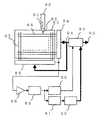
特許文献1に示した従来技術の入力装置を図面を用いて説明する。図7は、特許文献1に示した従来技術の入力装置を示す構成図である。
図7において、80は指示器であるペン、81は押しボタン、82は発信導体、83は座標盤、84はY軸用マルチプレクサ、85はY軸用センサー導体、86はX軸用マルチプレクサ、87はX軸用センサー導体、88は増幅器、89はバンドパスフィルタ、90はカウンタ、91はAC/DCコンバータ、92はA/Dコンバータ、93はCPU、94は制御信号、95は座標データ出力である。
A conventional input device disclosed in
In FIG. 7, 80 is an indicator pen, 81 is a push button, 82 is a transmission conductor, 83 is a coordinate board, 84 is a multiplexer for Y axis, 85 is a sensor conductor for Y axis, 86 is a multiplexer for X axis, 87 Is an X-axis sensor conductor, 88 is an amplifier, 89 is a band pass filter, 90 is a counter, 91 is an AC / DC converter, 92 is an A / D converter, 93 is a CPU, 94 is a control signal, and 95 is a coordinate data output. is there.
特許文献1に示した従来技術の入力装置は、ペン80の内部に正弦波や矩形波などの電気信号を発生する図示しない電気信号発生回路があり、ペン80の先端部のスタイラスが発信導体82となって、そこから周辺に電気信号を放射する。座標盤83の内部には信号検出手段として図示するような格子状のX軸用センサー導体87およびY軸用センサー導体85が配設してある。
ペン80の発信導体82とX軸用センサー導体87、Y軸用センサー導体85との間には静電容量(結合容量)が存在し、発信導体82からの電気信号がそれぞれ伝わる。発信導体82に近いX軸用センサー導体87、Y軸用センサー導体85は、結合容量が大きいため電気信号も強く伝わる。
X軸用マルチプレクサ86およびY軸用マルチプレクサ84がX軸用センサー導体87、Y軸用センサー導体85をCPU93の制御により順次切り換えてそれらが検出した各電気信号を増幅器88へ順次印加する。
バンドパスフィルタ89は、必要周波数帯域以外のノイズ成分を除去する。バンドパスフィルタ89の出力信号は、AC/DCコンバータ91へ印加され、DCレベルに変換され、さらにA/Dコンバータ92に印加され数値化される。CPU93はこの数値化された、X軸用センサー導体87、Y軸用センサー導体85の電気信号レベル(信号の強さ)か
ら数値計算またはあらかじめ用意してある表によりペン80の先端の座標盤83上での座標を特定する。
The prior art input device disclosed in
Capacitance (coupling capacitance) exists between the
The
The
しかしながら、特許文献1に示した従来技術の入力装置は、電気信号を発生する回路を内部に有した特殊なペンが必要であり、このペンを利用しないと入力装置を利用できないという問題があった。
すなわち、従来技術の入力装置を使用する際は、このペンを必ず携帯しなければならない。また、ペンには電気信号発生回路などを駆動するための電源となる電池などが必要であり、電池が消耗した場合、発信導体82からの電気信号の放射が弱くなるため、入力装置として動作が不安定になり、入力が正常に行われなくなってしまうという問題があった。特に、外出中など、交換用の電池を早急に用意できない環境での使用においては、その時点で入力装置が利用できなくなるために、深刻な問題であった。さらに、持ち運びながら使用する小型の携帯機器に従来技術の入力装置を搭載した場合、入力作業環境が移動するために、ペンを置き忘れてしまうこともあり、このような場合においても、入力そのものが全くできなくなるという問題もあった。
また、入力作業時にはペンを手で握る必要があるために、長時間の入力作業では疲労してしまうという問題があった。さらに、例えば、怪我などの事情でペンを握れない状況においては、入力作業ができないという問題もあった。
However, the input device of the prior art shown in
That is, when using a prior art input device, the pen must be carried. Further, the pen needs a battery as a power source for driving an electric signal generating circuit and the like. When the battery is exhausted, the electric signal radiation from the
Further, since it is necessary to hold the pen with the hand during the input operation, there is a problem that the input operation for a long time causes fatigue. In addition, for example, there is a problem that the input operation cannot be performed in a situation where the pen cannot be gripped due to circumstances such as injury.
本発明の目的は、上記課題を解決しようとするもので、耐久性、操作性の優れた入力装置を提供することにある。 An object of the present invention is to solve the above-described problems and to provide an input device having excellent durability and operability.
上記目的を達成するため、本発明の入力装置は下記に示す構造を採用する。 In order to achieve the above object, the input device of the present invention adopts the following structure.
信号検出手段を有し、信号検出手段と接触または近接した物体との間の静電容量結合の変化を利用して情報を入力する入力装置であって、
人体に信号を印加する信号印加手段を有し、
信号検出手段は、人体が信号検出手段に接触または近接した際に信号を検出し、
人体の動作に伴って生じる、人体と信号検出手段との間の信号の変化に基づいて情報を入力することを特徴とする。
An input device that has signal detection means and inputs information using a change in capacitive coupling between the signal detection means and an object that is in contact with or close to the signal detection means,
Having signal applying means for applying a signal to the human body;
The signal detection means detects a signal when a human body contacts or approaches the signal detection means,
Information is input based on a change in a signal between the human body and the signal detection means, which is caused by the movement of the human body.
信号印加手段は、特定の周波数の信号を生成する交流電源と、人体へ信号を印加する端子である印加電極と、印加電極への人体の接触を検出する接触検出手段とを有することを特徴とする。 The signal applying means includes an AC power source that generates a signal of a specific frequency, an application electrode that is a terminal that applies a signal to the human body, and a contact detection means that detects contact of the human body with the application electrode. To do.
信号検出手段は、人体からの信号を検出する端子である複数の透明電極と、信号に含まれる電流を検出電圧に変換する検出抵抗と、検出電圧を増幅する差動増幅器と、透明電極の接続を切り換えるスイッチとを有することを特徴とする。 The signal detection means includes a plurality of transparent electrodes that are terminals for detecting a signal from a human body, a detection resistor that converts a current included in the signal into a detection voltage, a differential amplifier that amplifies the detection voltage, and a connection between the transparent electrodes And a switch for switching between.
透明電極は、液晶表示装置の液晶駆動電極であることを特徴とする。 The transparent electrode is a liquid crystal drive electrode of a liquid crystal display device.
透明電極は、腕時計型機器の風防ガラスに配置したことを特徴とする。 The transparent electrode is arranged on a windshield of a wristwatch type device.
本発明の入力装置は、人体に信号を印加し、その印加された信号を検出することによっ
て入力を検出するものであり、指など人体の一部を指示器として使用ことができるため、情報の入力の際に特殊なペンや特別な指示器を使用する必要がないという効果がある。
従来技術で問題となっていた、指示器の電池切れや紛失の心配がなく、さらに、指示器を持つことによる疲労もなく、長時間の入力を行うことができるという効果があり、入力作業の操作性を格段に向上させることができる。
The input device of the present invention detects input by applying a signal to the human body and detecting the applied signal, and a part of the human body such as a finger can be used as an indicator. There is an effect that it is not necessary to use a special pen or a special indicator for input.
There is no worry about battery shortage or loss of the indicator, which has been a problem with the conventional technology, and there is no fatigue caused by holding the indicator. The operability can be greatly improved.
また、抵抗膜方式の指示位置検出装置のように、可動部を持つ必要がないから、耐久性を向上させることができる。 Further, unlike the resistance film type indication position detection device, since it is not necessary to have a movable part, durability can be improved.
さらに、人体の接触を検出する接触検出手段を設けたため、未使用時の電力を低減することができ、電池寿命を向上させることができる。 Furthermore, since the contact detection means for detecting the contact of the human body is provided, the power when not in use can be reduced, and the battery life can be improved.
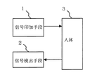
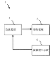
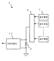
以下図面により本発明の実施の形態を詳述する。図1は、本発明の入力装置を示す構成図である。図2は、本発明の入力装置の信号印加手段を示す構成図である。図3は、本発明の入力装置の信号検出手段を示す構成図である。図4は、本発明の入力装置の第1の使用形態を示す模式図である。図5は、本発明の入力装置の第2の使用形態を示す模式図である。図6は、本発明の入力装置の接触検出手段を示す図であって、図6(a)は、接触検出手段の正面図であり、図6(b)は、接触検出手段の構成図である。 Hereinafter, embodiments of the present invention will be described in detail with reference to the drawings. FIG. 1 is a block diagram showing an input device of the present invention. FIG. 2 is a block diagram showing signal applying means of the input device of the present invention. FIG. 3 is a block diagram showing signal detection means of the input device of the present invention. FIG. 4 is a schematic diagram showing a first usage pattern of the input device of the present invention. FIG. 5 is a schematic diagram showing a second usage pattern of the input device of the present invention. 6A and 6B are diagrams showing the contact detection means of the input device of the present invention. FIG. 6A is a front view of the contact detection means, and FIG. 6B is a configuration diagram of the contact detection means. is there.
[構造説明:図1〜図6]
まず、本発明の入力装置の構成を図1から図6を用いて説明する。
図1において、1は信号印加手段、2は信号検出手段、3は人体である。
[Structure explanation: FIGS. 1 to 6]
First, the configuration of the input device of the present invention will be described with reference to FIGS.
In FIG. 1, 1 is a signal applying means, 2 is a signal detecting means, and 3 is a human body.
図2において、4は交流電源、5は印加電極、6は接触検出手段である。 In FIG. 2, 4 is an AC power source, 5 is an applied electrode, and 6 is a contact detection means.
図3において、7は透明電極、8はスイッチ、9は検出抵抗、10は差動増幅器である。透明電極7は複数設けている。
In FIG. 3, 7 is a transparent electrode, 8 is a switch, 9 is a detection resistor, and 10 is a differential amplifier. A plurality of
図4において、11は携帯情報機器、12は信号経路である。30は左手、31は右手である。 In FIG. 4, 11 is a portable information device, and 12 is a signal path. 30 is the left hand and 31 is the right hand.
図5において、13は腕時計型機器であり、例えば、腕時計である。
In FIG. 5,
図6において、14は第1の接触検出電極、15は第2の接触検出電極、16は接触検出抵抗である。33は人体の抵抗である。 In FIG. 6, 14 is a first contact detection electrode, 15 is a second contact detection electrode, and 16 is a contact detection resistor. 33 is the resistance of the human body.
なお、図1から図6において同一の構成には同一の番号を付与している。 1 to 6, the same number is assigned to the same configuration.
[原理説明:図1、図2、図3]
まずはじめに、本発明の入力装置の基本原理を図1、図2、図3を用いて説明する。
[Principle explanation: Fig.1, Fig.2, Fig.3]
First, the basic principle of the input device of the present invention will be described with reference to FIGS.
図1に示すように、本発明の入力装置は、信号印加手段1によって人体3に交流信号を印加し、その印加された信号を信号検出手段2によって検出することで入力を行うものである。
As shown in FIG. 1, the input device of the present invention performs input by applying an AC signal to a
図2に示すように、信号印加手段1は、交流電源4によって特定周波数の信号を発生し、印加電極5を通して人体3に信号を印加する。印加電極5は、絶縁体カバーで覆うことができる。これは、印加する信号が交流であるため、人体3が印加電極5に接触するか近接したときに発生する静電容量結合を通して信号が伝搬するためである。人体3と印加電
極5との近接距離は、おおよそ2mm程度である。もちろん、近接距離が大きくなるほど人体3に信号が印加されにくくなるので、この距離は小さい方が好ましい。
また、接触検出手段6は、印加電極5の近傍に配置され、人体3の接触の有無を検出する。これによって、人体3が接触していない場合、交流電源4を停止することができ、消費電力を効果的に低減することができる。
もちろん、人体3が接していても、交流電源4を停止することもできる。例えば、ある一定時間入力が行われない場合である。すなわち、一定時間入力が行われないとき20mSec間隔で交流電源4を停止し、一旦入力が始まったら2mSec間隔で停止させるというように、停止時間を切り換えることもできる。もちろん、交流電源4を停止させる間隔は、これに限定されず、自由に選択することができる。このように、間欠動作とすることで、常時交流電源4を常時動作させておく場合に比べ、消費電力を低減することができる。
As shown in FIG. 2, the
The contact detection means 6 is disposed in the vicinity of the
Of course, even if the
図3に示すように、信号検出手段2は、複数設けられた透明電極7によって、人体3からの信号を検出する。透明電極7は、絶縁体カバーで覆うことができる。これは、検出する信号が交流であるため、人体3が透明電極7に接触するか近接したときに発生する静電容量結合を通して信号が伝搬するためである。人体3と透明電極7との近接距離は、おおよそ1mm〜2mm程度である。もちろん、近接距離が小さくなるほど検出しやすくなるので、この距離は小さい方が好ましい。
スイッチ8は、透明電極7と検出抵抗9との接続を順次切り換える。スイッチ8には、図示しないが、透明電極7に接続する複数のスイッチ要素が設けてある。このスイッチ要素は、一般的な接点リレーや半導体スイッチなどを使用することができるが、スイッチングに要する抵抗、所謂オン抵抗は小さい方が好ましい。差動増幅器10は、検出抵抗9に現れる電圧を増幅する。差動増幅器10には市販のインプリメンテーションアンプを使用することができる。
As shown in FIG. 3, the
The
検出の手順は、スイッチ8のスイッチ要素を切り換えながら、それぞれの透明電極7に現れる信号を順次検出していく。信号印加手段1により人体3に信号が印加されているため、人体3に最も接近している透明電極7において、最も大きい振幅の信号が現れ、差動増幅器10の出力が最大となる。このようにして、指示位置を特定できる。
つまり、人体3の動作に伴って、人体3と信号検出手段2との間の信号が変化し、この変化に基づいて情報を入力するのである。
In the detection procedure, the signals appearing on the
That is, as the
[動作説明:図4、図5、図6]
次に、本発明の入力装置の動作を図4、図5、図6を用いて説明する。
[Description of operation: FIG. 4, FIG. 5, FIG. 6]
Next, the operation of the input device of the present invention will be described with reference to FIGS.
図4は、本発明の入力装置の第1の実施形態として、本発明の入力装置を携帯情報機器11に搭載した場合を模式的に示すものである。図4では、左手30で携帯情報機器11を掴み、右手31で入力を行う場合を示している。
図4に示すように、携帯情報機器11を保持する部分に印加電極5と接触検出手段6とを設ける。印加電極5より印加された信号は、左手30の親指から人体を経由して右手31の人差し指に伝わる。すなわち、図4に示す信号経路12を形成して、透明電極7に伝搬する。
指示した座標を検出する場合は、X方向、Y方向に交差するように透明電極7を配置する。一般に携帯情報機器11には、表示装置が組み込まれてある。例えば、液晶表示装置である。その液晶表示装置を駆動する液晶駆動電極は、X方向、Y方向に交差するように配置されているため、これと透明電極7とを共用することができる。
FIG. 4 schematically shows a case where the input device of the present invention is mounted on the portable information device 11 as the first embodiment of the input device of the present invention. FIG. 4 shows a case where the portable information device 11 is held with the
As shown in FIG. 4, the
When detecting the designated coordinates, the
検出の際は、スイッチ8のスイッチ要素を切り換えつつ、それぞれの透明電極7に現れる信号を順次検出していくが、もちろん、右手31で指示した座標は、1つでなくてもか
まわない。例えば、複数の座標からなる領域にアイコンなどの絵文字や記号を表示して、それをボタンを押すごとく複数回操作するようにしてもよい。
また、透明電極7の上で右手31の指を滑らせるなどして文字や記号をシンボルとして描いたとしても、スイッチ要素の切り換えを複数回行い、透明電極7に現れる信号を調べることで、描いたその文字や記号の入力が可能となる。つまり、「A」や「2」や「%」などの文字や記号を指で描くことにより、そのまま入力することもできるのである。
At the time of detection, the signals appearing on the respective
Even if characters or symbols are drawn as symbols by sliding the finger of the
図6は接触検出手段6を示す図である。図6(a)に示すように、接触検出手段6は、印加電極5と一体構造となるように配置される。接触検出手段6は、第1の接触検出電極14と第2の接触検出電極15とを有し、図6(b)に示すように、第1の接触検出電極14には直流の電圧Eを印加しておく。図6(b)に示す人体3は、例えば、親指である。
人体3は直流的には数百KΩ程度の抵抗と見なせるため、親指などで接触検出手段6を触れると、人体3の抵抗33と接触検出抵抗16とで直列抵抗回路が形成され、その直列抵抗比に応じた電圧Voutが第2の接触検出電極15から検出される。人体3が触れていない場合は、接触検出抵抗16によるプルダウンとなるのでVoutは0Vである。このようにして、接触の有無を検出することができる。
FIG. 6 is a diagram showing the contact detection means 6. As shown in FIG. 6A, the contact detection means 6 is arranged so as to be integrated with the
Since the
図6に示す接触検出手段6は、軽く人体を触れるだけで検出が可能なものである。しかし、接触検出手段6はこれに限定するものではない。例えば、機械的スイッチや感圧素子、導電ゴムなどを利用して接触検出手段6を構成しても良く、本発明の入力装置を搭載する機器の仕様や利用状況に応じて変更が可能である。 The contact detection means 6 shown in FIG. 6 can be detected simply by touching a human body. However, the contact detection means 6 is not limited to this. For example, the contact detection means 6 may be configured using a mechanical switch, a pressure sensitive element, a conductive rubber, or the like, and can be changed according to the specifications and usage status of a device on which the input device of the present invention is mounted. .
図5は本発明の入力装置の第2の実施形態として、本発明の入力装置を腕時型機器13に搭載した場合を模式的に示すものである。図5では、左手30の手首に腕時型機器13を装着し、右手31で入力を行う場合を示している。
図示はしないが、腕時型機器13の裏面に信号印加手段1を設けている。信号印加手段1によって印加された信号は、左手30の手首から人体を経由して右手31の人差し指に伝わる。すなわち、図5に示す信号経路12を形成して、腕時型機器13の風防ガラスに配置した透明電極7に伝搬し、指示された位置を検出することができる。
FIG. 5 schematically shows a case where the input device of the present invention is mounted on the arm-
Although not shown, the
腕時型機器13にはさまざまなアプリケーションが搭載されている。腕時型機器13が例えば、多機能な腕時計であるとすると、この腕時計のさまざまな機能、例えば、時刻修正やアラーム時刻の設定、クロノメータのスタートやストップ、機能メニューの選択などにおいて本発明の入力装置を利用することができる。これにより、ボタンや竜頭の操作を不要とし、タッチという直感的に分かりやすい動作で操作できるようになる。さらに、ボタンや竜頭が不要となったり、その数を減らすことができるため、腕時計としてのデザインの自由度を増すことができる。
図5では、説明のために透明電極7を円形で示したが、もちろん、その形状に限定されるものではない。腕時計の風防ガラス下に表示装置を設け、例えば、アイコンなどの絵文字や記号を表示して、それをボタンを押すごとく操作する場合においては、透明電極7は、その形状に合わせて設けることができる。
Various applications are mounted on the
In FIG. 5, the
本発明の入力装置は、人体に信号を印加し、その印加された信号を検出することによって入力を検出するものであり、指など人体の一部を指示器として使用ことができるため、情報の入力の際に特殊なペンや特別な指示器を使用する必要がなく、操作性を格段に向上させることができる。従来技術で問題となっていた、指示器の電池切れや紛失の心配が無く、さらに、指示器を持つことによる疲労もなく、長時間の入力を行うことができる。 The input device of the present invention detects input by applying a signal to the human body and detecting the applied signal, and a part of the human body such as a finger can be used as an indicator. There is no need to use a special pen or special indicator for input, and the operability can be greatly improved. There is no worry about battery shortage or loss of the indicator, which has been a problem in the prior art, and there is no fatigue caused by holding the indicator, and input can be performed for a long time.
また、抵抗膜方式の指示位置検出装置のように、可動部を持つ必要がないから、耐久性
を向上させることができる。
Further, unlike the resistance film type indication position detection device, since it is not necessary to have a movable part, durability can be improved.
また、人体の接触を検出する接触検出手段を設けたため、人体が接触していない場合、人体に信号を印加する交流電源を停止することができ、未使用時の消費電力を効果的に低減することができる。
さらに、ある一定時間入力が行われない場合は、人体への信号の印加を停止することができるため、間欠動作とすることができ、消費電力を低減することができる。
In addition, since the contact detection means for detecting the contact of the human body is provided, the AC power supply for applying a signal to the human body can be stopped when the human body is not in contact, and the power consumption when not in use is effectively reduced. be able to.
Furthermore, when input is not performed for a certain period of time, application of a signal to the human body can be stopped, so that an intermittent operation can be performed and power consumption can be reduced.
本発明の入力装置は、人体に電気的な信号を印加するが、その電気信号は、おおよそ800μA程度であって、人体に影響しないレベルのものであることは言うまでもない。 The input device of the present invention applies an electrical signal to the human body, and it goes without saying that the electrical signal is about 800 μA and does not affect the human body.
本発明の入力装置は、耐久性の求められるコンピュータや、情報端末、人体が掴むことができる機器、人体に装着することができる機器に適用することができる。特に限られた装置サイズで入力の操作性が重要とされる小型の携帯情報機器に好適である。 The input device of the present invention can be applied to a computer, an information terminal, a device that can be grasped by a human body, and a device that can be attached to a human body, which are required to have durability. It is particularly suitable for small portable information devices in which input operability is important with a limited device size.
1 信号印加手段
2 信号検出手段
3 人体
4 交流電源
5 印加電極
6 接触検出手段
7 透明電極
8 スイッチ
9 検出抵抗
10 差動増幅器
11 携帯情報機器
12 信号経路
13 腕時計
14 第1の接触検出電極
15 第2の接触検出電極
16 接触検出抵抗
30 左手
31 右手
33 人体の抵抗
80 ペン
81 押しボタン
82 発信導体
83 座標盤
84 Y軸用マルチプレクサ
85 Y軸用センサー導体
86 X軸用マルチプレクサ
87 X軸用センサー導体
88 増幅器
89 バンドパスフィルタ
90 カウンタ
91 AC/DCコンバータ
92 A/Dコンバータ
93 CPU
94 制御信号
95 座標データ出力
DESCRIPTION OF
94
Claims (5)
人体に信号を印加する信号印加手段を有し、
前記信号検出手段は、人体が前記信号検出手段に接触または近接した際に前記信号を検出し、
人体の動作に伴って生じる、人体と前記信号検出手段との間の前記信号の変化に基づいて情報を入力することを特徴とする入力装置。 An input device that has signal detection means and inputs information using a change in capacitive coupling between the signal detection means and an object that is in contact with or close to the signal detection means,
Having signal applying means for applying a signal to the human body;
The signal detection means detects the signal when a human body contacts or approaches the signal detection means,
An input device for inputting information on the basis of a change in the signal between the human body and the signal detection means, which is caused by the movement of the human body.
特定の周波数の前記信号を生成する交流電源と、
人体へ前記信号を印加する端子である印加電極と、
前記印加電極への人体の接触または近接を検出する接触検出手段とを有することを特徴とする請求項1に記載の入力装置。 The signal applying means includes
An AC power supply that generates the signal of a specific frequency;
An application electrode that is a terminal for applying the signal to the human body;
The input device according to claim 1, further comprising contact detection means for detecting contact or proximity of a human body to the application electrode.
人体からの前記信号を検出する端子である複数の透明電極と、
前記信号に含まれる電流を検出電圧に変換する検出抵抗と、
前記検出電圧を増幅する差動増幅器と、
前記透明電極の接続を切り換えるスイッチとを有することを特徴とする請求項1または2のいずれか1つに記載の入力装置。 The signal detection means includes
A plurality of transparent electrodes which are terminals for detecting the signal from the human body;
A detection resistor for converting a current included in the signal into a detection voltage;
A differential amplifier for amplifying the detection voltage;
The input device according to claim 1, further comprising a switch that switches connection of the transparent electrode.
Priority Applications (1)
| Application Number | Priority Date | Filing Date | Title |
|---|---|---|---|
| JP2004315228A JP2006127190A (en) | 2004-10-29 | 2004-10-29 | Input device |
Applications Claiming Priority (1)
| Application Number | Priority Date | Filing Date | Title |
|---|---|---|---|
| JP2004315228A JP2006127190A (en) | 2004-10-29 | 2004-10-29 | Input device |
Publications (1)
| Publication Number | Publication Date |
|---|---|
| JP2006127190A true JP2006127190A (en) | 2006-05-18 |
Family
ID=36721890
Family Applications (1)
| Application Number | Title | Priority Date | Filing Date |
|---|---|---|---|
| JP2004315228A Pending JP2006127190A (en) | 2004-10-29 | 2004-10-29 | Input device |
Country Status (1)
| Country | Link |
|---|---|
| JP (1) | JP2006127190A (en) |
Cited By (5)
| Publication number | Priority date | Publication date | Assignee | Title |
|---|---|---|---|---|
| EP1852056A1 (en) | 2006-05-01 | 2007-11-07 | Fujinon Corporation | Endoscope system |
| WO2010024028A1 (en) * | 2008-08-29 | 2010-03-04 | 日本電気株式会社 | Position information input device and position information input method |
| WO2013128981A1 (en) * | 2012-02-27 | 2013-09-06 | 国立大学法人九州大学 | Touch sensor-equipped mobile device and display device |
| JP2014530404A (en) * | 2011-09-13 | 2014-11-17 | 熊光 蔡 | Vision interface system |
| JP2019528504A (en) * | 2016-10-27 | 2019-10-10 | サーク・コーポレーション | Finger tracking on input devices with proximity sensing |
-
2004
- 2004-10-29 JP JP2004315228A patent/JP2006127190A/en active Pending
Cited By (8)
| Publication number | Priority date | Publication date | Assignee | Title |
|---|---|---|---|---|
| EP1852056A1 (en) | 2006-05-01 | 2007-11-07 | Fujinon Corporation | Endoscope system |
| WO2010024028A1 (en) * | 2008-08-29 | 2010-03-04 | 日本電気株式会社 | Position information input device and position information input method |
| JP5375828B2 (en) * | 2008-08-29 | 2013-12-25 | 日本電気株式会社 | POSITION INFORMATION INPUT DEVICE AND POSITION INFORMATION INPUT METHOD |
| US8743079B2 (en) | 2008-08-29 | 2014-06-03 | Nec Corporation | Position information input device and position information input method |
| JP2014530404A (en) * | 2011-09-13 | 2014-11-17 | 熊光 蔡 | Vision interface system |
| US9335849B2 (en) | 2011-09-13 | 2016-05-10 | Hsiung-Kuang Tsai | Visual interface system |
| WO2013128981A1 (en) * | 2012-02-27 | 2013-09-06 | 国立大学法人九州大学 | Touch sensor-equipped mobile device and display device |
| JP2019528504A (en) * | 2016-10-27 | 2019-10-10 | サーク・コーポレーション | Finger tracking on input devices with proximity sensing |
Similar Documents
| Publication | Publication Date | Title |
|---|---|---|
| CN106462263B (en) | Position indicator, position detection device, and input control method for position detection device | |
| JP5995473B2 (en) | Capacitance sensor control circuit and electronic equipment using it | |
| US9024893B2 (en) | Controlling system and a controlling method of a touch panel, and a stylus pen for applying to the touch panel | |
| US8531419B2 (en) | Information processing apparatus, operation input method, and sensing device | |
| KR101474733B1 (en) | A capacitive touch screen for integrated of fingerprint recognition having improved pattern structure | |
| JP2010067117A (en) | Touch panel device | |
| JP5485154B2 (en) | Input devices, especially computer mice | |
| TW201510804A (en) | Control method for touch panel | |
| KR20130049453A (en) | Touch sensing apparatus and operating method thereof | |
| JPH08137607A (en) | Coordinate input device | |
| JP2013025584A (en) | Information processor | |
| KR20110138743A (en) | Mobile device having back and side touch pad | |
| JP2005084982A (en) | Electrostatic capacitance type touch panel device | |
| TWI515632B (en) | Touch-and-play input device and operating method thereof | |
| KR20200116655A (en) | Touch input device | |
| JP2013235359A (en) | Information processor and input device | |
| JP5147821B2 (en) | Input device | |
| JP2006127190A (en) | Input device | |
| KR100960942B1 (en) | Complex-type input device with touch sensing features | |
| JP2013069165A (en) | Portable terminal device, image control method, and image control program | |
| US20150370352A1 (en) | Active stylus pen, data input system and control method of active stylus pen | |
| KR20110029246A (en) | Complex-type input device with touch sensing features | |
| CN113190130B (en) | Touch-control type active pen | |
| CN111381735B (en) | Button-like sheet and touch panel | |
| US20170060277A1 (en) | Magnetic switch assembly and stylus having the same |


