CN219283281U - Fill lamp plate subassembly of electric pile and fill electric pile - Google Patents
Fill lamp plate subassembly of electric pile and fill electric pile Download PDFInfo
- Publication number
- CN219283281U CN219283281U CN202320155136.4U CN202320155136U CN219283281U CN 219283281 U CN219283281 U CN 219283281U CN 202320155136 U CN202320155136 U CN 202320155136U CN 219283281 U CN219283281 U CN 219283281U
- Authority
- CN
- China
- Prior art keywords
- lamp panel
- hole
- light
- side wall
- light guide
- Prior art date
- Legal status (The legal status is an assumption and is not a legal conclusion. Google has not performed a legal analysis and makes no representation as to the accuracy of the status listed.)
- Active
Links
Images
Classifications
-
- Y—GENERAL TAGGING OF NEW TECHNOLOGICAL DEVELOPMENTS; GENERAL TAGGING OF CROSS-SECTIONAL TECHNOLOGIES SPANNING OVER SEVERAL SECTIONS OF THE IPC; TECHNICAL SUBJECTS COVERED BY FORMER USPC CROSS-REFERENCE ART COLLECTIONS [XRACs] AND DIGESTS
- Y02—TECHNOLOGIES OR APPLICATIONS FOR MITIGATION OR ADAPTATION AGAINST CLIMATE CHANGE
- Y02T—CLIMATE CHANGE MITIGATION TECHNOLOGIES RELATED TO TRANSPORTATION
- Y02T10/00—Road transport of goods or passengers
- Y02T10/60—Other road transportation technologies with climate change mitigation effect
- Y02T10/70—Energy storage systems for electromobility, e.g. batteries
-
- Y—GENERAL TAGGING OF NEW TECHNOLOGICAL DEVELOPMENTS; GENERAL TAGGING OF CROSS-SECTIONAL TECHNOLOGIES SPANNING OVER SEVERAL SECTIONS OF THE IPC; TECHNICAL SUBJECTS COVERED BY FORMER USPC CROSS-REFERENCE ART COLLECTIONS [XRACs] AND DIGESTS
- Y02—TECHNOLOGIES OR APPLICATIONS FOR MITIGATION OR ADAPTATION AGAINST CLIMATE CHANGE
- Y02T—CLIMATE CHANGE MITIGATION TECHNOLOGIES RELATED TO TRANSPORTATION
- Y02T10/00—Road transport of goods or passengers
- Y02T10/60—Other road transportation technologies with climate change mitigation effect
- Y02T10/7072—Electromobility specific charging systems or methods for batteries, ultracapacitors, supercapacitors or double-layer capacitors
-
- Y—GENERAL TAGGING OF NEW TECHNOLOGICAL DEVELOPMENTS; GENERAL TAGGING OF CROSS-SECTIONAL TECHNOLOGIES SPANNING OVER SEVERAL SECTIONS OF THE IPC; TECHNICAL SUBJECTS COVERED BY FORMER USPC CROSS-REFERENCE ART COLLECTIONS [XRACs] AND DIGESTS
- Y02—TECHNOLOGIES OR APPLICATIONS FOR MITIGATION OR ADAPTATION AGAINST CLIMATE CHANGE
- Y02T—CLIMATE CHANGE MITIGATION TECHNOLOGIES RELATED TO TRANSPORTATION
- Y02T90/00—Enabling technologies or technologies with a potential or indirect contribution to GHG emissions mitigation
- Y02T90/10—Technologies relating to charging of electric vehicles
- Y02T90/12—Electric charging stations
Landscapes
- Non-Portable Lighting Devices Or Systems Thereof (AREA)
Abstract
The application discloses fill lamp plate subassembly of electric pile and fill electric pile belongs to the technical field that charges. The lamp plate subassembly of charging stake includes: the LED lamp comprises a lamp panel shell, a lamp panel structure and a light guide plate, wherein the lamp panel shell is provided with an installation cavity, and the outer side wall of the installation cavity is provided with a first through hole; the lamp panel structure is arranged on the inner side wall of the mounting cavity, and the light-emitting area of the lamp panel structure is opposite to the first through hole; the light guide plate is arranged on the outer side wall of the mounting cavity and seals the first through hole. According to the lamp panel assembly of the charging pile, the first through hole of the outer side wall of the installation cavity is sealed through the light guide plate, so that rainwater cannot enter from the first through hole on the side face of the installation cavity, the environment in the installation cavity can be relatively dry, and the circuit structure on the lamp panel structure is protected.
Description
Technical Field
The application belongs to the technical field of charging, and especially relates to a lamp plate assembly of charging pile and charging pile.
Background
The signal indication on the charging pile is realized through the lamp plate assembly, in order to prevent the lamp plate assembly from damaging because of rainwater etc., in the related art, the lamp plate assembly is generally all installed inside the rack of charging pile, at night or in the remote position, the car owner is difficult to see the indication state of lamp, influences charging use efficiency and car owner's experience of charging pile, and installs the difficult maintenance of lamp plate assembly in inside, only can maintain by opening whole charging pile, but this can influence the waterproof dustproof performance of complete machine again.
Disclosure of Invention
The present application aims to solve at least one of the technical problems existing in the prior art. Therefore, the application provides a lamp plate assembly of charging pile for prevent that rainwater from getting into lamp plate assembly, lead to its damage.
In a first aspect, the present application provides a lamp panel assembly of a charging pile, comprising:
the lamp panel shell is provided with an installation cavity, and the outer side wall of the installation cavity is provided with a first through hole;
the lamp panel structure is arranged on the inner side wall of the mounting cavity, and the light-emitting area of the lamp panel structure is opposite to the first through hole;
the light guide plate is arranged on the outer side wall of the mounting cavity and seals the first through hole.
According to the lamp panel assembly of the charging pile, which is provided by the embodiment of the application, the lamp panel structure is internally provided with the mounting cavity, and the top of the mounting cavity is of a closed structure, so that rainwater cannot enter from the top of the mounting cavity; furthermore, the first through hole of the outer side wall of the mounting cavity is sealed through the light guide plate, so that rainwater cannot enter from the first through hole on the side surface of the mounting cavity, the environment in the mounting cavity can be relatively dry, and the circuit structure on the lamp plate structure is protected.
According to one embodiment of the application, the light guide plate comprises a light guide area and sealing areas located on two sides of the light guide area, the sealing areas are connected with the outer side wall of the mounting cavity, and the light guide area is opposite to the first through hole.
According to one embodiment of the application, the sealing area is provided with a first sealing strip, which is sandwiched between the light guide plate and the outer side wall of the mounting cavity.
According to one embodiment of the application, the sealing area is provided with a connecting structure, and the light guide plate is connected with the outer side wall of the mounting cavity through the connecting structure.
According to one embodiment of the application, the sealing area overlaps the inner surface of the outer side wall of the mounting cavity.
According to one embodiment of the present application, the light guiding area protrudes outwards corresponding to the sealing area, the light guiding plate is mounted on the inner surface of the outer side wall of the mounting cavity, and the light guiding area is embedded in the first through hole.
According to one embodiment of the application, the bottom wall of the installation cavity is provided with a water leakage hole.
According to one embodiment of the application, the inner side wall of the installation cavity is provided with a second through hole, and the first through hole and the second through hole are higher than the bottom wall of the installation cavity so as to form a water guide groove at the lower part of the installation cavity.
According to one embodiment of the present application, the second through hole is larger than the first through hole.
According to an embodiment of the application, the lamp panel structure is provided with a baffle protruding outwards, the baffle is opposite to the first through hole, and two sides of the baffle are respectively provided with a light-emitting area of the lamp panel structure.
According to one embodiment of the application, the lamp panel structure comprises a mounting plate and a lamp panel, wherein the mounting plate is mounted on the inner side wall of the mounting cavity; the lamp panel is arranged on the mounting plate and is opposite to the first through hole.
According to one embodiment of the application, a second sealing strip is clamped between the lamp panel structure and the inner side wall of the lamp panel shell.
In a second aspect, the present application provides a charging pile comprising:
the cabinet and the lamp panel assembly according to any one of the above embodiments, wherein the lamp panel assembly is mounted outside the cabinet.
According to the charging pile, through arranging the lamp panel assembly outside the cabinet, the lamp panel assembly is relatively separated from the cabinet, when the lamp panel assembly is overhauled, the lamp panel assembly can be overhauled only by detaching the lamp panel assembly from the outer surface of the inner side wall of the mounting cavity, the cabinet is not required to be opened, the light guide area of the light guide plate of the lamp panel assembly can be independently planned, the design of the light guide area is long enough or large enough, for example, the light guide area can be designed into a strip shape, and a user can clearly perceive the display light of the light guide area in a place far away from the cabinet.
Additional aspects and advantages of the application will be set forth in part in the description which follows, and in part will be obvious from the description, or may be learned by practice of the application.
Drawings
The foregoing and/or additional aspects and advantages of the present application will become apparent and readily appreciated from the following description of the embodiments, taken in conjunction with the accompanying drawings, wherein:
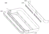
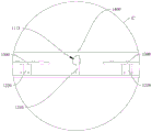
fig. 1 is a schematic structural diagram of a lamp panel assembly of a charging pile according to an embodiment of the present disclosure;
FIG. 2 is an enlarged view of a portion of FIG. 1 at A;
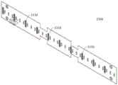
FIG. 3 is one of the structural schematic diagrams of the mounting plate provided in the embodiments of the present application;
FIG. 4 is a second schematic structural view of a mounting plate according to an embodiment of the present disclosure;
FIG. 5 is a third schematic structural view of a mounting plate according to an embodiment of the present disclosure;
fig. 6 is a schematic structural diagram of a lamp panel according to an embodiment of the present disclosure;
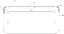
FIG. 7 is a second schematic diagram of a lamp panel assembly of a charging post according to an embodiment of the present disclosure;
FIG. 8 is a partial enlarged view at B in FIG. 7;
FIG. 9 is an enlarged view of a portion of FIG. 7 at C;
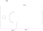
fig. 10 is a schematic structural diagram of a light guide plate according to an embodiment of the present disclosure;
FIG. 11 is a second schematic structural view of a light guide plate according to an embodiment of the present disclosure;
FIG. 12 is a third schematic structural view of a light guide plate according to an embodiment of the present disclosure;
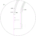
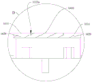
FIG. 13 is a third schematic view of a light panel assembly of a charging post according to an embodiment of the present disclosure;
fig. 14 is a partial enlarged view at D in fig. 13;
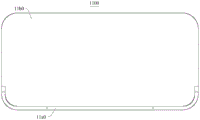
fig. 15 is a schematic structural diagram of a lamp panel shell according to an embodiment of the present disclosure;
FIG. 16 is a second schematic view of a lamp panel shell according to an embodiment of the present disclosure;
FIG. 17 is a third schematic view of a lamp panel shell according to an embodiment of the present disclosure;
fig. 18 is a schematic structural view of a charging pile according to an embodiment of the present disclosure.
Reference numerals:
a lamp panel assembly 1000;
the lamp panel case 1100 includes a housing area 11a0, a mounting chamber 1110, an outer sidewall 1111, a first through hole 1111a, an inner sidewall 1112, a second through hole 1112a, a water leakage hole 1113, a water guide 1114, and a fixing area 11b0;
a lamp plate 1300, a light emitting unit 1310;
a light guide plate 1400, a light guide region 1410, and a sealing region 1420;
and a cabinet 2000.
Detailed Description
Embodiments of the present application are described in detail below, examples of which are illustrated in the accompanying drawings, wherein the same or similar reference numerals refer to the same or similar elements or elements having the same or similar functions throughout. The embodiments described below by referring to the drawings are exemplary only for the purpose of explaining the present application and are not to be construed as limiting the present application.
The following describes a light panel assembly 1000 of a charging pile and the charging pile according to an embodiment of the present application with reference to fig. 1 to 18.
As shown in fig. 1, 2 and 6, the lamp panel assembly 1000 of the charging pile includes a lamp panel housing 1100, a lamp panel structure and a light guide plate 1400.
As shown in fig. 1 and 2, the lamp panel housing 1100 has a mounting cavity 1110, an outer side wall 1111 of the mounting cavity 1110 has a first through hole 1111a, and the outer side wall 1111 of the mounting cavity 1110 may be an outer wall of the mounting cavity 1110 facing away from a wall or a column after the charging pile is mounted on the wall or the column.
The lamp panel structure is mounted on the inner sidewall 1112 of the mounting cavity 1110, and the light emitting area of the lamp panel structure is opposite to the first through hole 1111a.
As shown in fig. 1 and 2, the lamp panel structure includes a mounting plate 1200 and a lamp panel 1300.
The mounting plate 1200 is mounted on the inner side wall 1112 of the mounting cavity 1110, the inner side wall 1112 of the mounting cavity 1110 is on the same side as the outer side wall 1111 of the mounting cavity 1110, and the inner side wall 1112 of the mounting cavity 1110 may be the inner wall of the mounting cavity 1110 facing away from the wall or the column after the charging pile is mounted on the wall or the column.
The lamp plate 1300 is mounted on the mounting plate 1200 and is opposite to the first through hole 1111a.
The lamp plate 1300 includes at least one circuit board and a plurality of light emitting units 1310, wherein the plurality of light emitting units 1310 can be directly opposite to the first through holes 1111a as light emitting areas of the lamp plate 1300, and the plurality of light emitting units 1310 are all mounted on the circuit board and electrically connected with the circuit board.
In actual implementation, according to the actual charging condition of the user, some light emitting units 1310 may be selected by the plurality of light emitting units 1310 to emit specific light, for example, when charging is in progress, some light emitting units 1310 emit green light, and when charging is completed, another part of light emitting units 1310 emit red light. Alternatively, the same light emitting unit 1310 may emit light of a plurality of colors according to instructions, green light when charging is being performed, and red light when charging is completed.
As shown in fig. 6, the light emitting unit 1310 may be an LED lamp bead, or may be another electroluminescent body.
Of course, the lamp panel structure may also include lamp panel 1300.
The light emitting region of the lamp plate 1300 may be opposite to the first through hole 1111a, and may be mounted on an inner sidewall 1112 (not shown in the drawings) of the mounting cavity 1110 through a side of the lamp plate 1300 facing away from the light emitting region.
As shown in fig. 1 and 2, the light guide plate 1400 is mounted on the outer sidewall 1111 of the mounting cavity 1110 and closes the first through hole 1111a, and all or part of the light guide plate 1400 should be made of a light-transmitting material, such as a light-transmitting plastic, and also such as tempered glass.
According to the lamp panel assembly 1000 of the charging pile provided by the embodiment of the application, the lamp panel 1300 is arranged in the installation cavity 1110, and the top of the installation cavity 1110 is of a closed structure, so that rainwater cannot enter from the top of the installation cavity 1110; in addition, the light guide plate 1400 seals the first through hole 1111a of the outer side wall 1111 of the mounting cavity 1110, so that rainwater cannot enter from the first through hole 1111a on the side of the mounting cavity 1110, and thus the environment in the mounting cavity 1110 is relatively dry, and the circuit structure on the lamp panel 1300 is protected.
In some embodiments, as shown in fig. 1-5, 7 and 9, the lamp panel structure is provided with a baffle 1210 protruding outwards, the baffle 1210 is opposite to the first through hole 1111a, and two sides of the baffle 1210 are respectively provided with a light emitting area of the lamp panel structure.
If the colors of the light emitted by the light emitting areas at two sides of the baffle 1210 are different, there is an influence of mutually light, and the application can reduce the influence by separating the light emitting areas at two sides of the baffle 1210, so that the user can better identify.
In some examples, as shown in fig. 1-5 and 9, the lamp plate structure includes a mounting plate 1200 and a lamp plate 1300, the mounting plate 1200 being mounted to an inner sidewall 1112 of the mounting cavity 1110; the lamp plate 1300 is mounted on the mounting plate 1200, and the light emitting areas of the lamp plate 1300 are distributed on two sides of the baffle 1210 and are opposite to the first through holes 1111a.
In actual implementation, as shown in fig. 9, a certain gap may be formed between the end of the baffle 1210 facing away from the light plate 1300 and the light guide plate 1400, and of course, the fitting of the end of the baffle 1210 facing away from the light plate 1300 and the light guide plate 1400 is also allowed.
In actual implementation, as shown in fig. 3-5 and 9, mounting plate 1200 is coupled to lamp plate 1300 via coupling posts 1220.
Wherein, the connecting post 1220 may have a threaded hole, the lamp plate 1300 is provided with a first mounting hole corresponding to the threaded hole, when assembling, the end of the connecting post 1220 deviating from the mounting plate 1200 is abutted against the portion of the first mounting hole where the lamp plate 1300 is located, and then connected with the threaded hole through a screw, and is pressed against the portion of the first mounting hole where the lamp plate 1300 is located.
Alternatively, the connection post 1220 may have external threads, and the lamp plate 1300 is provided with a first mounting hole corresponding to the connection post 1220, and when assembling, the first mounting hole of the lamp plate 1300 is sleeved on the connection post 1220, and then connected with the external threads through a nut, and is pressed against the part of the first mounting hole where the lamp plate 1300 is located.
In some embodiments, as shown in fig. 1-2 and 7-12, the light guide plate 1400 includes a light guide region 1410 and sealing regions 1420 located at both sides of the light guide region 1410, the sealing regions 1420 are connected to the outer side wall 1111 of the mounting cavity 1110, and the light guide region 1410 is opposite to the first through hole 1111a.
The light guiding area 1410 should be made of a light-transmitting material so that the light emitted from the light panel 1300 can be transmitted and identified by a user, and the sealing area 1420 should have a certain connection strength.
The light guiding area 1410 and the sealing area 1420 may be made of the same material, such as a polycarbonate plate, or may be made of different materials, such as a polycarbonate plate for the light guiding area 1410 and an alloy plate for the sealing area 1420, which is not limited in this embodiment.
The light guiding region 1410 and the sealing region 1420 may be integrally formed or separately connected, which is not limited in this embodiment.
As shown in fig. 1, 2 and 10, the sealing area 1420 is connected to the outer side wall 1111 of the mounting cavity 1110 either indirectly or directly.
For example, the sealing region 1420 of the light guide plate 1400 may be indirectly connected to the outer sidewall 1111 of the installation cavity 1110 by sandwiching a first sealing strip (not shown in the drawings).
By such design, rainwater can be prevented from entering between the light guide plate 1400 and the outer side wall 1111 of the installation cavity 1110, and the sealing effect of the light guide plate 1400 on the installation cavity 1110 is improved.
For another example, the sealing region 1420 of the light guide plate 1400 may directly overlap the inner surface of the outer sidewall 1111 of the mounting cavity 1110.
In actual implementation, as shown in fig. 1, 7 and 8, the sealing region 1420 of the light guide plate 1400 may be detachably connected with the outer sidewall 1111 of the installation cavity 1110 by a connection structure.
The connection structure may be a bolt and a nut, and the bolt sequentially passes through the sealing region 1420 of the light guide plate 1400, the outer sidewall 1111 of the installation cavity 1110, and is screwed with the nut; the connection structure may also be a screw that passes through the sealing region 1420 of the light guide plate 1400 and is screwed with the outer sidewall 1111 of the mounting cavity 1110.
In some embodiments, as shown in fig. 7 and 9, the bottom wall of the installation cavity 1110 is provided with a water leakage hole 1113, and the water leakage hole 1113 can be communicated with the external environment, so that even if the sealing effect of the light guide plate 1400 on the installation cavity 1110 is weakened in an extreme case, rainwater entering the installation cavity 1110 can leave from the water leakage hole 1113 as far as possible, so that the environment in the installation cavity 1110 is relatively dry, and the circuit structure on the lamp panel 1300 is protected.
In some examples, as shown in fig. 1 and 2, the inner sidewall 1112 of the mounting cavity 1110 is provided with a second through hole 1112a, such that the mounting plate 1200 of the lamp panel structure can be mounted to the outer surface of the inner sidewall 1112 of the mounting cavity 1110 and the second through hole 1112a is closed while the lamp panel 1300 of the lamp panel structure is built into the mounting cavity 1110.
In this design, compared with the mounting board 1200 being inserted from the first through hole 1111a and mounted on the inner sidewall 1112 of the mounting cavity 1110, the mounting process is more convenient, and the size of the first through hole 1111a is reduced, i.e. the size of the first through hole 1111a is only required to be equal to the size of the light emitting units 1310 arranged on the lamp panel 1300, and no corresponding size of the mounting board 1200 is required.
In practical implementation, the second through hole 1112a is larger than the first through hole 1111a, and the second through hole 1112a may be opposite to the first through hole 1111a, so that when the mounting board 1200 of the lamp panel structure is mounted on the inner sidewall 1112 of the mounting cavity 1110 from the second through hole 1112a, the light emitting area of the lamp panel 1300 of the lamp panel structure is opposite to the first through hole 1111a.
As shown in fig. 1, 2 and 7, the first through hole 1111a and the second through hole 1112a are higher than the bottom wall of the installation cavity 1110, a water guide groove 1114 is formed between the inner side wall 1112 of the installation cavity 1110 and the outer side wall 1111 of the installation cavity 1110, and the water guide groove 1114 is disposed at the lower portion of the installation cavity 1110, and the water leakage hole 1113 is located at the bottom wall of the water guide groove 1114.
In some embodiments, the bottom wall of the water guide 1114 is an inclined structure, and the water leakage hole 1113 is located at the lowest point of the bottom wall of the water guide 1114. Thus, the rainwater entering the installation cavity 1110 can be entirely led out from the water leakage hole 1113 by the drainage action of the water guide 1114.
As shown in fig. 1, 2 and 8, the mounting plate 1200 of the lamp panel structure can be mounted to the outer surface of the inner sidewall 1112 of the mounting cavity 1110 by a connector.
In practice, the connector may be a stud secured to the outer surface of the inner sidewall 1112 of the mounting cavity 1110 and having a hole thereon for mating with the stud, and a nut threadably coupled to the stud and abutting the mounting plate 1200.
The number of the studs is four, and the four studs are respectively arranged at four corners of the outer surface of the inner side wall 1112 of the mounting cavity 1110.
In some examples, a second seal may be interposed between the mounting plate 1200 of the lamp panel structure and the inner side wall 1112 of the mounting cavity 1110, such that rain water may be prevented from entering between the mounting plate 1200 and the inner side wall 1112 of the mounting cavity 1110, improving the sealing effect of the mounting plate 1200 to the mounting cavity 1110 (not shown in the figures).
For the light guide plate 1400 mounted on the outer side wall 1111 of the mounting cavity 1110, the following embodiments will be specifically described from two different implementation angles
1. As shown in fig. 1, 2, 13 and 14, the light guide region 1410 protrudes outward corresponding to the sealing region 1420, the light guide plate 1400 is mounted on the inner surface of the outer sidewall 1111 of the mounting cavity 1110, and the light guide region 1410 is embedded in the first through hole 1111a.
In this embodiment, rainwater enters the first through hole 1111a only by passing through the portion of the light guide region 1410 protruding from the sealing region 1420 and the wall of the first through hole 1111a, and then passing through the sealing region 1420 and the inner surface of the outer side wall 1111 of the installation cavity 1110.
The design improves the difficulty of rainwater entering the first through hole 1111a, and further ensures that the environment in the installation cavity 1110 is relatively dry, so that the circuit structure on the lamp panel 1300 is protected.
In actual implementation, as shown in fig. 14, a portion of the light guiding region 1410 protruding outwards from the sealing region 1420 may be in interference fit with the hole wall of the first through hole 1111a, or may be in clearance fit; the sealing area 1420 may be directly abutted against the inner surface of the outer side wall 1111 of the mounting cavity 1110, and the sealing area 1420 may be indirectly abutted against the inner surface of the outer side wall 1111 of the mounting cavity 1110 by the first sealing strip.
In addition, the portion of the light guiding region 1410 protruding outward from the sealing region 1420 may be equal to the wall thickness of the hole wall of the first through hole 1111a, or may be smaller or larger than the wall thickness of the hole wall of the first through hole 1111a, which is not limited in this embodiment.
2. Light guiding region 1410 is mounted to an outer surface (not shown in the drawings) of outer sidewall 1111 of mounting cavity 1110.
In this embodiment, rainwater can enter the first through hole 1111a only through the sealing region 1420 and the outer surface of the outer side wall 1111 of the installation cavity 1110.
The advantage of such a design is that the light guide plate 1400 is conveniently mounted with the outer surface of the outer sidewall 1111 of the mounting cavity 1110.
The actual assembly process of one embodiment of the present application is described below.
First, as shown in fig. 1, a lamp panel 1300 of a lamp panel structure is mounted on a mounting plate 1200 of the lamp panel structure by screws.
Next, as shown in fig. 2 and 14, the light guide plate 1400 is put in from the second through hole 1112a, and the first sealing strip is located between the sealing area 1420 of the light guide plate 1400 and the inner surface of the outer side wall 1111 of the mounting cavity 1110, and the portion of the light guide area 1410 protruding outwards from the sealing area 1420 is engaged with the wall of the first through hole 1111a.
Then, as shown in fig. 8, the light guide plate 1400 is mounted on the outer sidewall 1111 of the mounting cavity 1110 by sequentially passing through the sealing region 1420 of the light guide plate 1400 and the outer sidewall 1111 of the mounting cavity 1110 with bolts and screw-coupling with nuts.
Then, as shown in fig. 1, 2 and 8, the hole of the mounting plate 1200 of the lamp panel structure is engaged with the stud of the outer surface of the inner sidewall 1112 of the mounting cavity 1110 and the second through hole 1112a is closed, and at the same time, the second sealing strip is interposed between the mounting plate 1200 of the lamp panel structure and the inner sidewall 1112 of the mounting cavity 1110.
Finally, a nut is mounted on the stud and abuts against the mounting plate 1200 of the lamp panel structure.
The embodiment of the application also provides a charging pile, which comprises: and a cabinet 2000.
As shown in fig. 18, a lamp panel assembly 1000 is installed outside the cabinet 2000.
In the related art, the lamp panel assembly 1000 is integrated in the cabinet 2000 and transmits light outwards through the corresponding area of the display screen of the cabinet 2000, on one hand, the size of the display screen of the cabinet 2000 is limited, and the light transmission area of the display screen is limited, so that a user can only perceive the display light of the display screen of the cabinet 2000 when approaching the cabinet 2000 at night or at a far distance, on the other hand, the lamp panel assembly 1000 is integrated in the cabinet 2000, so that the internal usage space of the cabinet 2000 is occupied, the internal circuit arrangement of the cabinet 2000 is complicated, and once the lamp panel assembly 1000 needs to be overhauled, the cabinet 2000 can be maintained and replaced only by opening the cabinet 2000 first, and the process is very inconvenient.
As shown in fig. 1, 2 and 18, the lamp panel assembly 1000 is disposed outside the cabinet 2000, so that the lamp panel assembly 1000 is relatively separated from the cabinet 2000, and when the lamp panel assembly 1000 is overhauled, the mounting plate 1200 is only required to be detached from the outer surface of the inner side wall 1112 of the mounting cavity 1110, so that overhauling can be realized without opening the cabinet 2000.
Furthermore, the light guiding area 1410 of the light guiding plate 1400 of the light panel assembly 1000 can be designed to be long enough or large enough, for example, the light guiding area 1410 can be designed to be strip-shaped or block-shaped, so that the user can clearly perceive the display light of the light guiding area 1410 at a position far from the cabinet 2000.
The lamp panel assembly 1000 may be disposed on a top or side wall of the cabinet 2000, and the lamp panel housing 1100 of the lamp panel assembly 1000 is fixedly mounted to the cabinet 2000.
In actual implementation, as shown in fig. 15-18, the lamp panel case 1100 has a receiving area 11a0 and a fixing area 11b0, the receiving area 11a0 is disposed above the fixing area 11b0, and the receiving area 11a0 has a mounting cavity 1110, and the fixing area 11b0 is fixed on the top of the cabinet 2000 by a screw.
The terms first, second and the like in the description and in the claims, are used for distinguishing between similar objects and not necessarily for describing a particular sequential or chronological order. It is to be understood that the data so used may be interchanged, as appropriate, such that embodiments of the present application may be implemented in sequences other than those illustrated or described herein, and that the objects identified by "first," "second," etc. are generally of a type and not limited to the number of objects, e.g., the first object may be one or more. Furthermore, in the description and claims, "and/or" means at least one of the connected objects, and the character "/", generally means that the associated object is an "or" relationship.
In the description of the present application, it should be understood that the terms "length," "width," "thickness," "upper," "lower," "front," "rear," "left," "right," "vertical," "horizontal," "top," "bottom," "inner," "outer," and the like indicate an orientation or positional relationship based on that shown in the drawings, merely for convenience of description and to simplify the description, and do not indicate or imply that the devices or elements referred to must have a specific orientation, be configured and operated in a specific orientation, and thus should not be construed as limiting the present application.
In the description of the present application, "a first feature", "a second feature" may include one or more of the features.
In the description of the present application, the meaning of "plurality" is two or more.
In the description of this application, a first feature "above" or "below" a second feature may include both the first and second features being in direct contact, and may also include the first and second features not being in direct contact but being in contact by another feature therebetween.
In the description of this application, a first feature being "above," "over" and "on" a second feature includes the first feature being directly above and obliquely above the second feature, or simply indicating that the first feature is higher in level than the second feature.
In the description of the present specification, reference to the terms "one embodiment," "some embodiments," "illustrative embodiments," "examples," "specific examples," or "some examples," etc., means that a particular feature, structure, material, or characteristic described in connection with the embodiment or example is included in at least one embodiment or example of the present application. In this specification, schematic representations of the above terms do not necessarily refer to the same embodiments or examples. Furthermore, the particular features, structures, materials, or characteristics described may be combined in any suitable manner in any one or more embodiments or examples.
While embodiments of the present application have been shown and described, it will be understood by those of ordinary skill in the art that: many changes, modifications, substitutions and variations may be made to the embodiments without departing from the principles and spirit of the application, the scope of which is defined by the claims and their equivalents.
Claims (13)
1. A lamp panel assembly of a charging post, comprising:
the lamp panel shell is provided with an installation cavity, and the outer side wall of the installation cavity is provided with a first through hole;
the lamp panel structure is arranged on the inner side wall of the mounting cavity, and the light-emitting area of the lamp panel structure is opposite to the first through hole;
the light guide plate is arranged on the outer side wall of the mounting cavity and seals the first through hole.
2. The fill post light panel assembly of claim 1, wherein the light guide plate comprises a light guide region and sealing regions on both sides of the light guide region, wherein the sealing regions are connected to the outer side wall of the mounting cavity, and the light guide region is opposite to the first through hole.
3. The charging pile light panel assembly according to claim 2, wherein the sealing area is provided with a first sealing strip, and the first sealing strip is sandwiched between the light guide plate and an outer side wall of the installation cavity.
4. The lamp panel assembly of the charging pile according to claim 2, wherein the sealing area is provided with a connection structure, and the light guide plate is connected with the outer side wall of the installation cavity through the connection structure.
5. The charging pile light panel assembly of claim 2, wherein the sealing region overlaps an inner surface of an outer sidewall of the mounting cavity.
6. The charging pile light panel assembly according to claim 2, wherein the light guiding region protrudes outward with respect to the sealing region, the light guiding plate is mounted on an inner surface of an outer sidewall of the mounting cavity, and the light guiding region is embedded in the first through hole.
7. The lamp panel assembly of the charging pile according to claim 1, wherein the bottom wall of the installation cavity is provided with a water leakage hole.
8. The lamp panel assembly of claim 7, wherein the inner side wall of the installation cavity is provided with a second through hole, and the first through hole and the second through hole are higher than the bottom wall of the installation cavity to form a water guide groove at the lower part of the installation cavity.
9. The charging post light panel assembly of claim 8, wherein the second through hole is larger than the first through hole.
10. A lamp panel assembly of a charging pile according to any one of claims 1-9, wherein the lamp panel structure is provided with a baffle protruding outwards, the baffle is opposite to the first through hole, and two sides of the baffle are respectively provided with a light emitting area of the lamp panel structure.
11. The charging post light panel assembly of any one of claims 1-9, wherein the light panel structure comprises:
the mounting plate is mounted on the inner side wall of the mounting cavity;
the lamp panel is arranged on the mounting plate and is opposite to the first through hole.
12. The lamp panel assembly of a charging pile according to any one of claims 1-9, wherein a second sealing strip is sandwiched between the lamp panel structure and an inner side wall of the lamp panel housing.
13. A charging pile, comprising:
a cabinet;
the lamp panel assembly of any one of claims 1-12, mounted outside the cabinet.
Priority Applications (1)
| Application Number | Priority Date | Filing Date | Title |
|---|---|---|---|
| CN202320155136.4U CN219283281U (en) | 2023-01-16 | 2023-01-16 | Fill lamp plate subassembly of electric pile and fill electric pile |
Applications Claiming Priority (1)
| Application Number | Priority Date | Filing Date | Title |
|---|---|---|---|
| CN202320155136.4U CN219283281U (en) | 2023-01-16 | 2023-01-16 | Fill lamp plate subassembly of electric pile and fill electric pile |
Publications (1)
| Publication Number | Publication Date |
|---|---|
| CN219283281U true CN219283281U (en) | 2023-06-30 |
Family
ID=86915136
Family Applications (1)
| Application Number | Title | Priority Date | Filing Date |
|---|---|---|---|
| CN202320155136.4U Active CN219283281U (en) | 2023-01-16 | 2023-01-16 | Fill lamp plate subassembly of electric pile and fill electric pile |
Country Status (1)
| Country | Link |
|---|---|
| CN (1) | CN219283281U (en) |
-
2023
- 2023-01-16 CN CN202320155136.4U patent/CN219283281U/en active Active
Similar Documents
| Publication | Publication Date | Title |
|---|---|---|
| CN116142007B (en) | Charging pile | |
| CN116191614A (en) | Charging pile for mower | |
| CN219283281U (en) | Fill lamp plate subassembly of electric pile and fill electric pile | |
| CN112921856B (en) | Parking pile | |
| US20070216172A1 (en) | Door handle with auxiliary indicator lamps | |
| CN205316147U (en) | Rain -proof dirt -proof LED light filling lamp | |
| CN211403932U (en) | Waterproof construction and LED display screen of interface | |
| CN216546471U (en) | Visual interaction central control device, sharing bicycle split lock and sharing bicycle | |
| CN218940136U (en) | Code table and display device | |
| CN215808359U (en) | Lamp structure | |
| CN219312550U (en) | Charging pile | |
| CN201043724Y (en) | LED striplight and LED lamp | |
| CN212105451U (en) | Lockset and bicycle | |
| CN216480458U (en) | Integral type battery indicator | |
| JP3861311B2 (en) | Waterproof guide light | |
| CN221293066U (en) | New energy automobile alternating current charging stake | |
| CN219981182U (en) | Central control shell structure of two-wheeled electric vehicle | |
| CN217080211U (en) | Domestic burglary-resisting door of intelligence with monitoring function | |
| CN219107645U (en) | Outdoor sound column assembly and sound column | |
| CN218788795U (en) | High waterproof nature camera device | |
| CN219908216U (en) | Detergent box assembly | |
| CN112709971B (en) | Lampshade assembly for LED street lamp | |
| CN221222521U (en) | Indicator lamp structure and inverter | |
| CN216521000U (en) | LED lamp assembly and electronic equipment | |
| CN210511191U (en) | Novel industrial and mining lamp |
Legal Events
| Date | Code | Title | Description |
|---|---|---|---|
| GR01 | Patent grant | ||
| GR01 | Patent grant |
