CN113009754B - Beam calibration device, projection device and beam calibration method - Google Patents
Beam calibration device, projection device and beam calibration method Download PDFInfo
- Publication number
- CN113009754B CN113009754B CN201911325091.5A CN201911325091A CN113009754B CN 113009754 B CN113009754 B CN 113009754B CN 201911325091 A CN201911325091 A CN 201911325091A CN 113009754 B CN113009754 B CN 113009754B
- Authority
- CN
- China
- Prior art keywords
- light
- assembly
- light beam
- color
- component
- Prior art date
- Legal status (The legal status is an assumption and is not a legal conclusion. Google has not performed a legal analysis and makes no representation as to the accuracy of the status listed.)
- Active
Links
Images
Classifications
-
- G—PHYSICS
- G03—PHOTOGRAPHY; CINEMATOGRAPHY; ANALOGOUS TECHNIQUES USING WAVES OTHER THAN OPTICAL WAVES; ELECTROGRAPHY; HOLOGRAPHY
- G03B—APPARATUS OR ARRANGEMENTS FOR TAKING PHOTOGRAPHS OR FOR PROJECTING OR VIEWING THEM; APPARATUS OR ARRANGEMENTS EMPLOYING ANALOGOUS TECHNIQUES USING WAVES OTHER THAN OPTICAL WAVES; ACCESSORIES THEREFOR
- G03B21/00—Projectors or projection-type viewers; Accessories therefor
- G03B21/14—Details
- G03B21/20—Lamp housings
- G03B21/206—Control of light source other than position or intensity
-
- G—PHYSICS
- G03—PHOTOGRAPHY; CINEMATOGRAPHY; ANALOGOUS TECHNIQUES USING WAVES OTHER THAN OPTICAL WAVES; ELECTROGRAPHY; HOLOGRAPHY
- G03B—APPARATUS OR ARRANGEMENTS FOR TAKING PHOTOGRAPHS OR FOR PROJECTING OR VIEWING THEM; APPARATUS OR ARRANGEMENTS EMPLOYING ANALOGOUS TECHNIQUES USING WAVES OTHER THAN OPTICAL WAVES; ACCESSORIES THEREFOR
- G03B21/00—Projectors or projection-type viewers; Accessories therefor
- G03B21/14—Details
- G03B21/20—Lamp housings
Landscapes
- Physics & Mathematics (AREA)
- General Physics & Mathematics (AREA)
- Mounting And Adjusting Of Optical Elements (AREA)
- Spectrometry And Color Measurement (AREA)
Abstract
The application discloses light beam calibration equipment, projection equipment and light beam calibration method, this light beam calibration equipment is including colour calibration subassembly, light beam collimation subassembly and the beam split subassembly that sets gradually: a color collimating assembly for receiving the light beam and directing the light beam to the beam collimating assembly; the light beam collimation assembly is used for converging the light beams emitted by the color calibration assembly to the light splitting assembly; the beam splitting component is used for receiving the light beam and splitting the light beam, and the relative position between the color calibration component and the light beam collimation component is adjustable. The displacement between the optical axis of the light beam emitted by the color calibration assembly and the optical axis of the light beam collimation assembly is adjusted by adjusting the relative position between the color calibration assembly and the light beam collimation assembly, so that the incident angle of the light beam emitted by the light beam collimation assembly to the light beam splitting assembly is changed, the coating film curve of the light beam splitting assembly is calibrated, and the purpose of improving the color of the light beam emitted by the light beam calibration device is achieved.
Description
Technical Field
The present disclosure relates to the field of projection technologies, and in particular, to a beam calibration apparatus, a projection apparatus, and a beam calibration method.
Background
In the optical field, the functions of optical devices such as a light-splitting film, a light-filtering film and a polarization conversion film are generally realized through film plating, and when film plating processing is performed on the film, certain process errors exist in film plating processing of the optical devices due to the influence of various factors such as equipment, materials, manpower and processing environment, and further the optical performance of the optical devices in an optical path system is influenced to a certain extent, so that the color, the brightness and the like of outgoing light of the optical path system are influenced, and the expected effect cannot be achieved.
Disclosure of Invention
The application provides a beam calibration device, a beam calibration method and a projection device, wherein the beam calibration device can improve the problem that the color of a beam emitted by the beam calibration device deviates.
For solving above-mentioned technical problem, a light beam calibration equipment that this application adopted, this light beam calibration equipment is including colour calibration subassembly, light beam collimation subassembly and the beam split subassembly that sets gradually:
a color collimating assembly for receiving a light beam and directing the light beam to the light beam collimating assembly;
the light beam collimation assembly is used for converging the light beams emitted by the color calibration assembly to the light splitting assembly;
the beam splitting component is used for receiving the light beam and splitting the light beam;
the relative position between the color calibration assembly and the beam collimation assembly is adjustable, and the displacement between the optical axis of the beam emitted by the color calibration assembly and the optical axis of the beam collimation assembly is adjusted, so that the color of the beam emitted by the beam calibration device is improved.
In another aspect, the present application also proposes a projection device comprising a light source assembly, a beam calibration device and a spatial light modulator;
the light source assembly provides illumination light;
the beam calibration device is used for receiving the illumination light, calibrating the illumination light and guiding the illumination light to the spatial light modulator;
the spatial light modulator modulates the illumination light to form image light and projects the image light to a projection plane;
wherein the beam calibration device is the beam calibration device.
In another aspect, the present application further proposes a beam calibration method, including:
providing a color collimating assembly to receive a light beam and direct the light beam to a beam collimating assembly;
converging the light beam to a light splitting component by utilizing the light beam collimation component for light splitting;
and adjusting the relative position between the color calibration assembly and the beam collimation assembly so as to enable the light beam emitted by the color calibration assembly to generate displacement in the direction perpendicular to the optical axis of the beam collimation assembly, thereby improving the color of the light beam emitted by the beam splitting assembly.
According to the light beam calibration device, the relative position between the color calibration assembly and the light beam collimation assembly is adjustable through the light beam calibration device comprising the color calibration assembly, the light beam collimation assembly and the light beam splitting assembly, so that the displacement between the optical axis of the light beam emitted by the color calibration assembly and the optical axis of the light beam collimation assembly is adjusted through adjusting the relative position between the color calibration assembly and the light beam collimation assembly, the incident angle of the light beam emitted by the light beam collimation assembly to the light beam incident light splitting assembly is changed, and therefore the coating film curve of the light splitting assembly is calibrated, and the purpose of improving the light beam color emitted by the light beam calibration device is achieved.
Drawings
For a clearer description of the technical solutions in the embodiments of the present application, the drawings that are needed in the description of the embodiments will be briefly introduced below, it being obvious that the drawings in the following description are only some embodiments of the present application, and that other drawings may be obtained according to these drawings without inventive effort for a person skilled in the art, wherein:
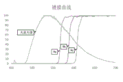
FIG. 1 is a schematic diagram of a relationship between a coated area of a beam-splitting diaphragm and an incident angle thereof;
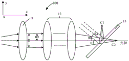
FIG. 2 is a schematic view of the construction of the initial state of the first embodiment of the beam calibration apparatus of the present application;
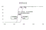
FIG. 3 is a schematic illustration of a coating curve of the beam-splitting assembly shown in FIG. 2;
FIG. 4 is a schematic view of the structure of the adjustment state of the first embodiment of the beam calibration apparatus of the present application;
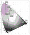
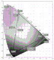
FIGS. 5a and 5b are gamut diagrams of intrinsic color adjustment;
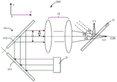
FIG. 6a is a schematic view of the construction of the initial state of a second embodiment of the beam alignment apparatus of the present application;
FIG. 6b is a schematic diagram of the configuration of the adjustment state of the second embodiment of the beam alignment apparatus of the present application;
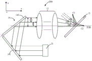
FIG. 7a is a schematic view of the construction of an initial state of a third embodiment of the beam alignment apparatus of the present application;
FIG. 7b is a schematic view of the configuration of the adjustment state of the third embodiment of the beam alignment apparatus of the present application;
FIG. 8 is a schematic view of a fourth embodiment of a beam alignment apparatus of the present application;
FIG. 9 is a schematic diagram of a film coating of the beam splitter assembly shown in FIG. 8 for P light and S light;
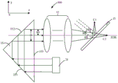
FIG. 10 is a schematic view of the construction of a fifth embodiment of the beam alignment apparatus of the present application;
FIG. 11 is a schematic diagram of an embodiment of a projection device of the present application;
FIG. 12 is a flow chart of an embodiment of a beam calibration method of the present application.
Detailed Description
The following description of the embodiments of the present application will be made clearly and fully with reference to the accompanying drawings, in which it is evident that the embodiments described are only some, but not all, of the embodiments of the present application. All other embodiments, which can be made by one of ordinary skill in the art without undue burden from the present disclosure, are within the scope of the present disclosure.
The terms "first," "second," and the like in this application are used for descriptive purposes only and are not to be construed as indicating or implying relative importance or implicitly indicating the number of technical features indicated. In the description of the present application, the meaning of "plurality" means at least two, for example, two, three, etc., unless specifically defined otherwise. Furthermore, the terms "comprise" and "have," as well as any variations thereof, are intended to cover a non-exclusive inclusion. For example, a process, method, system, article, or apparatus that comprises a list of steps or elements is not limited to only those listed steps or elements but may include other steps or elements not listed or inherent to such process, method, article, or apparatus. And the term "and/or" is merely an association relation describing the association object, and indicates that three relations may exist, for example, a and/or B may indicate: a exists alone, A and B exist together, and B exists alone. In addition, the character "/" herein generally indicates that the front and rear associated objects are an "or" relationship.
The functions of optical devices such as a light-splitting film and a polarization conversion film are generally realized through film plating, and common film plating is generally aimed at angle film plating, namely film plating curves corresponding to light beams with different incident angles are different for the same light-splitting film. As shown in fig. 1, the incident angles of the light beam incident on the beam-splitting diaphragm are respectively θa, θb and θc, the magnitude relation among the three incident angles is θa > θb > θc, and as the incident angle is larger, the corresponding coating curves of the light beam deviate in the short wave direction, and the cut-off wavelengths corresponding to the three incident angles are respectively 580nm, 600nm and 620nm, namely, the coating curves of the beam-splitting diaphragm deviate in the short wave direction along with the increase of the incident angle, and the corresponding cut-off wavelengths deviate in the short wave direction. When the coating curve of the light-splitting membrane is deviated due to the deviation of the coating of the light-splitting membrane, the light-splitting ratio of the light-splitting membrane to the incident light is changed, so that the color of the emergent light beam is deviated.
The application proposes a beam calibration device comprising a color calibration assembly, a beam collimation assembly and a beam splitting assembly. The color calibration assembly is used for guiding the received light beam to the light beam collimation assembly; the beam collimation assembly is used for converging the light beams emitted by the color calibration assembly to the beam splitting assembly; the beam splitting component is used for receiving the light beam emitted by the light beam collimation component and splitting the light beam. The relative position between the color calibration assembly and the beam collimation assembly is adjustable, and the displacement between the optical axis of the light beam emitted by the color calibration assembly and the optical axis of the light beam collimation assembly is adjusted by adjusting the relative position between the color calibration assembly and the beam collimation assembly, so that the color calibration of the light beam emitted by the beam calibration device is realized.
Referring to fig. 2, fig. 2 is a schematic structural diagram of a first embodiment of a beam calibration apparatus according to the present application. As shown in fig. 2, the beam calibration apparatus 100 of the present embodiment may include a color calibration assembly 11, a beam collimation assembly 12, and a beam splitting assembly 13, which are sequentially disposed; the light beam emitted from the light source assembly (not shown in the figure) is incident to the color calibration assembly 11, the color calibration assembly 11 receives the light beam and guides the light beam to the light beam collimation assembly 12, the light beam collimation assembly 12 further converges the light beam emitted from the color calibration assembly 11 to the light splitting assembly 13, the light splitting assembly 13 further splits the light beam, and the first light beam C1 and the second light beam C2 are emitted from two sides of the light splitting assembly 13 respectively, wherein an optical axis of the light beam collimation assembly 12 is shown by a dotted line penetrating through the light beam calibration device. The relative position between the color calibration assembly 11 and the beam collimation assembly 12 is adjustable, so as to adjust the displacement between the optical axis of the beam emitted from the color calibration assembly 11 and the optical axis of the optical axis collimation assembly, and further improve the color of the beam emitted from the beam calibration device 100, i.e. the color of the first light split C1 and the second light split C2.
Further, the beam collimation component 12 is a focusing collimation device in this embodiment, and in one embodiment may be a lens group formed by a plurality of optical lenses, which satisfies the following formula: h=f tan α. Where H is the imaging object height of the beam collimation assembly 12, f is the focal length of the beam collimation assembly 12, and α is the angle of the beam exiting the beam collimation assembly 12 with respect to its optical axis. It can be understood that when the light beam with the width D enters the beam collimation component 12, if the optical axis of the light beam coincides with the optical axis of the beam collimation component 12, the imaging object height of the beam collimation component 12 is D/2; when the optical axis of the light beam deviates from the optical axis of the light beam collimation component 12 in the direction perpendicular to the optical axis of the light beam collimation component 12, the height H of the imaging object of the light beam collimation component 12 is changed, and the focal length f is a fixed value, the value of tan alpha can be changed, the included angle alpha of the light beam emitted by the light beam collimation component 12 relative to the optical axis is correspondingly changed, and if the position of the light splitting component 13 is unchanged, the incident angle theta of the light beam emitted by the light beam collimation component 12 relative to the light splitting component 13 can be changed. The present embodiment adjusts the movement of the light beam emitted from the color collimating component 11 relative to the optical axis of the light beam collimating component 12 in the direction perpendicular to the optical axis of the light beam collimating component 12 by moving the color collimating component 11 and/or the light beam collimating component 12 with adjustable positions, that is, adjusts the displacement between the optical axis of the light beam emitted from the color collimating component 11 and the optical axis of the light beam collimating component 12, and further adjusts the incident angle of the light beam emitted from the light beam collimating component 12 relative to the light splitting component 13. According to the analysis of the film coating curve of the beam splitter, changing the incident angle of the light beam incident on the beam splitter 13 is equivalent to adjusting the offset state of the film coating curve, so as to calibrate the film coating curve, thereby achieving the purpose of improving the color of the light beam emitted from the light beam calibration device 100.
The beam color calibration of this embodiment is further described:
let the beam calibration apparatus 100 shown in fig. 2 beThe color collimating component 11 and the beam collimating component 12 are respectively located at respective initial positions (in this embodiment, the positions of the optical axes of the light beams emitted by the color collimating component 11 and the optical axis of the beam collimating component 12 are taken as initial positions), at this time, the displacement between the optical axes of the light beams and the optical axis of the beam collimating component 12 is zero, the beam splitting component 13 is located behind the beam collimating component 12 and is fixed in position, the light beams are transmitted along the +z direction shown in fig. 2, the y direction is the vertical direction (parallel to the paper surface) perpendicular to the optical axis of the beam collimating component 12, and the x direction is the horizontal direction (perpendicular to the paper surface) perpendicular to the beam collimating component 12. If the width of the light beam is D, the imaging object height of the light beam collimation component 12 is half-height D/2 of the light beam; the beam collimation component 12 converges the light beam to the beam splitting component 13, and the optical axis of the light beam is at an incident angle theta 0 Incident to the beam-splitting component 13, the incidence angles of the edge rays of the light beam relative to the beam-splitting component 13 are respectively theta 1 And theta 2 The light beam is split into a first light beam and a second light beam at the beam splitting assembly 13 based on a coating film curve of the beam splitting assembly 13. Fig. 3 shows a coating curve of the light splitting assembly 13 according to the present embodiment, wherein the curve deviated to the long wave direction is a theoretical coating curve of the light splitting assembly 13 (a coating curve when the coating of the light splitting assembly 13 meets the theoretical light splitting requirement), and the corresponding cut-off wavelength is set to a; in practical applications, the actual coating curve of the beam splitter 13 deviates from the ideal coating curve due to coating errors caused by the influence of the processing technology, the processing environment, etc. (in this embodiment, the actual coating curve deviates from the ideal coating curve in the short-wave direction) of the beam splitter 13, and the corresponding cut-off wavelength is b. As can be seen from this, the shift of the cut-off wavelength causes the beam splitting component 13 to split the first beam and the second beam, so that the color of the split beam is deviated. Let a be 600nm and b be 580nm; the first light beam and the second light beam after theoretical light splitting are light with the wavelength of more than 600nm and light with the wavelength of less than 600nm respectively; when the actual cut-off wavelength is shifted to the shortwave and becomes 580nm, the incident angle is unchanged, and the actual cut-off wavelength is 580nm, and the first light beam and the second light beam after actual light splitting are respectively wavesThe actual spectral ratio of the first light beam and the second light beam is shifted from the theoretical spectral ratio by light having a length less than 580nm and light having a wavelength greater than 580nm, and the color of the first light beam and the second light beam is different from the theoretically required color due to the change of the spectrum.
Referring further to fig. 4, according to the beam calibration apparatus 100 of the present embodiment, the relative position between the color calibration assembly 11 and the beam calibration assembly 12 is adjusted, so that the beam emitted from the color calibration assembly 11 moves in the +y direction in the direction perpendicular to the beam calibration assembly 12, and the optical axis of the beam is displaced by an amount s in the +y direction relative to the optical axis of the beam calibration assembly 12. At this time, for the beam collimation assembly 12, the imaging object height H becomes larger, the value of tan α becomes larger correspondingly, and the included angle α between the light beam emitted from the beam collimation assembly 12 and the optical axis becomes larger; according to the angle relationship, the sum of the included angle of the light beam emitted from the beam collimating component 12 relative to the optical axis thereof and the incident angle of the light beam incident on the beam splitting component 13 is equal to the included angle of the normal line of the beam splitting component 13 relative to the optical axis of the beam collimating component 12, while in this embodiment, the position of the beam splitting component 13 is unchanged, the included angle of the normal line of the beam splitting component relative to the optical axis of the beam collimating component 12 is unchanged, and when the included angle α of the light beam emitted from the beam collimating component 12 relative to the optical axis thereof is increased, the incident angle of the light beam incident on the beam splitting component 13 is reduced. In connection with fig. 4, the incidence angle θ of the main optical axis of the light beam to the beam-splitting element 13 3 Compared with the incident angle theta shown in fig. 2 0 Reducing the incidence angle theta of the marginal ray of the light beam to the beam splitting assembly 13 4 And theta 5 Also compared to the incident angle θ shown in FIG. 2 1 And theta 2 And (3) reducing. As is clear from the relationship between the film plating curve of the spectroscopic film and the incident angle of the light beam shown in fig. 1, when the incident angle is reduced, the film plating curve of the spectroscopic film is shifted in the wavelength direction. Thus, as shown in fig. 3, the actual coating curve is shifted to the theoretical coating curve by decreasing the incident angle of the light beam of the spectroscopic assembly 13; the calibration of the actual coating curve of the beam splitter assembly 13 is achieved, thereby improving the color of the beam emitted by the beam calibration device 100.
In addition, according to the above formula satisfied by the beam collimation assembly 12, the specific adjustment of the angle value of the incident angle can be controlled by generating a displacement s between the optical axis of the beam and the optical axis of the beam collimation assembly 12, and the larger the displacement s, the more the incident angle is reduced.
It will be appreciated that the beam exiting the color collimating assembly 11 in this embodiment may also be moved in other directions perpendicular to the beam collimating assembly 12, such as the-y direction or the x direction. It should be noted that, when the beam emitted from the color calibration assembly 11 moves in the direction perpendicular to the-y direction of the beam collimation assembly 12, the displacement s generated between the optical axis of the beam and the optical axis of the beam collimation assembly 12 is negative, the object height of the beam collimation assembly 12 becomes smaller, the value of tan α becomes smaller, and the value of θ becomes larger, and at this time, the calibration of the film coating curve of the beam splitting assembly 13 is to shift the actual film coating curve of the beam splitting assembly 13 in the short-wave direction. The movement of the beam emitted from the color calibration assembly 11 in other directions perpendicular to the beam collimation assembly 12 is similar to the movement in the y direction, and the specific movement direction thereof can be adjusted according to the actual light path design and requirements, which is not limited in this application.
Further, the beam calibration device 100 of the present embodiment can calibrate the intrinsic colors of the three primary colors in the imaging of the three primary colors based on the color calibration of the split beam, where the intrinsic colors refer to the colors of the emitted color light, and if the beam calibration device 100 is used in a projector, the colors of the beam emitted by the projector. If the light beam incident on the color calibration assembly 11 is tri-primary color light including red light, green light and blue light, the structure of the light beam calibration apparatus 100 is also shown in fig. 2, and fig. 3 shows a film coating curve of the light splitting assembly 13 included therein, wherein the curve deviated in the long wave direction is a theoretical film coating curve of the light splitting assembly 13, and the corresponding cut-off wavelength is set to 600nm; the curve in the short wave direction is the actual coating curve of the beam splitter 13, and the corresponding cut-off wavelength is 580nm.
According to the theoretical film-plating curve of the light-splitting component 13, the first light beam and the second light beam split by the light-splitting component 13 are respectively red light with the wavelength of more than 600nm and mixed light of blue light and green light with the wavelength of less than 600nm, and the theoretical color gamut can be the theoretical color gamut formed by solid triangles shown in fig. 5 a. When the actual coating curve of the light splitting assembly 13 is shifted to the short wave direction, the first light beam and the second light beam split by the light splitting assembly 13 are respectively the red light with the wavelength greater than 580nm and the mixed light of the blue light and the green light with the wavelength less than 580nm, and the wavelength of the blue light is always smaller than the cut-off wavelength, so the influence on the splitting of the blue light is small, the split green light lacks the light ranging from 580nm to 600nm relative to the theoretical green light, the split red light increases the light ranging from 580nm to 600nm relative to the theoretical red light, and the color coordinates of the actual green light and the actual red light are shifted. In an embodiment, the color coordinates of the red light and the green light can be adjusted by adding complementary lasers of corresponding colors in the optical path system, that is, adding the green laser and the red laser respectively to obtain intrinsic green light by mixing the green laser and the green fluorescence, and obtaining intrinsic red light by mixing the red laser and the red fluorescence, so that an actual color gamut (thick dot triangle) formed by the intrinsic red light, the intrinsic green light and the intrinsic blue light can cover a theoretical color wheel, but adding additional complementary lasers can cause cost increase, and color correction software is required to modulate the actual color gamut to obtain the theoretical color gamut, and the modulation process can cause light loss and lower overall brightness; in addition, the addition of the supplementary laser can increase the heat of the optical path system, which is unfavorable for the heat dissipation of the optical path structure, in particular the heat dissipation of the image modulation device (such as a spatial light modulator and the like). In addition, if the offset of the coating curve of the beam splitter 13 relative to the theoretical coating curve is large, even if the complementary laser light of the corresponding color is supplemented, the color coordinates of the intrinsic red light and/or the intrinsic green light cannot be calibrated out of the theoretical color gamut, as shown in fig. 5b, and the color coordinates of the intrinsic red light are still within the range of the theoretical color gamut when the red laser light is supplemented, so that the theoretical color gamut cannot be covered.
In this application, based on the light beam calibration apparatus 100 of this embodiment, the relative position between the color calibration assembly 11 and the light beam collimation assembly 12 can be adjusted, so that the light beam emitted from the color calibration assembly 11 moves toward the +y direction in the direction perpendicular to the light beam collimation assembly 12, the displacement s is generated between the optical axis of the light beam and the optical axis of the light beam collimation assembly 12, the height of the imaged object of the light beam collimation assembly 12 is increased, the value of the incident angle θ when the emitted light beam enters the light splitting assembly 13 is reduced, the actual coating curve is offset towards the theoretical coating curve, the light splitting ratio of the light splitting assembly 13 to red light and green light is adjusted, the light splitting ratio of the red light and green light is made to meet the theoretical light splitting ratio as much as possible, the color coordinates of the intrinsic red light and the intrinsic green light are modulated, and the calibration of the intrinsic colors of the three primary colors in the three primary colors is realized.
As further shown in fig. 2 and 4, in one embodiment, the color collimating component 11 may be a lens group including at least one lens, and the light beam of the light source component enters the color collimating component 11 and then exits as parallel light. At this time, the relative displacement between the optical axis of the light beam emitted by the color collimating component 11 and the optical axis of the light beam collimating component 12 can be changed by moving the color collimating component 11 in the direction perpendicular to the optical axis of the light beam collimating component 12, that is, adjusting the relative position between the color collimating component 11 and the light beam collimating component 12.
In this embodiment, an adjusting bracket for adjusting the position of the color calibration assembly 11 may be provided, and the adjusting bracket may include one of a plurality of adjusting mechanisms such as an adjusting rod, an adjusting motor, an adjusting gear, an adjusting slide rail, or a combination of a plurality of adjusting mechanisms in the x direction and the y direction.
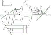
Further, as shown in fig. 6a and 6b, in other embodiments, the color calibration assembly 11 may also be a mirror assembly 14, and in this embodiment, a pair of mirrors consisting of two mirrors is taken as an example, the light beam emitted from the light source assembly is incident on the first mirror 141, reflected by the first mirror 141 to the second mirror 142, and further reflected by the second mirror 142 to the color calibration assembly 11. As shown in fig. 6a, the first reflecting mirror 141, the second reflecting mirror 142 and the beam collimating component 12 are respectively located at respective initial positions, at this time, the optical axis of the beam reflected by the second reflecting mirror 142 coincides with the optical axis of the beam collimating component 12, and at this time, the optical path structure behind the color collimating component 11 is the same as that shown in fig. 2, and details are not repeated here.
In this embodiment, the displacement between the optical axis of the light beam emitted from the second mirror 142 and the optical axis of the light beam collimating component 12 can be adjusted by deflecting the first mirror 141 and the second mirror 142. As shown in fig. 6b, the first mirror 141 and the second mirror 142 deflect in the-y direction at the same time, at this time, the optical paths of the light source assembly incident on the first mirror 141 and the second mirror 142 are shifted, and finally the light beam exiting from the second mirror 142 moves in the +y direction, that is, the displacement between the optical axis of the light beam exiting from the second mirror 142 and the optical axis of the light beam collimating assembly 12 is adjusted in the y direction, thereby improving the color of the light beam exiting from the light beam collimating device 200, and the improvement process for realizing the color of the light beam exiting from the light beam collimating device 200 in this embodiment is the same as the improvement process for the embodiment shown in fig. 2 to 4, and is not repeated here.
Further, the angle between the first mirror 141 and the second mirror 142 in this embodiment is kept constant, that is, the first mirror 141 and the second mirror 142 are rotated synchronously when they are rotated. In one embodiment, the angle between the first mirror 141 and the second mirror 142 is maintained at 90 °, i.e., the first mirror 141 and the second mirror 142 remain perpendicular at all times.
In other embodiments, the mirror assembly 14 may also include more mirrors, and the beam may be incident on the beam collimation assembly 12 in parallel by designing the relative positional relationship between the mirrors, which is not particularly limited in this application.
Further, referring to fig. 7a and 7b, in still another embodiment, the color calibration assembly 11 may be a right angle prism 15, two right angle surfaces of the right angle prism 15 are two reflecting surfaces 151 and 152, and the light beam emitted from the light source assembly enters the right angle prism 15 from the inclined surface 153 of the right angle prism 15, is reflected to the second reflecting surface 152 on the first reflecting surface 151, is further reflected by the second reflecting surface 152, and then exits from the inclined surface 153 thereof. As shown in fig. 7a, the right-angle prism 15 and the beam collimation assembly 12 are respectively located at respective initial positions, at this time, the optical axis of the beam emitted from the right-angle prism 15 coincides with the optical axis of the beam collimation assembly 12, and at this time, the optical path structure behind the color calibration assembly 11 is the same as that shown in fig. 2, and will not be described again here.
In this embodiment, the displacement between the optical axis of the beam emitted by the right angle prism 15 and the optical axis of the beam collimation assembly 12 can be adjusted by deflecting the right angle prism. As shown in fig. 7b, the rectangular prism 15 deflects in the-y direction, at this time, the light path of the incident beam of the light source system between the first reflecting surface and the second reflecting surface of the rectangular prism 15 is deviated, and finally the beam exiting from the rectangular prism 15 moves in the +y direction, that is, the displacement between the optical axis of the beam exiting from the rectangular prism 15 and the optical axis of the beam collimating assembly 12 is adjusted in the y direction, thereby improving the color of the beam exiting from the beam collimating device 300, and the improvement process of the color of the beam exiting from the beam collimating device 300 is implemented in this embodiment as the above-mentioned improvement process of the embodiment shown in fig. 2 to 4, and is not repeated here.
In the beam alignment apparatus shown in fig. 6 and 7, an adjustment bracket for adjusting the rotation angle thereof may be provided to the mirror assembly 14 and the right angle prism 15, and the adjustment bracket may include one of a plurality of adjustment mechanisms such as a rotation gear, an adjustment motor, an adjustment slide rail, or a combination of a plurality of adjustment mechanisms.
In yet another embodiment, the relative position between the color collimating component 11 and the light beam collimating component 12 may be adjusted by moving the position adjustment of the light beam collimating component 12 in the direction perpendicular to the optical axis of the light beam collimating component 12, so as to change the relative displacement between the optical axis of the light beam emitted from the color collimating component 11 and the optical axis of the light beam collimating component 12, thereby improving the color of the light beam emitted from the light beam collimating device 100, and the improvement process of the color of the light beam emitted from the light beam collimating device 100 in this embodiment is the same as the improvement process of the embodiment shown in fig. 2 to 4, and is not repeated here. In addition, if the light source assembly has a simple structure, the relative displacement between the optical axis of the light beam emitted from the color calibration assembly 11 and the optical axis of the light beam collimation assembly 12 can be adjusted by moving the position of the light source. As shown in fig. 6a and 7a, moving the light source assembly in a direction perpendicular to the optical axis of the beam collimation assembly 12, the displacement between the optical axis of the beam exiting the color collimation assembly 11 and the optical axis of the beam collimation assembly 12 can also be adjusted, improving the color of the beam exiting the beam collimation device 200, 300.
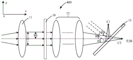
Further, referring to fig. 8, fig. 8 is a schematic structural diagram of a beam calibration apparatus according to another embodiment of the present application. As shown in fig. 8, the beam calibration apparatus 400 of the present embodiment may further include a polarization converter 16 on the basis of the beam calibration apparatus 100 shown in fig. 2, where the polarization converter 16 is disposed between the color calibration assembly 11 and the beam calibration assembly 12, and is configured to receive the light beam emitted from the color calibration assembly 11, modulate the polarization state of the light beam, and convert the light beam into a light beam with a single polarization state. The beam collimation assembly 12 and the beam splitting assembly 13 are identical to the beam collimation assembly 12 and the beam splitting assembly 13 in the embodiment shown in fig. 1 to 7, and are not described here again.
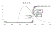
In this embodiment, the function of the polarization converter 16 is implemented by coating, similar to that of the light splitting component 13, there is a certain coating error, so that the polarization converter 16 cannot completely convert the incident light beam into a light beam with a single polarization state, and at this time, because the light splitting component 13 has a certain difference between the P-light coating curve and the S-light coating curve of the P-polarization state, as shown in fig. 9, when the incident light has the P-light and the S-light, the actual coating curve of the light beam by the light splitting component 13 is located between the P-light coating curve and the S-light coating curve. If the S light is needed, the actual film coating curve is shifted to the short wave direction relative to the S light film coating curve; if the light is P light, the actual film coating curve is shifted to the long wave direction relative to the P light film coating curve. At this time, by changing the relative position between the color calibration assembly 11 and the beam collimation assembly 12, the displacement between the optical axis of the beam emitted from the color calibration assembly 11 and the optical axis of the beam collimation assembly 12 can be adjusted, so that the actual coating curve is calibrated to the theoretical coating curve, and the color of the beam emitted from the beam calibration apparatus 400 is improved.
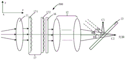
Further, referring to fig. 10, fig. 10 is a schematic structural diagram of a beam calibration apparatus according to another embodiment of the present application. As shown in fig. 10, the beam calibration apparatus 500 of the present embodiment may further include a light homogenizing component 17 on the basis of the beam calibration apparatus 400 shown in fig. 8, where the light homogenizing component 17 is disposed between the color calibration component 11 and the beam collimation component 12, and is configured to receive the light beam emitted from the color calibration component 11 and perform a homogenization treatment on the light beam, so that the light beam incident on the beam collimation component 12 is a uniformly distributed light beam. In this embodiment, the light homogenizing component 17 may be a fly-eye lens pair, including a first fly-eye lens 171 and a second fly-eye lens 172, where the first fly-eye lens 171 is located on the effective focal length of the second fly-eye lens 172, and the beam plane distribution on the first fly-eye lens 171 will be imaged at infinity.
In other embodiments, the light homogenizing unit 17 may be another light homogenizing device such as a light homogenizing rod, which is not particularly limited in this application.
It will be appreciated that the polarization converter 16 shown in fig. 9 and/or the light homogenizing assembly 17 shown in fig. 10 may also be provided in the beam alignment apparatus 100 shown in fig. 6 to 7.
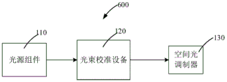
As further shown in fig. 11, the present application also proposes a projection device 600 comprising a light source assembly 110, a beam alignment device 120 and a spatial light modulator 130; the light source assembly 110 provides illumination light; the beam calibration device 120 is configured to receive the illumination light, calibrate the illumination light, and guide the illumination light to the spatial light modulator 130; the spatial light modulator 130 modulates the illumination light to form image light to be projected onto a projection plane.
In this embodiment, the beam calibration apparatus 120 may be any of the beam calibration apparatuses shown in fig. 2 to 10.
The light source assembly 110 may be a hybrid light source composed of a fluorescent light source for providing a broad spectrum of fluorescence to be separated into two primary color fluorescence including primary color spectrums having different wavelength ranges at a light splitting assembly of the beam calibration device, and a laser light source for providing a third primary color light. The three primary color lights are respectively guided to the spatial light modulator 130 to perform image light modulation to form image light.
In an embodiment, as shown in fig. 2 to 10, the beam splitting component splits the light beam into a first light beam C1 and a second light beam C2, and the corresponding spatial light modulator 130 may be configured as a dual spatial light modulator, where the two spatial light modulators modulate the first light beam C1 and the second light beam C2, respectively. In another embodiment, the mixed light of blue light and green light may be further split, and the corresponding spatial light modulator 130 may be configured as three spatial light modulators that modulate three primary color lights, respectively.
The projection device 600 of the present embodiment can calibrate the intrinsic color of the beam of light incident on the spatial light modulator 130 after splitting by using the beam calibration device 120, so as to calibrate the actual color gamut of the beam of light; in addition, light loss caused by software modulation can be avoided, and image brightness is improved. Meanwhile, the dependence of the projection equipment on the supplementary laser can be weakened, the heat dissipation of the projection equipment is facilitated, and the cost is reduced.
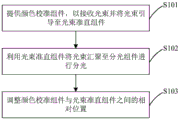
Further, as shown in fig. 12, the present application further proposes a beam calibration method, which includes:
in step S1, a color collimating assembly is provided to receive the light beam and direct the light beam to the beam collimating assembly;
in step S2, the beam is converged to the beam splitting component by using the beam collimation component for splitting;
in step S3, the relative position between the color calibration assembly and the beam collimation assembly is adjusted so as to generate a displacement of the beam emitted by the color calibration assembly in a direction perpendicular to the optical axis of the beam collimation assembly, thereby improving the color of the beam emitted by the beam splitting assembly.
The beam calibration method of the present embodiment can be applied to the beam calibration apparatus shown in fig. 2 to 10, or to the projection apparatus shown in fig. 11.
The foregoing description is only of embodiments of the present application, and is not intended to limit the scope of the patent application, and all equivalent structures or equivalent processes using the descriptions and the contents of the present application or other related technical fields are included in the scope of the patent application.
Claims (11)
1. The light beam calibration device is characterized by comprising a color calibration assembly, a light beam collimation assembly and a light splitting assembly which are sequentially arranged:
a color collimating assembly for receiving a light beam and directing the light beam to the light beam collimating assembly;
the light beam collimation assembly is used for converging the light beams emitted by the color calibration assembly to the light splitting assembly;
the beam splitting component is used for receiving the light beam and splitting the light beam;
the relative position between the color calibration assembly and the beam collimation assembly is adjustable, and the displacement between the optical axis of the beam emitted by the color calibration assembly and the optical axis of the beam collimation assembly is adjusted, so that the color of the beam emitted by the beam calibration device is improved.
2. The beam alignment apparatus of claim 1, wherein the color alignment assembly is a lens assembly;
the lens component is adjustable in position relative to the light beam collimation component in the direction perpendicular to the optical axis of the light beam collimation component so as to adjust the displacement between the optical axis of the light beam emitted by the lens component and the optical axis of the light beam collimation component, and further improve the color of the light beam emitted by the light beam collimation device.
3. The beam alignment apparatus of claim 1, wherein the color alignment assembly is a mirror assembly;
the reflecting mirror component can deflect and adjust relative to the light beam collimation component so as to adjust the displacement between the optical axis of the light beam emitted by the reflecting mirror component and the optical axis of the light beam collimation component, and further improve the color of the light beam emitted by the light beam collimation device.
4. The beam alignment apparatus of claim 1, wherein the color alignment assembly is a right angle prism;
the right-angle prism can deflect and adjust relative to the light beam collimation component so as to adjust the displacement between the optical axis of the light beam emitted by the right-angle prism and the optical axis of the light beam collimation component, and further improve the color of the light beam emitted by the light beam collimation device.
5. The beam alignment apparatus of claim 1, wherein the beam exiting the color alignment assembly is a parallel beam.
6. The beam alignment apparatus of claim 1, further comprising a polarization conversion device;
the polarization conversion device is positioned between the color calibration component and the light beam collimation component and is used for carrying out polarization conversion on the light beam.
7. The beam alignment apparatus of claim 1, further comprising a light homogenizing assembly;
the light homogenizing component is positioned between the color calibration component and the light beam collimation component and is used for homogenizing the light beam.
8. The beam alignment apparatus of claim 7 wherein the light homogenizing element is a fly eye lens pair.
9. A projection device comprising a light source assembly, a beam alignment device and a spatial light modulator;
the light source assembly provides illumination light;
the beam calibration device is used for receiving the illumination light, calibrating the illumination light and guiding the illumination light to the spatial light modulator;
the spatial light modulator modulates the illumination light to form image light and projects the image light to a projection plane;
wherein the beam alignment apparatus is a beam alignment apparatus as claimed in any of claims 1-8.
10. A method of beam alignment comprising:
providing a color collimating assembly to receive a light beam and direct the light beam to a beam collimating assembly;
converging the light beam to a light splitting component by utilizing the light beam collimation component for light splitting;
and adjusting the relative position between the color calibration assembly and the beam collimation assembly so as to enable the light beam emitted by the color calibration assembly to generate displacement in the direction perpendicular to the optical axis of the beam collimation assembly, thereby improving the color of the light beam emitted by the beam splitting assembly.
11. The beam alignment method according to claim 10, wherein the beam alignment method is applied to the beam alignment apparatus according to any one of claims 1 to 8.
Priority Applications (2)
| Application Number | Priority Date | Filing Date | Title |
|---|---|---|---|
| CN201911325091.5A CN113009754B (en) | 2019-12-20 | 2019-12-20 | Beam calibration device, projection device and beam calibration method |
| PCT/CN2020/137082 WO2021121301A1 (en) | 2019-12-20 | 2020-12-17 | Light beam calibration device, projection device, and light beam calibration method |
Applications Claiming Priority (1)
| Application Number | Priority Date | Filing Date | Title |
|---|---|---|---|
| CN201911325091.5A CN113009754B (en) | 2019-12-20 | 2019-12-20 | Beam calibration device, projection device and beam calibration method |
Publications (2)
| Publication Number | Publication Date |
|---|---|
| CN113009754A CN113009754A (en) | 2021-06-22 |
| CN113009754B true CN113009754B (en) | 2023-04-28 |
Family
ID=76382016
Family Applications (1)
| Application Number | Title | Priority Date | Filing Date |
|---|---|---|---|
| CN201911325091.5A Active CN113009754B (en) | 2019-12-20 | 2019-12-20 | Beam calibration device, projection device and beam calibration method |
Country Status (2)
| Country | Link |
|---|---|
| CN (1) | CN113009754B (en) |
| WO (1) | WO2021121301A1 (en) |
Citations (5)
| Publication number | Priority date | Publication date | Assignee | Title |
|---|---|---|---|---|
| JP2001209140A (en) * | 2000-01-26 | 2001-08-03 | Seiko Epson Corp | Projector and optical device used in it |
| JP2008058558A (en) * | 2006-08-31 | 2008-03-13 | Hitachi Ltd | Projection type video display device |
| CN101598889A (en) * | 2005-07-19 | 2009-12-09 | 株式会社日立制作所 | Projection type video display device and color separating unit |
| CN102033400A (en) * | 2005-09-01 | 2011-04-27 | 精工爱普生株式会社 | Projector |
| CN102914938A (en) * | 2011-08-02 | 2013-02-06 | 精工爱普生株式会社 | Projector |
Family Cites Families (4)
| Publication number | Priority date | Publication date | Assignee | Title |
|---|---|---|---|---|
| JP2008209888A (en) * | 2007-01-31 | 2008-09-11 | Sony Corp | Optical device and projection type display device |
| JP2009186704A (en) * | 2008-02-06 | 2009-08-20 | Seiko Epson Corp | Image display device and projector |
| JP6270407B2 (en) * | 2013-10-23 | 2018-01-31 | キヤノン株式会社 | Light source device and projection display device |
| CN203982065U (en) * | 2014-08-15 | 2014-12-03 | 广景科技有限公司 | DLP minitype projection machine |
-
2019
- 2019-12-20 CN CN201911325091.5A patent/CN113009754B/en active Active
-
2020
- 2020-12-17 WO PCT/CN2020/137082 patent/WO2021121301A1/en active Application Filing
Patent Citations (5)
| Publication number | Priority date | Publication date | Assignee | Title |
|---|---|---|---|---|
| JP2001209140A (en) * | 2000-01-26 | 2001-08-03 | Seiko Epson Corp | Projector and optical device used in it |
| CN101598889A (en) * | 2005-07-19 | 2009-12-09 | 株式会社日立制作所 | Projection type video display device and color separating unit |
| CN102033400A (en) * | 2005-09-01 | 2011-04-27 | 精工爱普生株式会社 | Projector |
| JP2008058558A (en) * | 2006-08-31 | 2008-03-13 | Hitachi Ltd | Projection type video display device |
| CN102914938A (en) * | 2011-08-02 | 2013-02-06 | 精工爱普生株式会社 | Projector |
Also Published As
| Publication number | Publication date |
|---|---|
| CN113009754A (en) | 2021-06-22 |
| WO2021121301A1 (en) | 2021-06-24 |
Similar Documents
| Publication | Publication Date | Title |
|---|---|---|
| EP3598229B1 (en) | Light source apparatus and projection system | |
| US11243460B2 (en) | Light source device and projection system | |
| US9519204B2 (en) | Light source apparatus used in a projection type image display apparatus | |
| US10203592B2 (en) | Image projection apparatus | |
| US9638988B2 (en) | Light multiplexer with color combining element | |
| CN113376947A (en) | Multicolor light source and projection equipment | |
| US8267522B2 (en) | Optical element, illumination apparatus, and projection display apparatus | |
| CN113009754B (en) | Beam calibration device, projection device and beam calibration method | |
| CN112731749B (en) | Laser projection device | |
| US20070258050A1 (en) | Laser projector | |
| CN217521472U (en) | Laser projection device | |
| US20220357561A1 (en) | Fly-eye lens group, light source device, and projection apparatus | |
| US11204544B2 (en) | Projector | |
| US11503257B2 (en) | Light source device and projection image display device | |
| CN215219403U (en) | Projection device, projection lens assembly and projection system | |
| CN114815481A (en) | Laser projection device | |
| WO2022142218A1 (en) | Laser light source device and projection apparatus | |
| CN112738484B (en) | Laser projection device | |
| US20240248385A1 (en) | Light source device and projection display apparatus | |
| CN117826514A (en) | Optical machine and projector | |
| US10809602B2 (en) | Imager and optical system with imager | |
| CN113138523A (en) | Light source device and projection equipment | |
| CN118409471A (en) | Compact DLP projection optical engine | |
| CN113391507A (en) | Light source module and projection device | |
| CN114690524A (en) | Optical illumination system and laser projection equipment |
Legal Events
| Date | Code | Title | Description |
|---|---|---|---|
| PB01 | Publication | ||
| PB01 | Publication | ||
| SE01 | Entry into force of request for substantive examination | ||
| SE01 | Entry into force of request for substantive examination | ||
| GR01 | Patent grant | ||
| GR01 | Patent grant |
