CN100412635C - Reflective lighting optical system - Google Patents
Reflective lighting optical system Download PDFInfo
- Publication number
- CN100412635C CN100412635C CNB2004100379940A CN200410037994A CN100412635C CN 100412635 C CN100412635 C CN 100412635C CN B2004100379940 A CNB2004100379940 A CN B2004100379940A CN 200410037994 A CN200410037994 A CN 200410037994A CN 100412635 C CN100412635 C CN 100412635C
- Authority
- CN
- China
- Prior art keywords
- optical system
- green
- light
- wire grid
- grid type
- Prior art date
- Legal status (The legal status is an assumption and is not a legal conclusion. Google has not performed a legal analysis and makes no representation as to the accuracy of the status listed.)
- Expired - Fee Related
Links
Images
Classifications
-
- H—ELECTRICITY
- H04—ELECTRIC COMMUNICATION TECHNIQUE
- H04N—PICTORIAL COMMUNICATION, e.g. TELEVISION
- H04N5/00—Details of television systems
- H04N5/74—Projection arrangements for image reproduction, e.g. using eidophor
-
- G—PHYSICS
- G03—PHOTOGRAPHY; CINEMATOGRAPHY; ANALOGOUS TECHNIQUES USING WAVES OTHER THAN OPTICAL WAVES; ELECTROGRAPHY; HOLOGRAPHY
- G03B—APPARATUS OR ARRANGEMENTS FOR TAKING PHOTOGRAPHS OR FOR PROJECTING OR VIEWING THEM; APPARATUS OR ARRANGEMENTS EMPLOYING ANALOGOUS TECHNIQUES USING WAVES OTHER THAN OPTICAL WAVES; ACCESSORIES THEREFOR
- G03B21/00—Projectors or projection-type viewers; Accessories therefor
- G03B21/14—Details
-
- G—PHYSICS
- G03—PHOTOGRAPHY; CINEMATOGRAPHY; ANALOGOUS TECHNIQUES USING WAVES OTHER THAN OPTICAL WAVES; ELECTROGRAPHY; HOLOGRAPHY
- G03B—APPARATUS OR ARRANGEMENTS FOR TAKING PHOTOGRAPHS OR FOR PROJECTING OR VIEWING THEM; APPARATUS OR ARRANGEMENTS EMPLOYING ANALOGOUS TECHNIQUES USING WAVES OTHER THAN OPTICAL WAVES; ACCESSORIES THEREFOR
- G03B21/00—Projectors or projection-type viewers; Accessories therefor
- G03B21/005—Projectors using an electronic spatial light modulator but not peculiar thereto
-
- G—PHYSICS
- G03—PHOTOGRAPHY; CINEMATOGRAPHY; ANALOGOUS TECHNIQUES USING WAVES OTHER THAN OPTICAL WAVES; ELECTROGRAPHY; HOLOGRAPHY
- G03B—APPARATUS OR ARRANGEMENTS FOR TAKING PHOTOGRAPHS OR FOR PROJECTING OR VIEWING THEM; APPARATUS OR ARRANGEMENTS EMPLOYING ANALOGOUS TECHNIQUES USING WAVES OTHER THAN OPTICAL WAVES; ACCESSORIES THEREFOR
- G03B33/00—Colour photography, other than mere exposure or projection of a colour film
- G03B33/10—Simultaneous recording or projection
- G03B33/12—Simultaneous recording or projection using beam-splitting or beam-combining systems, e.g. dichroic mirrors
Landscapes
- Physics & Mathematics (AREA)
- General Physics & Mathematics (AREA)
- Engineering & Computer Science (AREA)
- Multimedia (AREA)
- Signal Processing (AREA)
- Projection Apparatus (AREA)
- Liquid Crystal (AREA)
Abstract
Disclosed is a reflective lighting optical system. The reflective lighting optical system can minimize a back focusing distance and a depth of the system, and improve a lighting efficiency by disposing a wire grid type PBS (Polarized Beam Splitter) at an oblique angle with respect to a short side of an imager.
Description
Technical field
The present invention relates to reflective lighting optical system, more particularly, relate to by becoming the pitch angle that wire grid type PBS (polarization beam splitter) is set with the short side of imager but the back focal length and the height of minimization system, and improve the reflective lighting optical system of illumination efficiency.
Background technology
Recently, display device is designed to tiny and light and has the large scale screen become a kind of general trend.Particularly, manufacturing and designing the display device with large scale screen is vital task of industry.At present, well-known projection TV set is the display device that typically has the large scale screen.
Projection TV is divided into cathode ray tube (CRT) projection TV and liquid crystal display (LCD) projection TV.Liquid crystal display (LCD) projection TV also can be divided into system that adopts transmission LCD and the system that adopts reflective LCD (liquid crystal on silicon (LCoS)).
The system of employing reflective LCD compares with the system that adopts transmission LCD has the lower advantage of panel cost of manufacture.
Below in conjunction with accompanying drawing traditional optical projection system and illuminator are described.
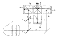
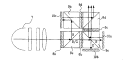
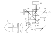
Fig. 1 to Fig. 4 shows the illuminator of various traditional three template reflective LCDs.
At first with reference to Fig. 1, as one of illuminator of the projection TV that adopts reflective LCD, the reflective illumination system of design 3-PBS system makes the light of launching from lamp 1 shine directly into first dichronic mirror 2 by the optically focused camera lens.The redness and the green light that shine directly into first dichronic mirror 2 then see through from this first dichronic mirror 2 from first dichronic mirror, 2 reflection blue rays.
The redness and the green light of reflection shine directly into second dichronic mirror 3.Green light then sees through this second dichronic mirror 3 from second dichronic mirror, 3 reflection red lights.Red, green and blue ray are incident on respectively on first, second and the 3rd PBS4a, 4b and the 4c, and these PBS are arranged on before R, G, the B LCoS plate.
Red, green and blue incident ray is respectively from first, second and the 3rd PBS4a, 4b and 4c reflection, and shines first, second and the 3rd LCoS plate 5a, 5b and 5c respectively.Redness, green and the blue ray generation phase deviation that shines first, second and the 3rd LCoS plate 5a, 5b and 5c respectively is to see through first, second and the 3rd PBS4a, 4b and 4c respectively.
Red, green and blue ray are synthetic and incide projection lens by prism.
As mentioned above, the light path of the reflective illumination system of 3-PBS system comprises three sections; Determined by the lamp 1 and first dichronic mirror 2 for first section, determined by second dichronic mirror, 3, the two LCoS plate 5b and the 2nd PBS 4b for second section, and the 3rd section by a LCoS plate 5a and the 3rd LCoS plate 5c, an X prism 6 and a PBS 4a and the 3rd PBS 4c determine.Like this three sections increase the degree of depth of system.
In addition, system needs a fairly large number of parts as two dichronic mirrors, a reflective mirror, a relay lens that is used to proofread and correct path difference between redness, green and the blue ray, three PBS and an X prism.
Fig. 2 shows three template reflective LCD illuminators of the colored tetrad system of another traditional employing color selector switch rather than relay system.
Illuminator as shown in Figure 2 is designed to utilize the color selector switch to eliminate OPD between redness, green and the blue ray.Just, as the light transmission first color selector switch 8a that launches from lamp 7, blue ray is become subwave (S ripple) and red and green light is exported as main ripple (P ripple).
The blue ray that becomes subwave is shining directly into the 2nd PBS 9b that is positioned at blue LCoS plate front after the reflection on the one PBS 9a, and the redness of P ripple and green light see through a PBS 9a.
Blue ray then in the 2nd PBS 9b reflection, incides the 3rd LCoS plate 10c afterwards, and reflects so that the phase place of blue ray is offset on the 3rd LCoS plate 10c.The blue ray that skew takes place phase place sees through the 2nd PBS 9b, incides the 4th PBS 9d by the 4th color selector switch 8d afterwards.
Become subwave and incide the 3rd PBS 9c during as the green light of main ripple by the second color selector switch 8b.At this moment, do not change as the red light of main ripple and incide the 3rd PBS9c.Therefore, reflection takes place and red light sees through the 3rd PBS 9c at the 3rd PBS 9c in green light, and afterwards, red and green light incides a LCoS plate 10a and the 2nd LCoS plate 10b respectively.
Inciding the redness of a LCoS plate 10a, the 2nd LCoS plate 10b and green light respectively reflects thereon and produces phase shift.Produce dephased redness and green light and incide the 3rd PBS 9c and synthetic again, and make to have identical polarization state, these light waves incide the 4th PBS 9d afterwards.
Redness, green and the blue ray that shines the 4th PBS 9d by the P/S of PBS separate/composite character synthesizes.Light after synthetic incides projection lens.
As mentioned above, because the light path of 3 template reflective LCD illuminators of colored tetrad system is to be provided with the two-stage structure that does not adopt relay system, so its structure can be simplified.Yet, owing to need four color selector switchs and four PBS, thus manufacturing cost increased.
In addition, separate at the P/S that is undertaken by PBS/synthesize in the processing procedure, when incident light is output, may exist to cause incident light wave to have the photoelasticity problem of different polarization lights.
In order addressing the above problem, and to adopt illumination light to improve illumination efficiency, to have proposed to adopt the illuminator of wire grid type PBS as shown in Figure 5 with optical angle.
Figure 3 shows that the traditional illuminator that adopts wire grid type PBS.
As shown in the figure, the illuminator of design makes the light that irradiates from lamp 11 shine directly into the first dichronic mirror 12a by collector lens.The redness and the green light that shine the light of the first dichronic mirror 12a then reflect on this dichronic mirror 12a through the first dichronic mirror 12a blue ray.
The redness and the green light that see through the first dichronic mirror 12a become main ripple and subwave respectively when seeing through color selector switch 14, shine the second wire grid type PBS 13b then.The red light that becomes main ripple sees through the second wire grid type PBS 13b and green light is reflected from it, and afterwards, red and green light incides a LCoS plate 15a and the 2nd LCoS plate 15b respectively.By reflecting from a LCoS plate 15a and the 2nd LCoS plate 15b respectively, red and green light produces phase shift then.Produce dephased redness and green light and incide projection lens by the second wire grid type PBS 13b and the second dichronic mirror 12b.
In addition, the blue ray that reflects from the first dichronic mirror 12a shines the first wire grid type PBS13a, reflects from it then to shine the 3rd LCoS plate 15c.By being reflected by the 3rd LCoS plate 15c, the blue ray that shines the 3rd LCoS plate 15c produces phase shift, then reflects on the second dichronic mirror 12b by the first wire grid type PBS 13a, reenters and is mapped to projection lens.
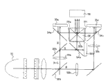
Figure 4 shows that traditional illuminator that another adopts wire grid type PBS.
As shown in the figure, the illuminator of design makes the light that irradiates from lamp 16 shine directly into first dichronic mirror 17 by collector lens.The redness and the green light that shine directly into the light of first dichronic mirror 17 reflect blue ray thereon then by this first dichronic mirror 17.
Blue ray incides the 3rd LCoS plate 21c by the second relay lens 18b, catoptron, the 3rd relay lens 18c and the 3rd wire grid type PBS 20c.
Blue ray is inciding X prism 22 from the 3rd LCoS plate 21c reflection and after producing phase shift by the 3rd wire grid type PBS 20c.
The redness and the green light of reflection shine second dichronic mirror 19 by relay lens 18a.Green light is from the reflection of second dichronic mirror 19 and red light sees through from second dichronic mirror 19.
The green light of reflection reflects on the second wire grid type PBS 20b, incides the 2nd LCoS plate 21b afterwards.Green light produces phase shift to shine the X prism by the second wire grid type PBS 20b through the 2nd LCoS plate 21b.
The red light that sees through from second dichronic mirror 19 reflects at the first wire grid type PBS 20a, incides a LCoS plate 21a afterwards.Green light produces phase shift to shine directly into the X prism by the first wire grid type PBS 20a through a LCoS plate 21a.
Redness, green and blue ray shines directly into projection lens after the X prism is synthetic.
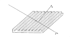
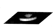
As shown in Figure 5, wire grid type PBS comprises the glass plate that forms predetermined pattern.
The predetermined pattern that forms on the glass plate has tens nm sizes.
When illuminator adopts this wire grid type PBS to make, can solve as stress optic problem various problems such as cost problem and illumination efficiency problem.Yet, the astigmatism problem can appear.
Just, when glass plate is inserted in the imaging len system with the pitch angle, generation will hinder light amphiblestroid certain put the astigmatism of clear focusing, cause the visual field smudgy.
Particularly, when light passed through wire grid type PBS after the reflection of LCoS plate, the astigmatism problem became more serious.
With reference to Fig. 3, the green light that reflects from the 2nd LCoS plate 15b passes through the second wire grid type PBS13b, and passes through the first wire grid type PBS13a from the blue ray of the 3rd LCoS plate reflection.
With reference to Fig. 4, see through the first wire grid type PBS 20a, the second wire grid type PBS 20b and the 3rd wire grid type PBS 20c from the light of a LCoS plate 21a, the 2nd LCoS plate 21b and the 3rd LCoS plate 21c reflection.
As mentioned above, through wire grid type PBS, astigmatism is produced after light reflects from the LCoS plate.
When the astigmatism that produces when LCoS plate light reflected sees through wire grid type PBS is described hereinafter with reference to Fig. 6 to Fig. 8.
Shown in Fig. 6 is the arrangement plan of the projecting lens when light sees through wire grid type PBS.And Fig. 7 and the waveform that Figure 8 shows that the situation of Fig. 6.
When seeing through the situation that is inserted in the wire grid type PBS between projection lens and the LCoS plate with the pitch angle, will be described hereinafter light.
The aberration that produces when light sees through the wire grid type PBS that is inserted in the pitch angle between projection lens and the LCoS plate as shown in Figure 6 is shown in Fig. 7 and Fig. 8.
That is to say, as shown in the figure, the astigmatism problem when light sees through the wire grid type PBS that is inserted in the pitch angle between projection lens and the LCoS plate, occurs.
As mentioned above, traditional reflective illumination system has variety of issue.
That is to say that the reflective illumination system of the 3-PBS system shown in Fig. 1 has owing to a plurality of problems such as three sections light paths so system's degree of depth increase and a plurality of parts of needs.
Although the reflective illumination system of colored tetrad system as shown in Figure 2 owing to adopt four color selector switchs and four PBS, therefore has the cost problem of higher owing to be that two sections light paths have advantage of simple structure.
In addition, separate at the P/S that is undertaken by PBS/synthesize in the processing procedure, when incident light wave is output, may exist to cause incident light wave to have the stress optic problem of different polarization lights.
Although the reflective illumination system that respectively adopts wire grid type has as shown in Figure 3 and Figure 4 solved as the photoelasticity problem, problems such as cost and illumination efficiency, there is the astigmatism problem in this system.
In order to reduce astigmatism, proposed to reduce each wire grid type PBS thickness method or the method for two wire grid type PBS of different directions is set.
Yet when the thickness of wire grid type PBS reduced, glass plate may be out of shape.In addition,, can not offset astigmatism, but its formed motion morphology is circular, makes spot become big even PBS is arranged on different directions.Moreover because PBS has different angles mutually, illuminator can not be designed to a plane.
Summary of the invention
In view of this, the present invention proposes to be used for the optical system of reflective lighting optical system, and this system eliminates fully because one or more problems that the shortcoming of prior art and restriction cause.
The purpose of this invention is to provide a kind of reflective lighting optical system,, can overcome astigmatism and improve illumination efficiency by allowing not incide projection lens by wire grid type PBS from the red, green and blue chrominance signal of LCoS plate reflection.
Another object of the present invention provides a kind of film-type optical module that adopts as wire grid type PBS, minimizes the reflective illumination system of the degree of depth of whole optical system by the back focal length that minimizes projection lens.
A further object of the present invention provides a kind of optical system that adopts the wire grid type PBS of illuminator, does not influence optical property and minimizes the height of this system.
Other advantages of the present invention, purpose and characteristic partly will be described below, and the part those of ordinary skill in the art who has is conspicuous according to the inspection for following content or can acquires from the practice of the present invention.Purpose of the present invention and other advantages can or obtain according to the realization of the concrete structure shown in the description in instructions and claim and the accompanying drawing.
In order to realize purpose of the present invention and other advantages, according to purpose of the present invention, give concrete and extensively description at this, the reflective lighting optical system that is provided comprises: the illuminace component that is arranged on the optical system downside, this illuminace component comprises and is used for alight and makes redness, green and blue ray be divided into three dichronic mirrors in different paths separately that described redness, green and blue ray are aimed at from described light irradiation and with polarization member; And the compound component that is arranged on the optical system upside, this compound component comprises three imagers that are used for phase shift and reflection Red, green and blue ray, become the wire grid type PBS at pitch angle with the shorter side of each described imager, this wire grid type PBS is used to transmit by dichronic mirror and is divided into three redness, green and the blue rays in different paths separately, with the redness, green and the blue ray that are used to reflect by each described imager phase shift and reflection, and the X prism, be used for synthetic redness, green and blue ray and incide projection lens with the light that allows to synthesize.Another aspect of the present invention also provides a kind of reflective lighting optical system, comprises being used for alight; That permission is penetrated from lamp and be divided into three dichronic mirrors in different paths separately with redness, green and blue ray that polarization member is aimed at; Three imagers that are used for phase shift and reflection Red, green and blue ray; Become the wire grid type PBS at pitch angle with the shorter side of each described imager, be used to transmit by dichronic mirror be divided into three separately different paths redness, green and blue ray and be used to reflect redness, green and blue ray by each described imager phase shift and reflection; And the X prism, be used to synthesize redness, green and the blue ray that on wire grid type PBS, reflects so that synthetic light incides projection lens.
Be appreciated that generality description and following detailed for front of the present invention are exemplary and indicative, determined the present invention gives further instruction to claim.
Description of drawings
Accompanying drawing is used to provide further understanding of the present invention, and it is in this manual combined and constitute the part of instructions, and it shows embodiments of the invention and is used for explaining principle of the present invention with text description.In the accompanying drawing:
Fig. 1 to Fig. 4 is the synoptic diagram of the illuminator of various traditional three template reflective LCDs;
Fig. 5 is the stereographic map of wire grid type PBS;
The arrangement plan of projection lens when Fig. 6 sees through wire grid type PBS for light;
Fig. 7 and the oscillogram that Figure 8 shows that the situation of Fig. 6;
Fig. 9 is the synoptic diagram according to the reflective lighting optical system of the first embodiment of the present invention;
Figure 10 does not see through the arrangement plan of the situation that wire grid type PBS advances for the light from LCoS plate reflection;
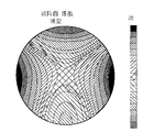
Figure 11 and the oscillogram that Figure 12 shows that the situation of Figure 10;
Figure 13 is the synoptic diagram of reflective lighting optical system according to a second embodiment of the present invention;
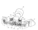
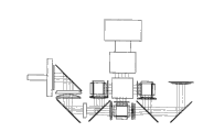
Figure 14 is the perspective illustration of the reflective lighting optical system of a third embodiment in accordance with the invention;
Figure 15 is the synoptic diagram of the following light path part of the reflective lighting optical system shown in Figure 14;
Figure 16 is the synoptic diagram of the last light path part of the reflective lighting optical system shown in Figure 14;
Figure 17 is the front view of the projection lens of the reflective lighting optical system shown in Figure 14;
Figure 18 and 19 is the synoptic diagram in the light path part of vertical and horizontal both direction of the reflective lighting optical system shown in Figure 14.
Embodiment
Now, will describe the preferred embodiments of the present invention in detail, the example shows in the accompanying drawings.Figure 9 shows that the synoptic diagram of reflective lighting optical system according to a preferred embodiment of the invention.
What the present invention relates to is a kind of illuminator of projection display apparatus of the LCoS plate that adopts reflective LCD, and the three template reflective illumination systems that adopt wire grid type PBS are provided, and this system has good performance and lower manufacturing cost.
In the present invention, adopt film-type wire grid type PBS.At this moment, produce, from the reflection of LCoS plate and incide redness, green and the blue ray of projection lens, not by wire grid type PBS but be reflected, incide the X prism then in order to prevent astigmatism.
In other words, because the contrast that traditional PBS photoelasticity causes reduces and the problem of illumination reduction, adopt the wire grid type PBS that the polarization film of identical function is provided with traditional PBS in order to solve.
Wire grid type PBS can realize that P/S separates/synthesizes under less than traditional PBS realization P/S separation/synthetic desired F/#, thereby brighter illuminator is provided.In addition, in order to improve from the contrast of film wire grid type PBS light reflection and that incide projection lens, optical system employing polarization film of the present invention is plugged on the structure between X prism and the wire grid type PBS.
At this, F/# represents the angle of illumination light.Reducing F/# will cause the angle of illumination light to increase.Therefore, the angle increase when illumination light will receive more light.
As shown in the figure, reflective lighting optical system comprises: the lamp 31 of launching red R, green G and blue B light; The first dichronic mirror 32a is used for that send from lamp 31 and be divided into two light paths with light that polarization member aligns by the direction of polarization conversion system (PCS), a) blue ray and the b that send from lamp 31 of transmission) reflection Red and green light; The second dichronic mirror 32b is used for from the red light that sees through relaying camera lens 33a of sodium yellow (G+R) Transflective of first dichronic mirror 32a reflection, and is used to reflect the green light that sees through relaying camera lens 33a through reflection; The second wire grid type PBS 34b is used to transmit green light to the two LCoS plate 35b from second dichronic mirror 32b reflection; The first wire grid type PBS 34a is used to transmit red light to a LCoS plate 35a who sees through from the second dichronic mirror 32b; The 3rd wire grid type PBS 34c is used for transmitting blue light to the three LCoS plate 35c that see through from the first dichronic mirror 32a by the second relay lens 33b, mirror and the 3rd relay lens 33c; X prism 36 is used for syntheticly respectively from redness, green and the blue ray of a LCoS plate 35a, the 2nd LCoS plate 35b and the 3rd LCoS plate 35c reflection, and synthetic light is sent to projection lens 38; And first, second and the 3rd polaroid 37a, 37b and 37c, be used for polarization redness, green and blue ray before light incides X prism 36.
In the constructed in the above reflective illumination system, at first the sodium yellow (G+R) from first dichronic mirror 32a reflection incides the second dichronic mirror 32b.Incide the 2nd LCoS plate 35b from the green light of second dichronic mirror 32b reflection by the second wire grid type PBS 34b.Red light sees through the second dichronic mirror 32b to incide a LCoS plate 35a by the first wire grid type PBS 34a.
The blue light that sees through from the first dichronic mirror 32a incides the 3rd LCoS plate 35c by relay lens 33b and 33c and the 3rd wire grid type PBS 34c.
Redness, green and the blue ray that incides a LCoS plate 35a, the 2nd LCoS plate 35b and the 3rd LCoS plate 35c respectively is from its reflection and incide X prism 36 respectively after first, second and the 3rd wire grid type PBS 34a, 34b and 34c reflection.
At this, red, green and blue ray before light incides X prism 36 respectively by first, second and the 3rd polaroid 37a, 37b and 37c polarization, thereby improve contrast.
Adopt film-type optics such as wire grid type PBS as top constructed reflective illumination system, can solve the contrast that the photoelasticity by traditional PBS causes and the problem of light luminance, and its optical property variation not.
In addition, the astigmatism characteristic of above-mentioned reflective lighting optical system is described hereinafter.
Figure 10 shows that light sees through the arrangement plan of the situation that wire grid type PBS advances from LCoS plate reflection, and Figure 11 and Figure 12 shows that the waveform of the situation of Figure 10;
Relatively Figure 10 and Fig. 6 do not reflect because the light among Figure 10 sees through wire grid type PBS, the wire grid type PBS 50 among not shown Fig. 6 also among Figure 10.
When Figure 11 and Figure 12 and Fig. 6 to Fig. 8 were compared, Figure 11 and Figure 12 showed and do not produce astigmatism in the present invention.
That is to say, when light does not see through wire grid type PBS from the reflection of LCoS plate, in optical system of the present invention, do not produce astigmatism.
In addition, when PBS is attached on the structure that has increased thickness, can prevents the buckling problem of PBS, and not influence optical property.
Yet because the restriction when the length that reduces between this plate and the projection lens, aforesaid lamp optical system has the defective of increase back focal length (BFL).
The length increase of back focal length (BFL) can cause projection lens efficient to reduce, and therefore is difficult to obtain desired performance.
In order to solve aforementioned disadvantages, provide structure according to a second embodiment of the present invention shown in Figure 13.
Reflective lighting optical system among Figure 13 is basically the same as those in the first embodiment except that the LCoS plate half-twist of selecting for use.
Yet the structure shown in Figure 13 also has the defective that the optical system degree of depth increases, thereby has increased the degree of depth of actual televisor.
In order to solve aforementioned disadvantages, provide structure shown in Figure 14.
Figure 14 shows that the reflective lighting optical system of a third embodiment in accordance with the invention.
Figure 15 and Figure 16 show the following and top light path part of the reflective lighting optical system shown in Figure 14 respectively, Figure 17 shows that the front view of the projection lens of the reflective lighting optical system shown in Figure 14.
Lamp optical system according to this embodiment of the invention has the structure that adopts film-type wire grid type PBS.At this moment, in order to prevent to produce astigmatism, redness, green and the blue ray that incides projection lens incides the X prism then not by wire grid type PBS but be reflected.
In addition, described reflective lighting optical system has the polarization film that provides identical function with traditional PBS by adopting, and promptly wire grid type PBS solves because the contrast that traditional PBS photoelasticity causes reduces and the structure of the problem that illumination reduces.
Wire grid type PBS can realize that P/S separates/synthesizes under the situation of separating/synthesizing desired F/# less than traditional PBS realization P/S, thereby brighter illuminator is provided.At this, F/# represents the angle of illumination light.Reducing F/# will cause the angle of illumination light to increase.Therefore, the angle increase when illumination light will receive more light.
In addition, in order to improve from the contrast of film wire grid type PBS light reflection and that incide projection lens, optical system employing polarization film of the present invention is inserted in the structure between X prism and the wire grid type PBS.
Lamp optical system referring again to a third embodiment in accordance with the invention shown in Figure 14 with afore-mentioned characteristics, described wire grid type PBS is set to become a pitch angle so that the length between projection lens and the imager (BFL) minimizes with the shorter side of imager, and the three-stage structure of embodiment in the past becomes the two-stage structure on two planes, thereby reduces the degree of depth of televisor.
As shown in the figure, reflective lighting optical system comprises: the lamp 41 of launching red R, green G and blue B light; First dichronic mirror 43, be used for will send from lamp 41 and the light of polarization member by the direction alignment of polarization conversion system (PCS) be divided into two light paths, a) reflect blue ray and the b that sends from lamp 41) redness and the green light of transmitted light; Second dichronic mirror 44 is used to transmit the red light of the sodium yellow (G+R) that sees through from first dichronic mirror 43 and is used to reflect the green light that sees through from first dichronic mirror 43; The first wire grid type PBS 45a is used to transmit green light from 44 reflections of second dichronic mirror to second imager (green LCoS plate) 46b; The second wire grid type PBS45b is used to transmit the red light that sees through from second dichronic mirror 44 to red relay system (it is described in the back with reference to Figure 14); The 3rd wire grid type PBS 45c is used to transmit the red light that sees through from this redness relay system to first imager (red LCoS plate) 46a, and this redness relay system compensation sees through the path of the red light of the second wire grid type PBS 45b; The 4th wire grid type PBS 45d is used to transmit blue light to the three imagers (the blue LCoS plate) 46c from 43 reflections of first dichronic mirror; And X prism 47, be used for syntheticly, and be used to send synthetic light to projection lens 48 respectively from first, second and the 3rd imager 46a, 46b and 46c reflection and redness, green and blue ray that further reflect at the 3rd, first and the 4th wire grid type PBS 45c, 45a and 45d respectively.
At this, the glass plate that has the slice pattern above constitutes the structure of wire grid type PBS.The traditional PBS of the texture ratio of this wire grid type PBS is simple in structure, and the cost of optical system is handled and can be reduced in processing easily.
In the reflecting system of said structure, after its polarization member was by the direction alignment that sees through PCS 42, the light that sends from lamp 41 incided first dichronic mirror 43.The light that first dichronic mirror (blue ray be reflected and red and green light through) will align with polarization member is divided into two light paths.
Green light is from the reflection of second dichronic mirror 44 and red light sees through from second dichronic mirror 44.
Thereby the optical system of this embodiment is divided into the last light path part that is used for synthetic light and is used for luminous following light path part.Determine to comprise illuminace component and the color-separated parts that are used to provide the imager illumination light in the following light path part of first surface level.
Last light path part comprises wire grid type PBS, imager (LCoS plate), X prism, and projection lens.
The illumination of following light path part and color-separated parts are more specifically described with reference to Figure 15 hereinafter.
The following light path part of optical system comprises: PCS 42, are used for the redness as master's ripple, green and the blue ray alignment of will send from lamp 41; First dichronic mirror 43 is used for isolating blue ray from the light of alignment; First catoptron 52 is used to reflect the four wire grid type PBS 45d of isolated blue light below being positioned at the 3rd imager (blue imager) 46c; Second dichronic mirror 44, the green light that is used for reflecting ﹠ transmitting first dichronic mirror 43 below being positioned at second imager (green imager) 46b the first wire grid type PBS 45a and allow red light to see through from second dichronic mirror 44; Red relay system 51 is used for the three wire grid type PBS 45c of reflect red below first imager (red imager) 46a; And the 3rd catoptron 57.
At this, red relay system 51 comprises the second wire grid type PBS45b that is used to transmit main ripple red light; Second catoptron 54 that is used for the red light of the reflecting ﹠ transmitting second wire grid type PBS 45b; Being used for main ripple red light modulating transformation is subwave red light and the mirror/wave plate 55 that reflects the subwave red light; Wave plate 56 is used for (a) and receives the subwave red light by second catoptron 54 and the second wire grid type PBS 45b, (b) is main ripple red light with subwave red light modulating transformation and (c) main ripple red light is shone the 3rd catoptron 57.
Just, red relay system 51 is designed to size and green and blue light identical by the red light that adopts the sufficiently long light path of being determined by PBS, catoptron and lens to make to incide image.
The last light path part of this optical system will more specifically describe in detail with reference to Figure 16 hereinafter.
As shown in the figure, last light path part comprises wire grid type PBS, first, second and the 3rd imager, X prism, and projection lens.
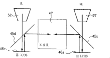
Just, main ripple redness, green light and the blue ray that respectively has a main ripple incides first, second and the 3rd imager 46a, 46b and 46c by being arranged on the one the third and fourth wire grid type PBS 45a, the 45c under first to the 3rd imager 46a, 46b and the 46c and 45d respectively.
First, second is subwave with redness, green light and blue ray by main wave conversion according to picture signal with the 3rd imager 46a, 46b and 46c.The light that becomes subwave reflects to incide the X prism from wire grid type PBS.
At this,, adopted polaroid in order to incide the contrast that the X prism improves light at light.
Just, first, second and the 3rd polaroid (not shown) can be set between X prism 47 and the one the third and fourth wire grid type PBS 45a, the 45c and 45d.
Redness, green and blue ray incide projection lens 48 after X prism 47 synthesizes.The image of being determined by synthetic light is projected onto on the screen.
Figure 17 shows that the optical system before projection lens.
As shown in the figure, the BFL from the projection lens to the imager can change according to the position that is provided with of imager and wire grid type PBS.Along with BFL reduces, when the focusing function of the depth minus hour projection lens of system strengthens.
Sign in above-mentioned situation, the wire grid type PBS of this optical system is set to become the BFL of pitch angle with the minimum optical system with the shorter side of imager, makes all imagers can be arranged on same surface level, thereby simplifies the structure of drive plate.
For the degree of depth that prevents televisor when this optical system is vertically mounted in the televisor increases, be divided into top optical system and lower part.
As Figure 18 and shown in Figure 19, optical system of the present invention comprises two parts of vertical direction and two parts of horizontal direction, thereby reduces the degree of depth of optical system.
Just, Figure 18 is the upward view of Figure 14, be depicted as the structure of optical system in two parts of vertical direction, and Figure 19 is the front view of Figure 14, is depicted as optical system two part-structures in the horizontal direction.
As mentioned above, because 3 template optical systems of the present invention adopt the plate shaped wire grid type PBS of polymeric material, compare the degree of depth that can reduce optical system with traditional optical system.In addition, the BFL of optical system and highly also can reduce to minimum.
It is as follows that reflective lighting optical system of the present invention has plurality of advantages:
Because 3 template optical systems adopt wire grid type PBS, the photoelasticity problem can be resolved.
Can improve and incide projection lens by polarizer is set between X prism and wire grid type PBS The contrast of the light of head.
Because light is by inciding projection lens from the reflection of LCoS plate rather than through wire grid type PBS Therefore astigmatism does not take place in head.
Compare with the traditional optical system with two or three sections light path part, this optical system can Simplify, thereby reduce manufacturing cost; And
Because the wire grid type PBS of this optical system is set to become the inclination angle with the shorter side of imager, Can be so that the BFL of optical system minimize, and all imagers can be arranged on same level Face, thus the degree of depth of television set reduced.
The various modifications and variations that the present invention is done are aobvious and easy for the person skilled in art See. Thereby the present invention will be contained the various modifications and variations that the present invention is done and need only them In the scope and equivalent scope thereof of appended claim.
Claims (11)
1. reflective lighting optical system comprises:
Be arranged on the illuminace component of optical system downside, this illuminace component comprises and is used for alight and makes redness, green and blue ray be divided into its dichronic mirror in different paths separately that described redness, green and blue ray are aimed at from described light irradiation and with polarization member; And
Be arranged on the compound component of optical system upside, this compound component comprises three imagers that are used for phase shift and reflection Red, green and blue ray; Become the wire grid type PBS at a pitch angle with the shorter side of each described imager, be used to transmit by dichronic mirror be divided into its separately the path redness, green and blue ray and be used to reflect redness, green and blue ray by each described imager phase shift and reflection; And the X prism, be used for synthetic redness, green and blue ray so that synthetic light incides projection lens.
2. reflective lighting optical system as claimed in claim 1, it also comprises the polaroid that is arranged between X prism and the wire grid type PBS.
3. reflective lighting optical system as claimed in claim 1, wherein illuminace component also comprises at least one the relay system that is used for compensating each redness, green and blue light path.
4. reflective lighting optical system as claimed in claim 3, wherein said relay system comprises the wire grid type PBS that is used to transmit main ripple or subwave, be used for the modulating the incident light phase place and with P ripple or this modulated light of S wave reflection mirror/wave plate, and be used to modulate the wave plate that is reflected to the light phase on the wire grid type PBS to wire grid type PBS.
5. reflective lighting optical system as claimed in claim 1, wherein wire grid type PBS is a film-type.
6. reflective lighting optical system as claimed in claim 1, wherein said dichronic mirror comprises:
Be used to transmit first dichronic mirror of blue ray and reflection Red and green light; With
Be used to transmit second dichronic mirror of red light and reflection green light.
7. reflective lighting optical system as claimed in claim 1 also comprises the one or more catoptrons that are arranged on each redness, green and blue ray optical path, so that the area of optical system minimizes.
8. reflective lighting optical system comprises:
Be used for alight;
Make from lamp emission and be divided into the dichronic mirror in its different separately path with redness, green and the blue ray that polarization member is aimed at;
Three imagers that are used for phase shift and reflection Red, green and blue ray;
The wire grid type PBS that becomes the pitch angle to be provided with the shorter side of each described imager, be used to transmit by dichronic mirror be divided into its separately the path redness, green and blue ray and be used to reflect redness, green and blue ray by each described imager phase shift and reflection; And
The X prism is used for synthetic reflexing to redness, green and the blue ray on the wire grid type PBS so that synthetic light incides projection lens.
9. reflective lighting optical system as claimed in claim 8 also comprises the polaroid that is arranged between X prism and the wire grid type PBS.
10. reflective lighting optical system as claimed in claim 8, wherein wire grid type PBS is a film-type.
11. reflective lighting optical system as claimed in claim 8, wherein said lamp and dichronic mirror are arranged on described optical system downside, and
Imager, wire grid type PBS and X prism are arranged on described optical system upside.
Applications Claiming Priority (2)
| Application Number | Priority Date | Filing Date | Title |
|---|---|---|---|
| KR1020030030674 | 2003-05-14 | ||
| KR1020030030674A KR100546606B1 (en) | 2003-05-14 | 2003-05-14 | Reflective type lighting optical system |
Publications (2)
| Publication Number | Publication Date |
|---|---|
| CN1550843A CN1550843A (en) | 2004-12-01 |
| CN100412635C true CN100412635C (en) | 2008-08-20 |
Family
ID=33536144
Family Applications (1)
| Application Number | Title | Priority Date | Filing Date |
|---|---|---|---|
| CNB2004100379940A Expired - Fee Related CN100412635C (en) | 2003-05-14 | 2004-05-14 | Reflective lighting optical system |
Country Status (4)
| Country | Link |
|---|---|
| US (1) | US7188955B2 (en) |
| JP (1) | JP4154718B2 (en) |
| KR (1) | KR100546606B1 (en) |
| CN (1) | CN100412635C (en) |
Cited By (1)
| Publication number | Priority date | Publication date | Assignee | Title |
|---|---|---|---|---|
| CN108957921A (en) * | 2017-05-17 | 2018-12-07 | 深圳市光峰光电技术有限公司 | Excitating light strength control system and optical projection system |
Families Citing this family (2)
| Publication number | Priority date | Publication date | Assignee | Title |
|---|---|---|---|---|
| JP4652112B2 (en) * | 2005-04-26 | 2011-03-16 | 富士フイルム株式会社 | Projection display |
| KR100739720B1 (en) * | 2005-08-16 | 2007-07-13 | 삼성전자주식회사 | Color-filterless LCD |
Citations (5)
| Publication number | Priority date | Publication date | Assignee | Title |
|---|---|---|---|---|
| JPH10268235A (en) * | 1997-03-25 | 1998-10-09 | Nikon Corp | Projection display device |
| JPH10319351A (en) * | 1997-05-23 | 1998-12-04 | Nikon Corp | Illuminator for projecting device and projecting device |
| JP2000121997A (en) * | 1998-10-15 | 2000-04-28 | Seiko Epson Corp | Projection type display device |
| JP2000321662A (en) * | 1999-05-12 | 2000-11-24 | Nikon Corp | Color separation optical system and projection type display device having the optical system |
| US6299312B1 (en) * | 2000-02-29 | 2001-10-09 | Samsung Electronics Co., Ltd. | Reflection type projector |
Family Cites Families (18)
| Publication number | Priority date | Publication date | Assignee | Title |
|---|---|---|---|---|
| JP2939237B2 (en) * | 1997-04-09 | 1999-08-25 | 三星電子株式会社 | Reflective projector |
| JP3444521B2 (en) * | 1997-06-20 | 2003-09-08 | シャープ株式会社 | Projection type image display device |
| JPH11142793A (en) * | 1997-11-12 | 1999-05-28 | Victor Co Of Japan Ltd | Projection type display device constituted including polarization beam splitter |
| JP3042460B2 (en) * | 1997-08-26 | 2000-05-15 | 日本ビクター株式会社 | Projection display device |
| DE69819091T2 (en) * | 1997-08-26 | 2004-07-15 | Victor Company of Japan, Ltd., Yokohama | Projection display device with lighting device and polarization beam splitters |
| GB2330678A (en) * | 1997-10-16 | 1999-04-28 | Sharp Kk | Addressing a ferroelectric liquid crystal display |
| JP3973749B2 (en) * | 1998-01-16 | 2007-09-12 | シャープ株式会社 | Projection type image display device |
| JP3490886B2 (en) * | 1998-03-03 | 2004-01-26 | シャープ株式会社 | Projection type image display device |
| JP2000122174A (en) * | 1998-08-11 | 2000-04-28 | Nikon Corp | Projection type display device |
| US6262851B1 (en) * | 2000-01-18 | 2001-07-17 | Hewlett-Packard Co. | Double-pass projection displays with separate polarizers and analyzers |
| JP3347121B2 (en) * | 2000-03-06 | 2002-11-20 | エヌイーシービューテクノロジー株式会社 | Projector device |
| JP4103319B2 (en) * | 2000-10-02 | 2008-06-18 | セイコーエプソン株式会社 | projector |
| US6669343B2 (en) * | 2001-05-31 | 2003-12-30 | Koninklijke Philips Electronics N.V. | Image display system |
| US6857747B2 (en) * | 2001-08-06 | 2005-02-22 | Advanced Digital Optics, Inc. | Color management system |
| JP2004126496A (en) * | 2002-08-05 | 2004-04-22 | Hitachi Ltd | Optical unit and projection type video display device using optical unit |
| JP2004184889A (en) * | 2002-12-06 | 2004-07-02 | Hitachi Ltd | Projection image display device |
| JP2004279705A (en) * | 2003-03-14 | 2004-10-07 | Victor Co Of Japan Ltd | Image display apparatus |
| EP1471746A3 (en) * | 2003-03-31 | 2006-07-12 | Barco N.V. | Projection device and lamp source system for such projection device |
-
2003
- 2003-05-14 KR KR1020030030674A patent/KR100546606B1/en not_active IP Right Cessation
-
2004
- 2004-05-13 US US10/844,451 patent/US7188955B2/en not_active Expired - Fee Related
- 2004-05-13 JP JP2004143803A patent/JP4154718B2/en not_active Expired - Fee Related
- 2004-05-14 CN CNB2004100379940A patent/CN100412635C/en not_active Expired - Fee Related
Patent Citations (5)
| Publication number | Priority date | Publication date | Assignee | Title |
|---|---|---|---|---|
| JPH10268235A (en) * | 1997-03-25 | 1998-10-09 | Nikon Corp | Projection display device |
| JPH10319351A (en) * | 1997-05-23 | 1998-12-04 | Nikon Corp | Illuminator for projecting device and projecting device |
| JP2000121997A (en) * | 1998-10-15 | 2000-04-28 | Seiko Epson Corp | Projection type display device |
| JP2000321662A (en) * | 1999-05-12 | 2000-11-24 | Nikon Corp | Color separation optical system and projection type display device having the optical system |
| US6299312B1 (en) * | 2000-02-29 | 2001-10-09 | Samsung Electronics Co., Ltd. | Reflection type projector |
Cited By (2)
| Publication number | Priority date | Publication date | Assignee | Title |
|---|---|---|---|---|
| CN108957921A (en) * | 2017-05-17 | 2018-12-07 | 深圳市光峰光电技术有限公司 | Excitating light strength control system and optical projection system |
| CN108957921B (en) * | 2017-05-17 | 2021-05-04 | 深圳光峰科技股份有限公司 | Excitation light intensity control system and projection system |
Also Published As
| Publication number | Publication date |
|---|---|
| JP2004341529A (en) | 2004-12-02 |
| KR20040098354A (en) | 2004-11-20 |
| JP4154718B2 (en) | 2008-09-24 |
| US20050001987A1 (en) | 2005-01-06 |
| US7188955B2 (en) | 2007-03-13 |
| CN1550843A (en) | 2004-12-01 |
| KR100546606B1 (en) | 2006-01-26 |
Similar Documents
| Publication | Publication Date | Title |
|---|---|---|
| US6023253A (en) | Image displaying apparatus | |
| US6553168B2 (en) | Projection system utilizing fiber optic illumination | |
| US5185712A (en) | Viewfinder and image display/pickup apparatus using liquid crystal | |
| US6273569B1 (en) | Illuminating optical system and projector | |
| US7646541B2 (en) | Backlighting system for a liquid-crystal display screen and corresponding display device | |
| CN102282502B (en) | Polarization converting color combiner | |
| CN104380177A (en) | Polarization recovery in directional display device | |
| CN102914938B (en) | Projector | |
| JPH04345157A (en) | Projection type display device | |
| CN103189793A (en) | Projector device | |
| TW523609B (en) | Illumination optical system and projector using the same | |
| US6607276B1 (en) | Illuminating optical system and projector | |
| JPH11281930A (en) | Projection display device | |
| CN101893765B (en) | Polarization conversion assembly and single-imager micro projection engine | |
| CN100412635C (en) | Reflective lighting optical system | |
| US6633435B2 (en) | Illumination optical system and projector comprising the same | |
| JP3151771B2 (en) | Image display device | |
| US7161740B2 (en) | Projector | |
| JP2002016934A (en) | Projector | |
| CN101000408A (en) | Total internal reflection prism | |
| US7172287B2 (en) | Reflective illuminating optical system | |
| JP4572457B2 (en) | Optical device and projection display device using the same | |
| KR100354149B1 (en) | Optical System for Head Mount Display | |
| US6512502B2 (en) | Lightvalve projection system in which red, green, and blue image subpixels are projected from two lightvalves and recombined using total reflection prisms | |
| KR0184364B1 (en) | 3d image projector using optical reflective modulator |
Legal Events
| Date | Code | Title | Description |
|---|---|---|---|
| C06 | Publication | ||
| PB01 | Publication | ||
| C10 | Entry into substantive examination | ||
| SE01 | Entry into force of request for substantive examination | ||
| C14 | Grant of patent or utility model | ||
| GR01 | Patent grant | ||
| C17 | Cessation of patent right | ||
| CF01 | Termination of patent right due to non-payment of annual fee |
Granted publication date: 20080820 Termination date: 20100514 |
