Building the Polaron
Check that you have all parts (See parts list on the main page). Check that you know the difference between the various SMD parts that look similar. Optionally clean the PCB and visually check it for damages. In addition to the parts and the teensy you'll need:
- Good, bright light
- A soldering iron with a rather fine tip
- Solder (I use lead solder)
- Diagonal cutters
- Optionally a toothbrush to clean residual flux from the PCB after soldering (don't use for your teeth after that).
- A USB 5-pin Micro-B cable to connect the teensy to your Computer

If you've never soldered before, you shouldn't build the polaron as a first-time project. If you still want to, check Adafruits Guide to Excellent Soldering. The order in which you solder the parts does not matter, but its easier if you start with the smallest, flattest parts first and then move to the bigger parts.
Lets do the LEDs first. Its generally a good idea to start with flat / small parts first and do the bigger parts later, so they don't get in the way. The LEDs are temperature sensitive, its recommended to not heat them up for more than a few seconds at a time. The orientation of the LEDs on the PCB is important, make sure you place it, so that the small triangle on the LED is in the same corner as the small (1mm) extra line of the part diagram on the PCB (top left corner in the image below).

My preferred way to solder these LEDs (and Surface Mount Devices, SMD, in general) is to only solder one connection at the beginning, then correct the position of the part if necessary, and then solder the rest of the connections:
- Place a small dot of solder onto one of the pads (i use the pad with the small 1mm line for this)

- Now place the part and press it down firmly

- Reheat the dot of solder and press the part down. The part is now in place and should stay in position. Correct the position if necessary by reheating the solder, but be careful not to overheat the LED. Make sure the LED is centered exactly with regards to the pads, if you use too much space on one side, it will be hard to solder on the other side.

- When your happy with the position, solder the remaining three connections of the LED
Solder all LEDs like this (I do the circular LEDs first, then the others). With a total of 120 points to solder its easy to forget some, so you might want to check all connections now.
Next solder 14 SMD resistors (270 ohm) on the backside of the PCB. Make sure you get the right components in this step: We need the parts with a small number 2700 printed on top. Use pliers to solder these and the same technique as for the LEDs (dot of solder first, then fix the part onto that dot, then solder the other side)

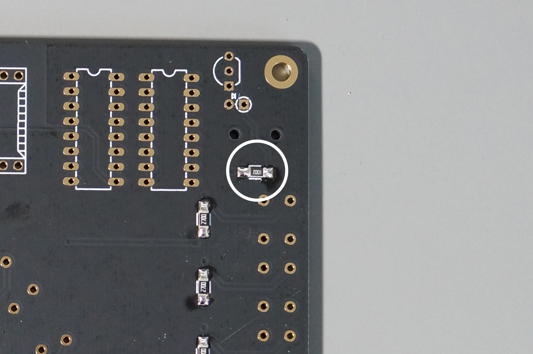
There are two more SMD resistors (10k ohm) needed for the trigger input. One of them is in the upper right corner, with the backside facing you. The other one is in the upper left corner, with the frontside facing you. These two parts are marked with 1002 (don't mix the up with the two capacitors which are slightly thicker and have no printed text on top)

Solder the two SMD Capacitors next to the audio output plug on the top right of the frontside of the PCB.

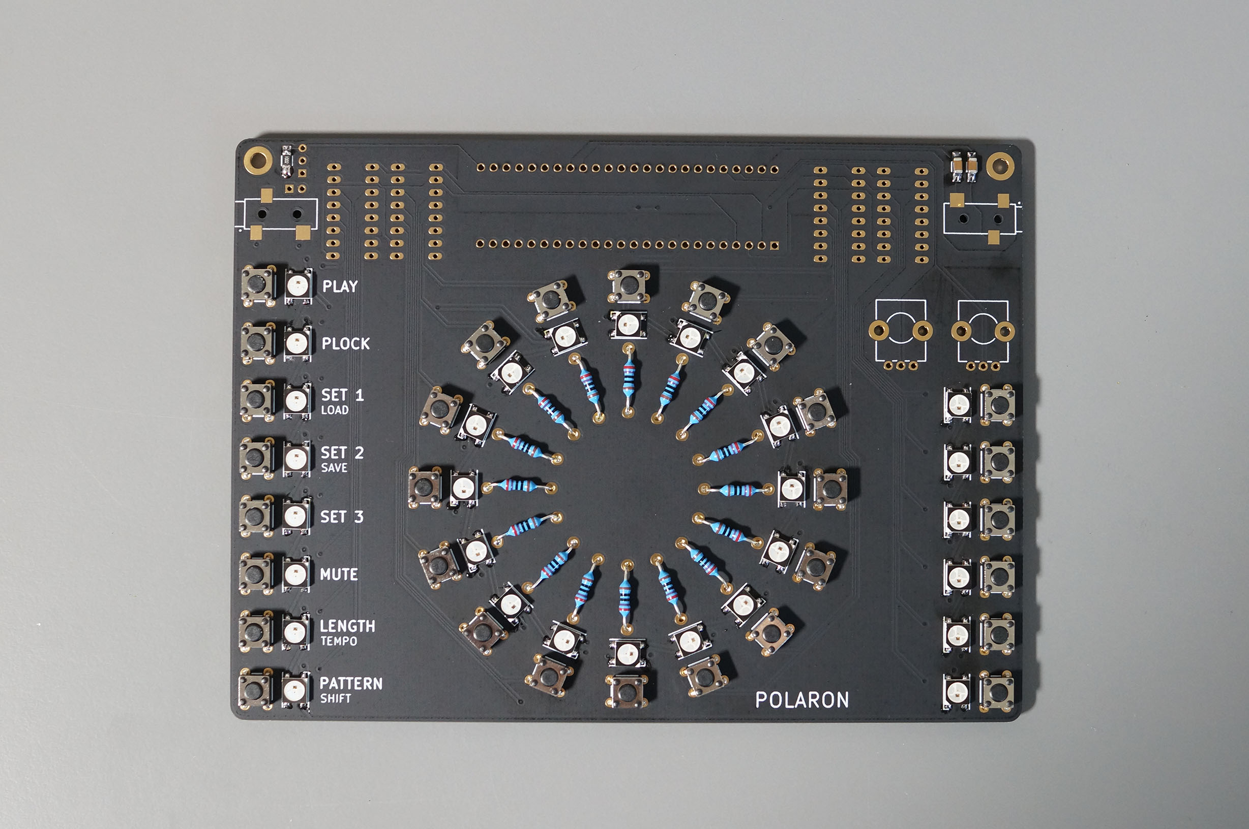
Congrats, you've done the hard part, the rest is peanuts. Lets continue with the 16 through hole resistors that are placed in the center of the circle (270 ohm). PRO TIP: Since we are extremely concerned with aesthetics, make sure to use the same orientation for all resistors (as you most certainly know the orientation of a resistor is irrelevant from an electrical point of view).
- Bend the legs of all resistors
- Place all the resistors into the holes (resistor body is on the frontside of the PCB)
- Turn PCB around while keeping the resistors in place and solder all connections on the backside of the PCB
- Cut of the remainder of the legs on the backside of the PCB

Soldering pushbuttons is rewarding and easy: Enjoy the nice click when you put them in place and solder all legs on the bottom side of the PCB
Not much to write here. The Audio output plug is on the top right, the trigger input on the top left of the PCB frontside. Put the part in place, heat the pad and the plug connector, then apply solder.

Next are the shift registers, which are needed to read out the pushbutton state. Make sure you solder them onto the bottom side of the PCB and not the top. Plus, the orientation needs to be correct, see picture (there is a small marker on one of the short sides of the chip, which needs to match the same marker on the part diagram on the PCB)

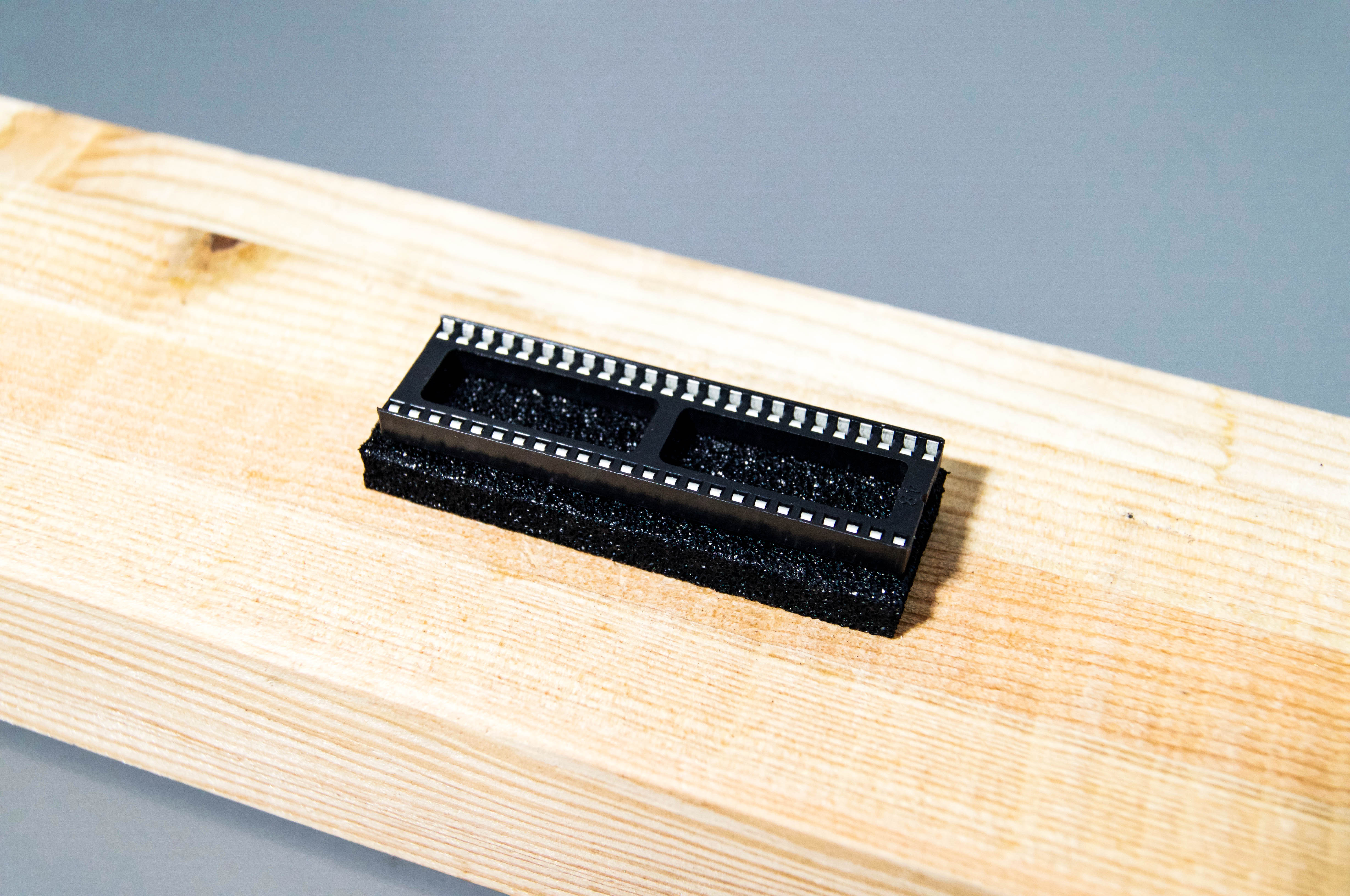
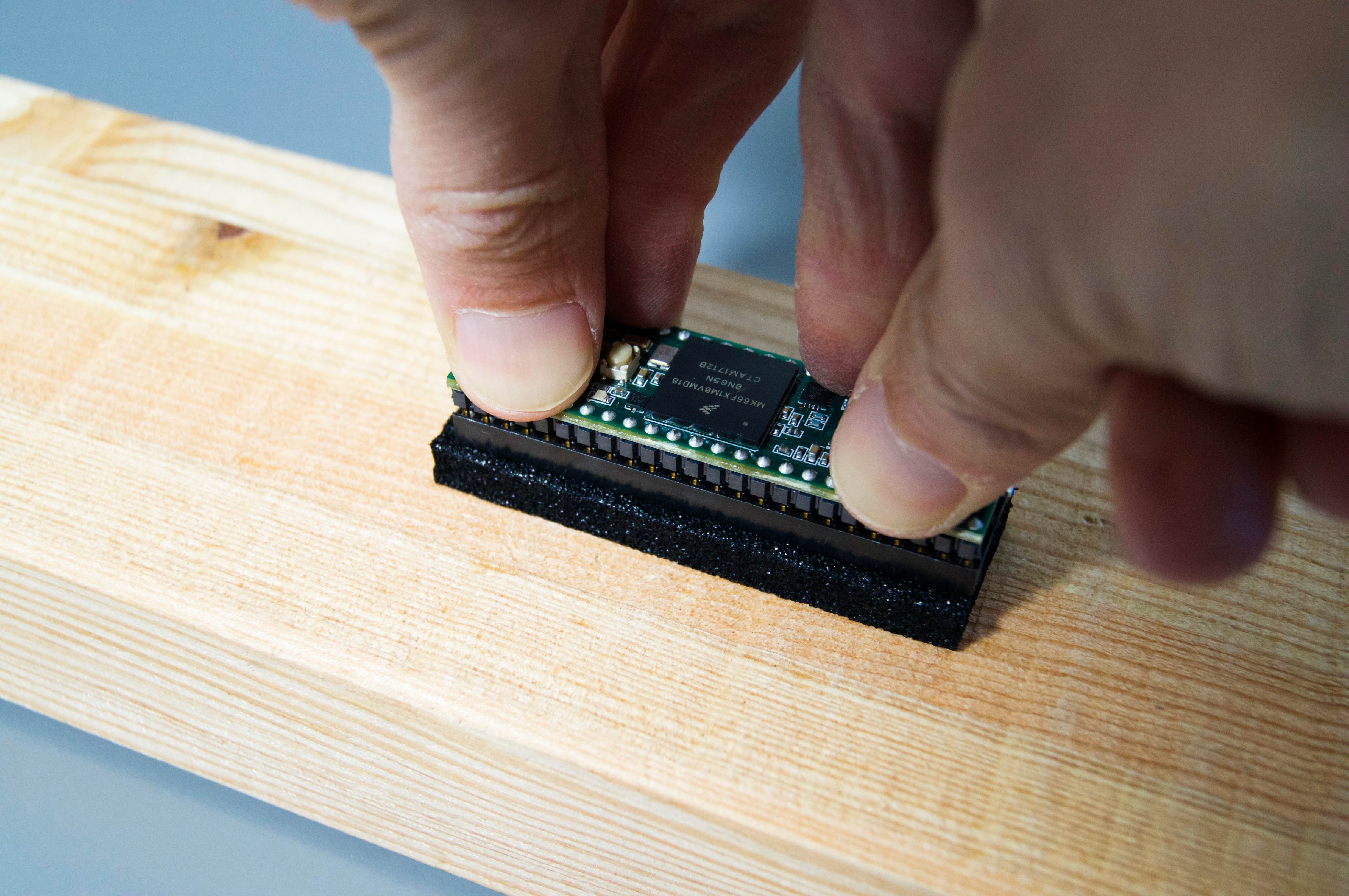
Its not easy to get a 48 pin chip into an IC Socket. It might need some force. I found that its easier to put the Teensy into the IC Socket, before soldering the Socket onto the PCB. For this, put the socket into the black isolation foam that comes with the teensy when you buy it and then press the teensy into the socket by carefully applying force from above.
After that, place the Teensy/Socket onto the BACK of the PCB. Make sure you position it according to the parts diagram on the PCB (there is a marking for the USB Plug and one for the SD card slot as reference). Flip the PCB and solder two diagonally positioned legs of the IC Socket first (eg. the top left and bottom right leg). Before soldering all other connections, make sure that the IC Socket is completely flat on the surface of the PCB (this is very easy to correct, as long as you only have two soldered connections, but almost impossible after you soldered all connections)

Both the transistor (part with a black body and 3 legs) and the diode (part that looks like a resistor with long legs) are soldered on the backside of the PCB. The orientation of these parts is important, be sure to get it right: The transistor part needs to match the part footprint on the PCB. In order for the transistor to fit into the holes, you'll have to bend the outer legs outwards slightly and don't use too much force to put it into the PCB holes. The diode has a black line on one side of its body. This line needs to point in the same direction as the little arrow on the PCB footprint. Bend one leg of the diode before soldering the part (see image).
![]()
Last not least solder the two potentiometers. Thats it, we're almost done. Now is a good time to clean the PCB using a toothbrush (which you should use only for things like this afterwards..). Then use the two small screws to attach the standoffs on the bottom of the PCB.

Well done! Now go wild, have a beer or two, party, share some images and text your friends!

Now its time to Upload the Polaron firmware onto the teensy.