A multi-function digital clock implemented in Verilog HDL, supported by Quartus II and Altera DE1 FPGA.
Clock count, stopwatch, countdown, time setting, reset, pulse and continue, LED display
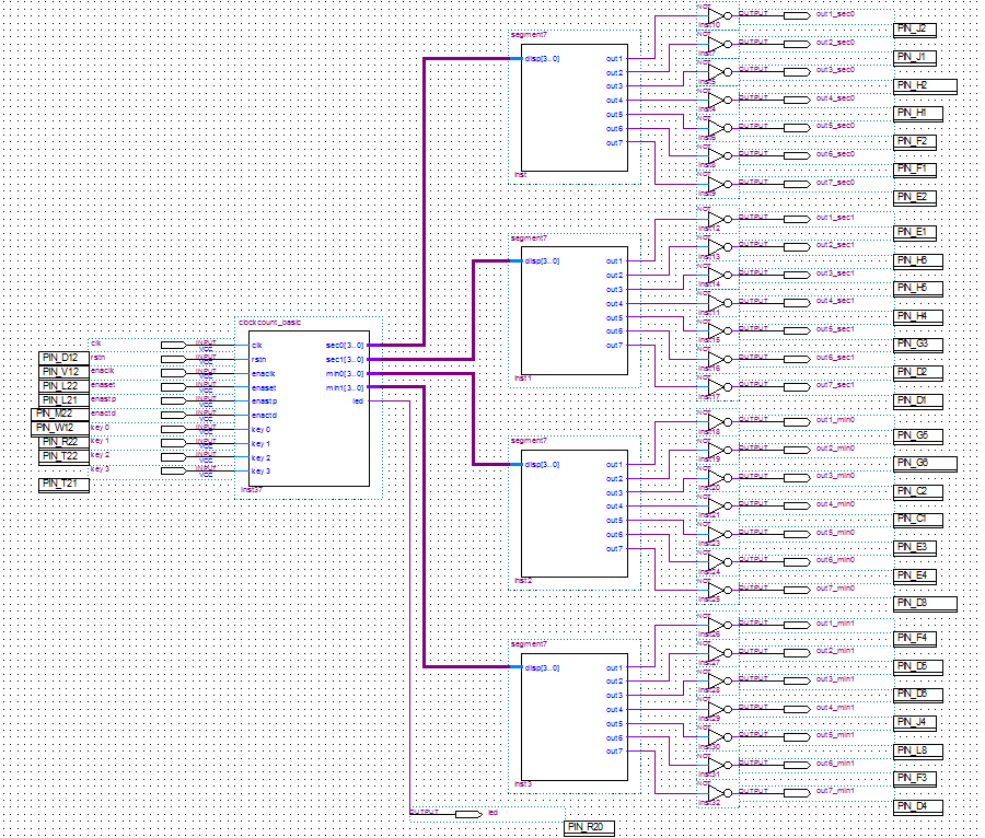
Codes are divided into two parts and they are defining the behaviors and functions of countclock_basic and segment7 respectively.
The part of countclock_basic is composed of several blocks, which count for different functions.
· Frequency division clk: introduce a clock signal of 27000000Hz, which count 1 second each time
· Initial zero status rstn: introduce a negative reset control to zero out the display
· Clock count enaclk: enable clock count function
· Time setting enaset: enable time setting function
· Stopwatch enastp: enable stopwatch function
· Countdown enactd: enable countdown function
· LED: enable LED light LEDR0 when unit digit of second reaches 0.
· Automatic counting: count up the register reg [26:0] count by default under all conditions
The part of segment7 counts for four 7-segment LED display.
· Case disp: assign the seven single segments to the outputs correspondingly
The block diagram consisting of the created symbol from Verilog HDL code is shown below.
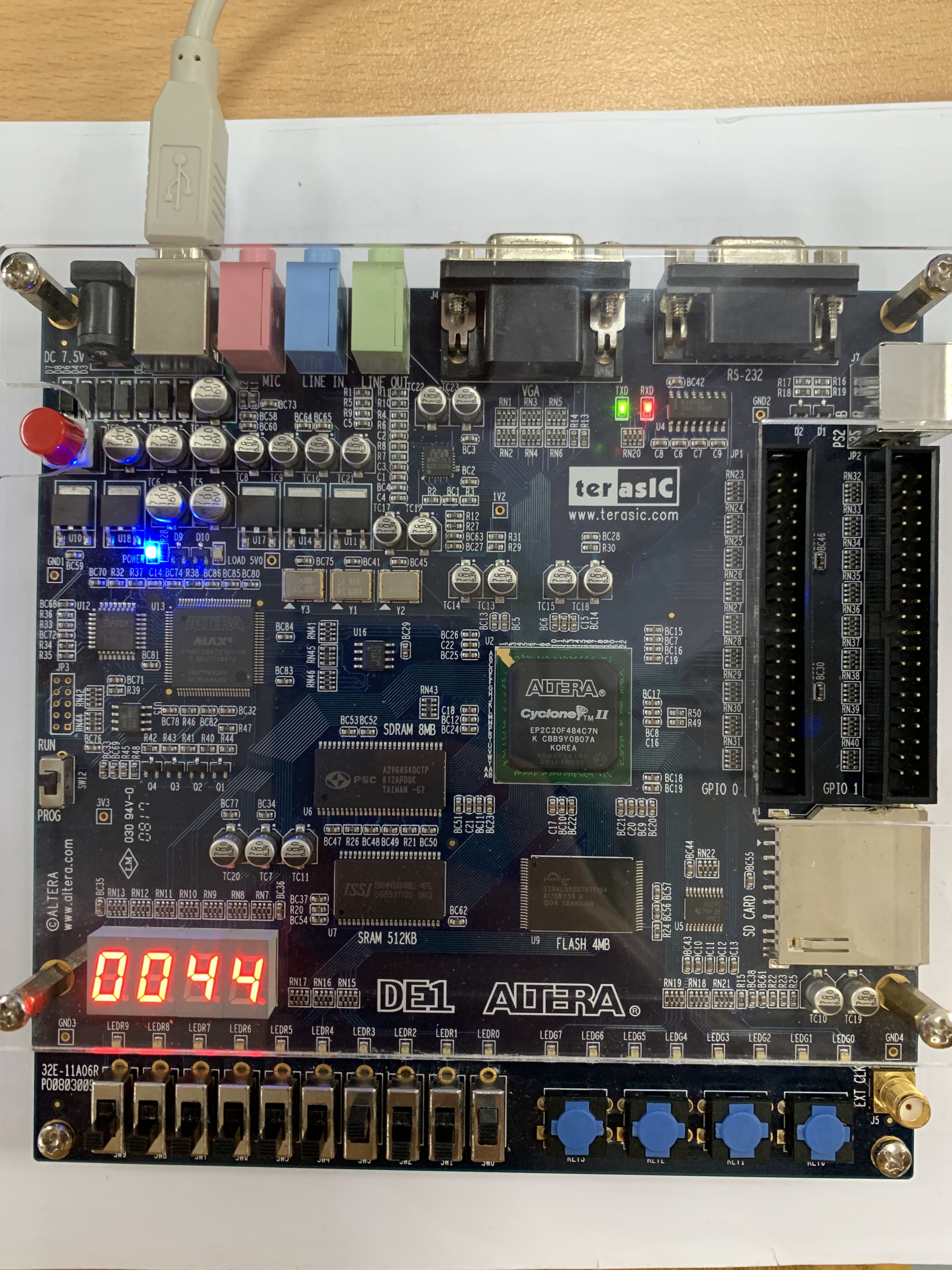
Five toggle switches from SW4 to SW0 and four key buttons from Key3 to Key0 are used, and combinations of inputs give rise to different functions correspondingly. “1” means that the switch is “on” while “0” represents an “off” status of the switch. The toggle switch SW0 is fed by a clock signal clk, and another input rstn representing negative reset is assigned to SW1.
SW4 = 0
SW3 = 1
SW2 = 0
SW1 = 0
SW0 = 1
Turn on the toggle switch SW0 and the clock signal clk is supplied. Since the input enaclk connected to SW3 represents the beginning of clock count, the clock will start
to count upon turning on the switch SW3.
In this part, the clock count can also be reset, pulsed and continued. Turn off switch SW0 at clock counting status and the clock count will pulse due to the cutoff of clock signal. Turn it on again will make the count continue. In addition, turning off switch SW3 will lead to a reset and the display will show “0000”.
The time setting function is supported by five toggle switches and four key buttons. By turning on toggle switch SW3 and SW1, the LED displays are reset and the time can be set.
SW4 = 0
SW3 = 1
SW2 = 0
SW1 = 1
SW0 = 0
The four 7-segment LED displays are controlled by four key buttons respectively. By pressing buttons one by one, the corresponding 7-segment LED will enter a loop from 0 to 9. Therefore, the time setting can be implemented.
Key3 = up
Key2 = up
Key1 = up
Key0 = up SW4 = 0
SW3 = 1
SW2 = 1
SW1 = 0
SW0 = 1 The stopwatch function also requires the supply of clk signal controlled by SW0. Since the input enastp connected to SW2 represents the beginning of stopwatch, the stopwatch will start upon turning on the switch SW3 and SW2.
The stopwatch can also be reset, pulsed and continued. Turn off switch SW0, the stopwatch will pulse and it continues by turning it on again. Turning on switch SW3 will lead to a reset.
SW4 = 1
SW3 = 1
SW2 = 0
SW1 = 0
SW0 = 1
The countdown is enabled by turning on the enactd switch, which is SW4. It works only when non-zero numbers are displayed by four 7-segment LEDs. The counting accuracy is designed to be tenth of second.

