In the basic operation mode. the pulse generator is triggered, then creates a single square pulse of some width after a certain delay. The trigger can be from an external source, the computer, or a frequency synthesizer builtin to the T564. Each channel is individually configurable with different delays (time from the trigger to the rising edge of the pulse), pulse widths (time from the rising edge to the falling edge of the pulse), polarities (whether channel is active-high or active-low, referred to as “positive” and “negative”, respectively). Each channel can also be disabled if it is not in use.
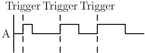
For example, the following timing diagram:
Would be generated by the following channel settings:
A: width: 1ms
   delay: 0ms
   polarity: positive
B: width: 10ms
   delay: 5ms
   polarity: positive
C: disabled
D: width: 20ms
   delay: 15ms
   polarity: negative
And would be programmed using the following code:
import T564
from T564 import ureg

t = T564("/dev/T564") # Replace with whatever serial port the T564 is connected to

t.a.width = 1*ureg.ms
t.a.delay = 0*ureg.ms
t.a.polarity = "pos"
t.a.enabled = True

t.b.width = 10*ureg.ms
t.b.delay = 5*ureg.ms
t.b.polarity = "pos"
t.b.enabled = True

t.c.enabled = False

t.d.width = 20*ureg.ms
t.d.delay = 15*ureg.ms
t.d.polarity = "neg"
t.d.enabled = TruePower is provided by a +12V AC adapter that plugs into the wall. The green power LED will turn on when power is available to the T564. Communications to the computer are through a standard RS232 serial communications through a 2.5mm phone jack. A 2.5mm-to-D9 cable is included, which should be connected to a D9 (male)-to-USB adapter to connect the device to a computer.
Along the front of the device, there are six SMB connectors. The left two are labelled GATE and TRIG. When GATE mode is being used, triggers are only accepted if the GATE input is active. TRIG is used for external triggering. The remaining four SMB connectors are the four T564 outputs, labelled A through D. Note that the four outputs are too close together for a rigid SMB-BNC converter to be used. Instead, use ones with a short length of cable between the two ends.
The back of the device contains the power connector, the RS232 jack, and an SMB connector labelled CLOCK. This can be configured as either an output or input so that the clock can be synced with the rest of the experiment.
Before initializing the T564, we need to find the serial port it’s
attached to. To get a list of all of them, run find /dev -name 'ttyUSB*'. After determining the serial port use the following code to
set up the T564:
import T564
from T564 import ureg

t = T564.T564("/dev/ttyUSB1")
Throughout the rest of this document, I will refer to the T564 object
as t. Each channel is controlled by an attribute of the T564 object;
channel A is t.a, channel B is t.b, and so on. t.channels is a
tuple containing all four channels, for convenience. All four channels
are disabled by default, so remember to set the enabled property of
any channel you want to use to True.
The T564 library uses the module Pint (https://pint.readthedocs.io/)
to make handling the vastly different timescales the T564 can operate
on easier. Basic usage is simple: just multiply a scalar by
ureg.<unit> to create a quantity with a unit. Units work as you
would expect: ureg.ms (or ureg.milliseconds) is milliseconds,
ureg.Hz is hertz, and ureg.cm is centimetres. Use the method to to
convert between units and the magnitude attribute to get the value
without a unit:
x = 3*ureg.us # x = 3 microseconds
y = x.to(ureg.ns) # y = 3000 nanoseconds
x.magnitude # 3
y.magnitude # 3000
See the Pint documentation for more on how it works.
If you don’t want to use Pint, frequencies are assumed to be in hertz and times are assumed to be in nanoseconds, except for the trigger period which is assumed to be in seconds.
The library currently includes support for software triggers and
frequency-based triggers. To use software triggers, run
t.trigger_software() to switch to software trigger mode, then run
t.trigger_fire() whenever you wish to have the T564 fire pulses.
To use triggers at regular intervals, switch to frequency-based
triggers with t.trigger_synthesizer(). This mode uses the T564’s
internal frequency synthesizer to fire triggers at a consistent
rate. The maximum frequency that can be set is 16MHz. The trigger rate
can be set either by frequency or by period, so that the following two
lines do the same thing:
t.frequency = 1*ureg.kHz
t.period = 1*ureg.msThe T564 can output many spaced pulses from one trigger using train
mode. This is controlled by using two properties: t.train_count and
t.train_spacing. t.train_count is the number of pulses to output
per trigger. Set this to 1 to disable train mode. t.train_spacing is
the time between the end of one set of pulses and the start of the
next, rounded to the nearest 20ns. The minimum train spacing is 80ns
greater than the time between the first rising edge of and last
falling edge of a set of pulses. If you attempt to set the train
spacing to a value that is too small, it will be silently set to the
minimum value.
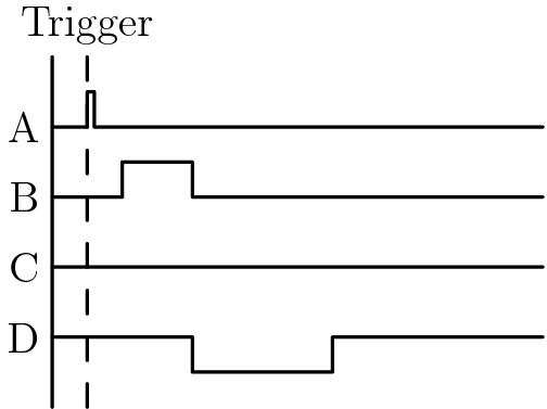
Pulse trains are only enabled on a channel if the delay is at least 20ns. If you wish to have a channel excluded from a pulse train, set its delay to some value below 20ns.
For example, to produce the following timing diagram:
Use the following code:
t.a.width = 30*ureg.ms
t.a.delay = 0*ureg.ms # Disable pulse train on this channel
t.a.enabled = True

t.b.width = 5*ureg.ms
t.b.delay = 20*ureg.ns # Enable pulse train on this channel
t.b.enabled = True

t.train_count = 4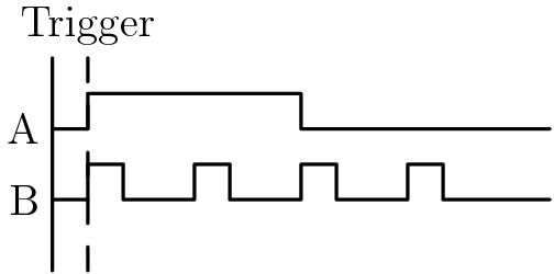
t.train_spacing = 10*ureg.msThe T564’s frame mode lets it cycle through channel settings, switching on each trigger. For example, the following frames:
Frame 1: A width = 10ms
Frame 2: A width = 20ms
Frame 3: A width = 30ms
Would result in channel A rotating between 10ms, 20ms, and 30ms pulse widths on each trigger.
A frame includes the all the settings for each channel and train
settings. To create a frame, change the settings as appropriate then
run t.frame_save(). To create the frames in the earlier example:
t.a.width = 10*ureg.ms
t.a.enabled = True
t.frame_save()

t.a.width = 20*ureg.ms
t.frame_save()

t.a.width = 30*ureg.ms
t.frame_save()
To clear saved frames, use t.frame_clear(). t.frame_loops
controls the number of times frame mode will loop through the saved
frames. If you set it to 0, the frames will loop forever. Once the
frames are all set up, run t.frame_start() to begin running through
the frames. If you want to interrupt the frames at any time, use
t.frame_stop(). Once the frames are done looping, triggers will be
ignored until you run t.frame_stop().
The full code to set up the example above is therefore:
t.frame_clear() # Clear whatever frames were already in memory

# Frame 1
t.a.width = 10*ureg.ms
t.a.enabled = True
t.frame_save()

# Frame 2 - any unchanged settings carry over between frames, so A is still enabled
t.a.width = 20*ureg.ms
t.frame_save()

# Frame 3
t.a.width = 30*ureg.ms
t.frame_save()

t.frame_loops = 5
t.frame_start()
Which will result in the following timing diagram, repeated five times: