The repo shows how to establish VPC (Virtual Private ☁️) network-peering in Google Cloud Platform (GCP 🚀) and use the Nginx as a reverse proxy to interact with the server in the established network. In this demonstration, we'll use three VPCs that are located in three different geographical regions, each hosting a server (virtual machine) containing a single service. We'll connect the VPCs according to the following diagram (Figure 1)), establishing communication between an API server and a database via a proxy service.
Fig.1 - A schematic representation of the demo
the following table is a summary of the services that will be created in this demonstration. Throughout the tutorial, we'll refer to this table.
| sl | VPC Name | VPC Location | VPC Subnet Name | IPv4 Network | VM Name | VM IP Address | Container name | Exposed Port |
|---|---|---|---|---|---|---|---|---|
| 1 | vpc-api | us east1 | vpc-api-subnet | 10.10.0.0/24 | vm-api | 10.10.0.2 | api | 3000 |
| 2 | vpc-db | us west1 | vpc-db-subnet | 192.168.0.0/24 | vm-db | 192.168.0.2 | db | 3306 |
| 3 | vpc-proxy | us central1 | vpc-proxy-subnet | 172.16.0.0/24 | vm-proxy | 172.16.0.2 | reverse-proxy | 80 |
Note If you're following along, throughout the demonstration, unless otherwise mentioned, keep every settings as default while creating any services in Google Cloud Platform (GCP) for the purpose of reproducibility.
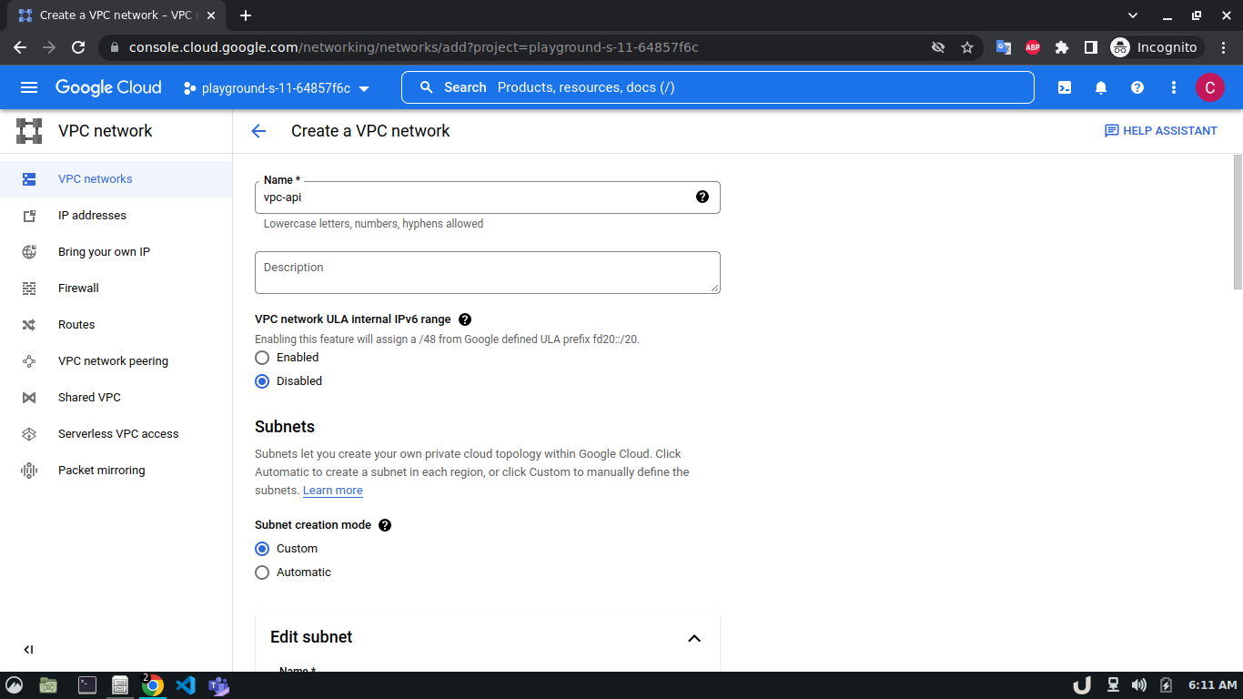
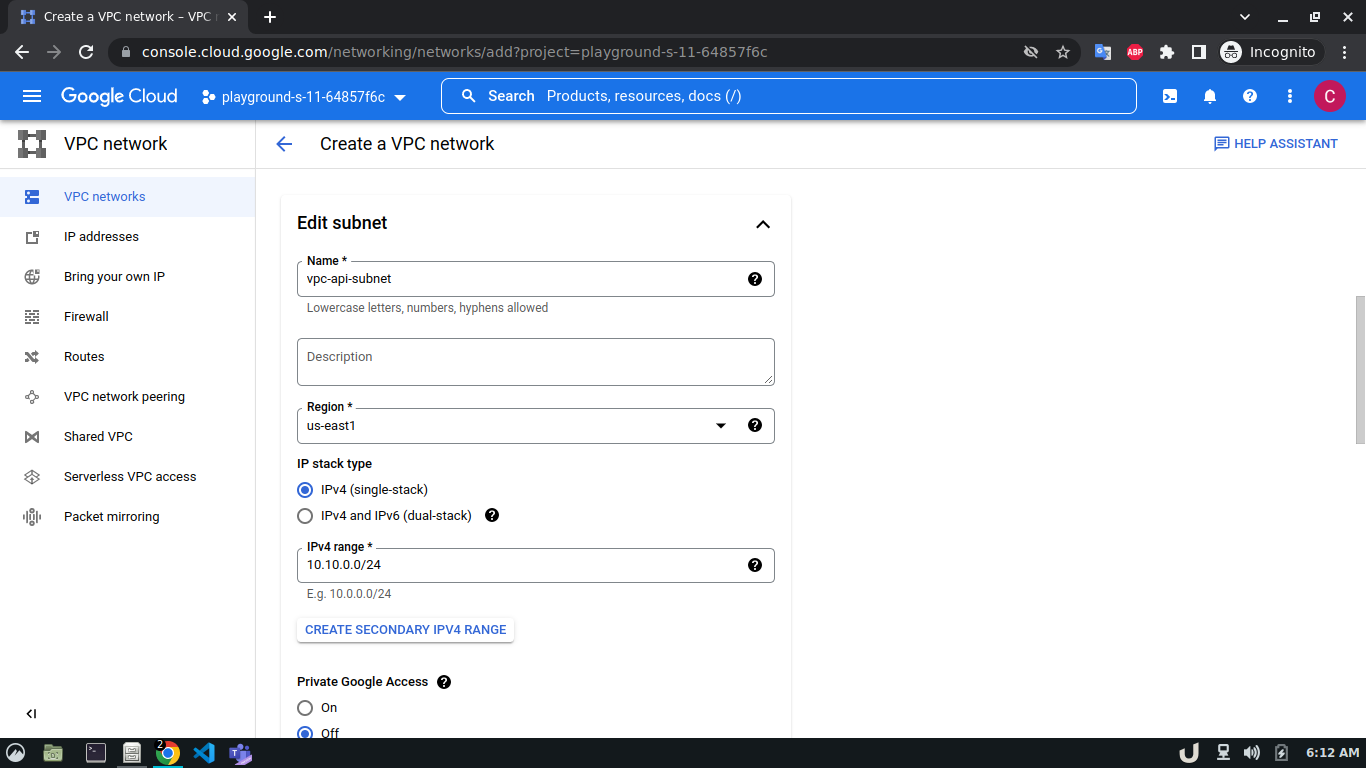
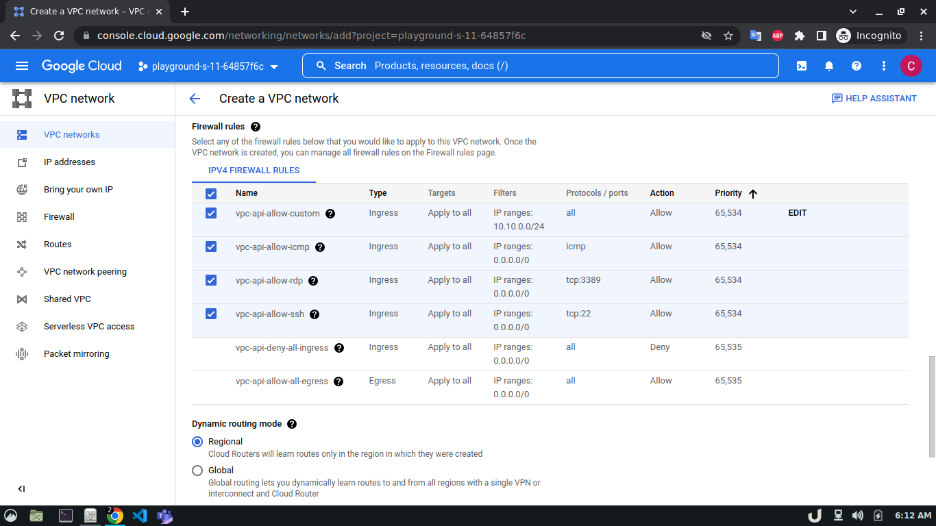
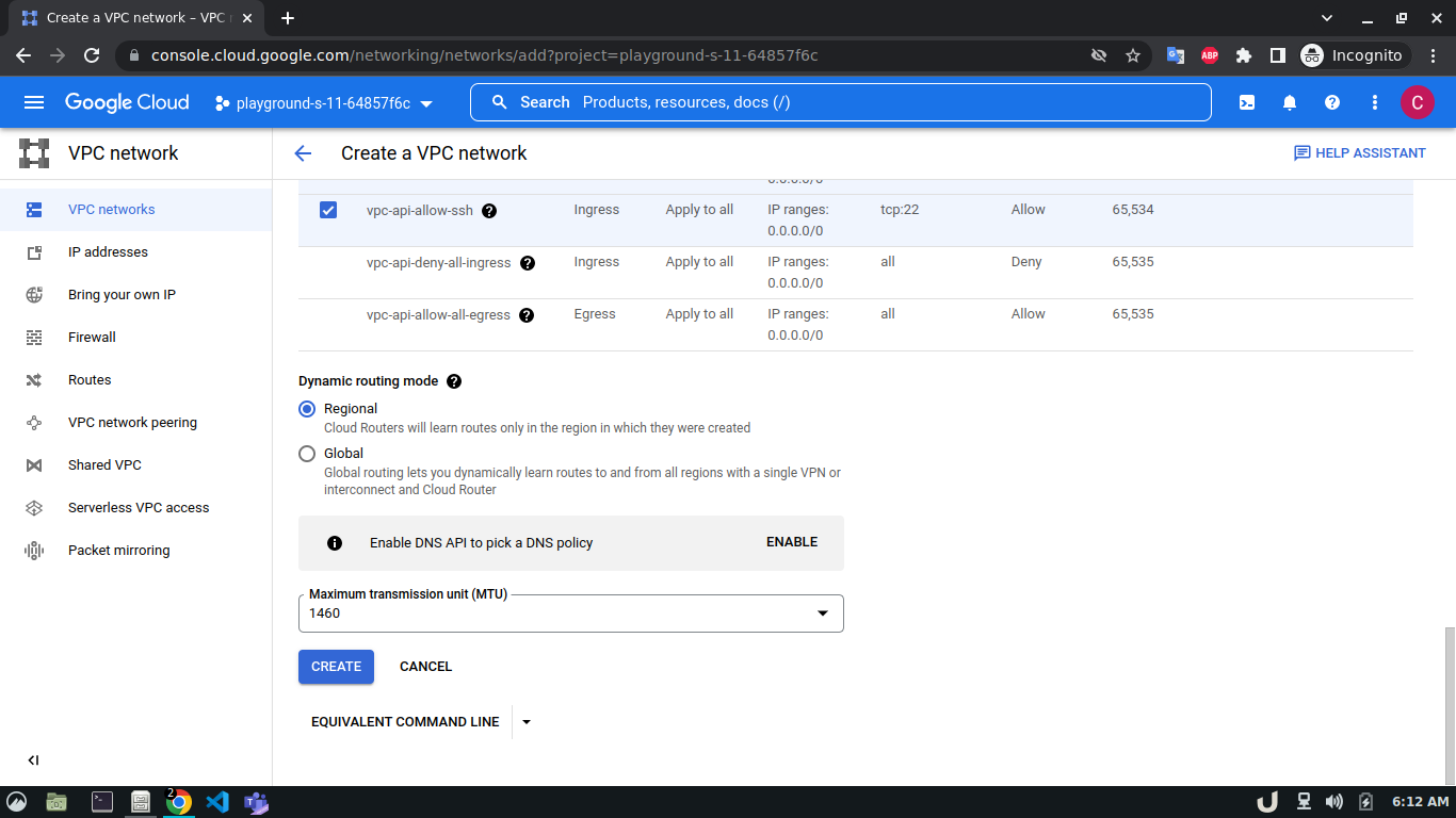
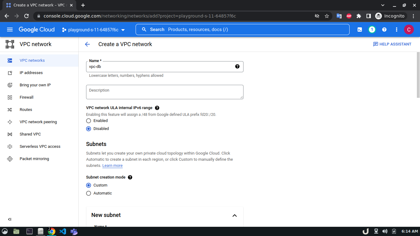
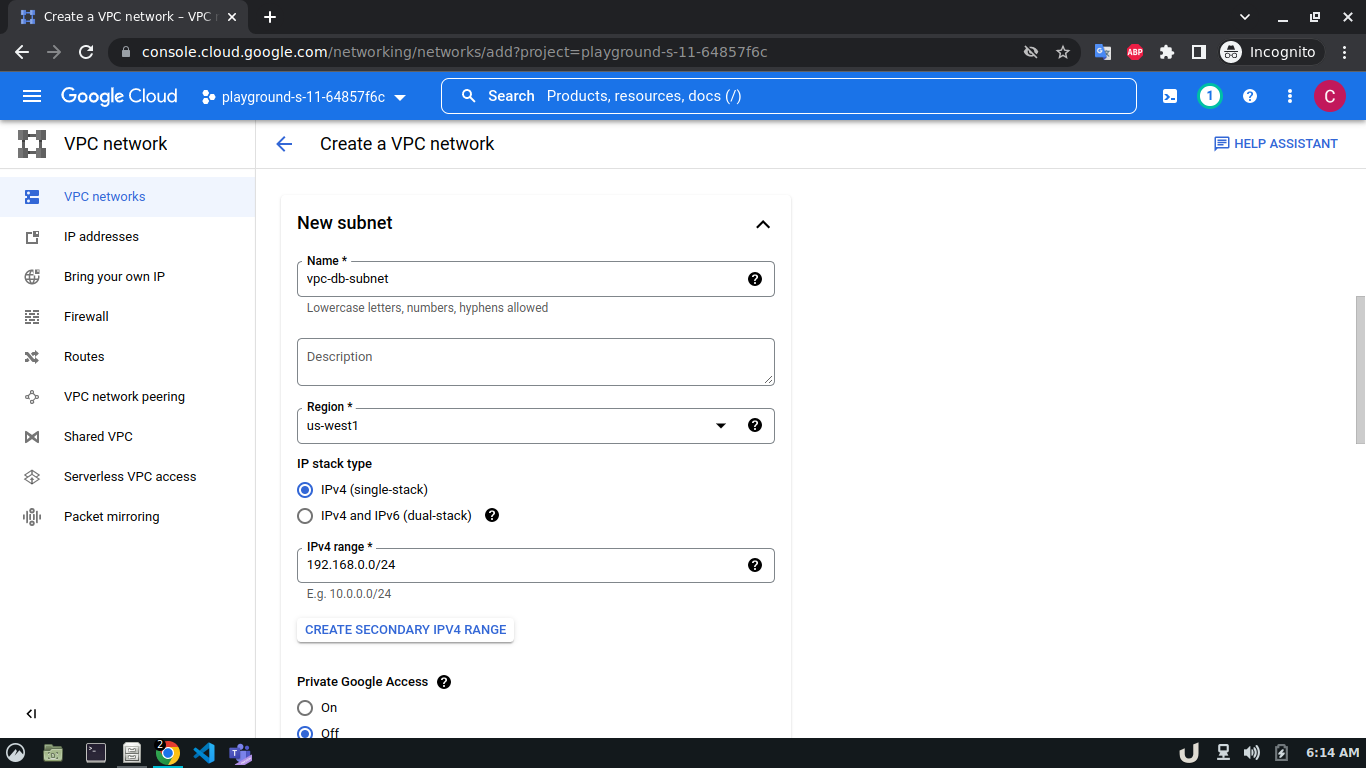
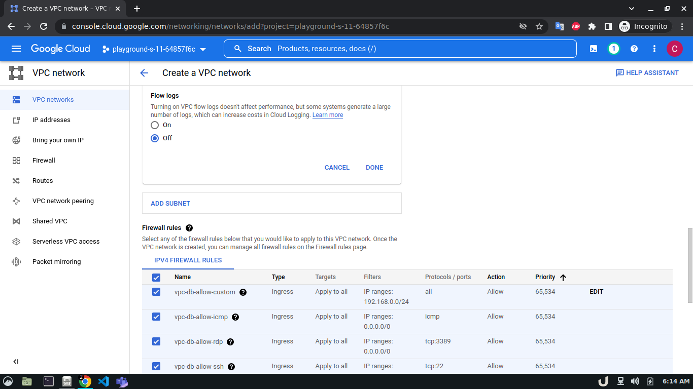
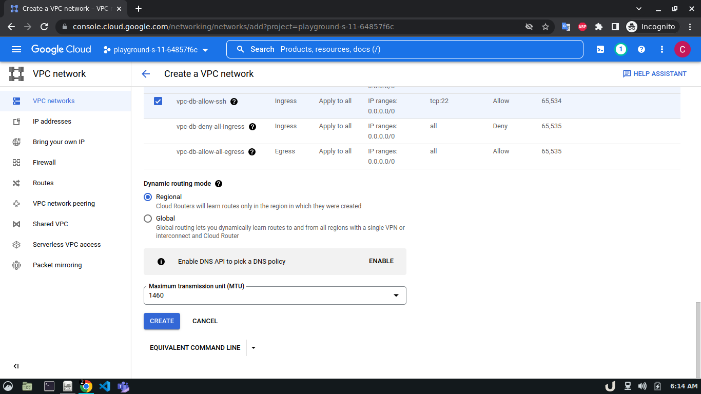
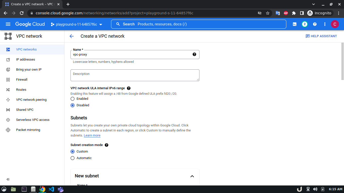
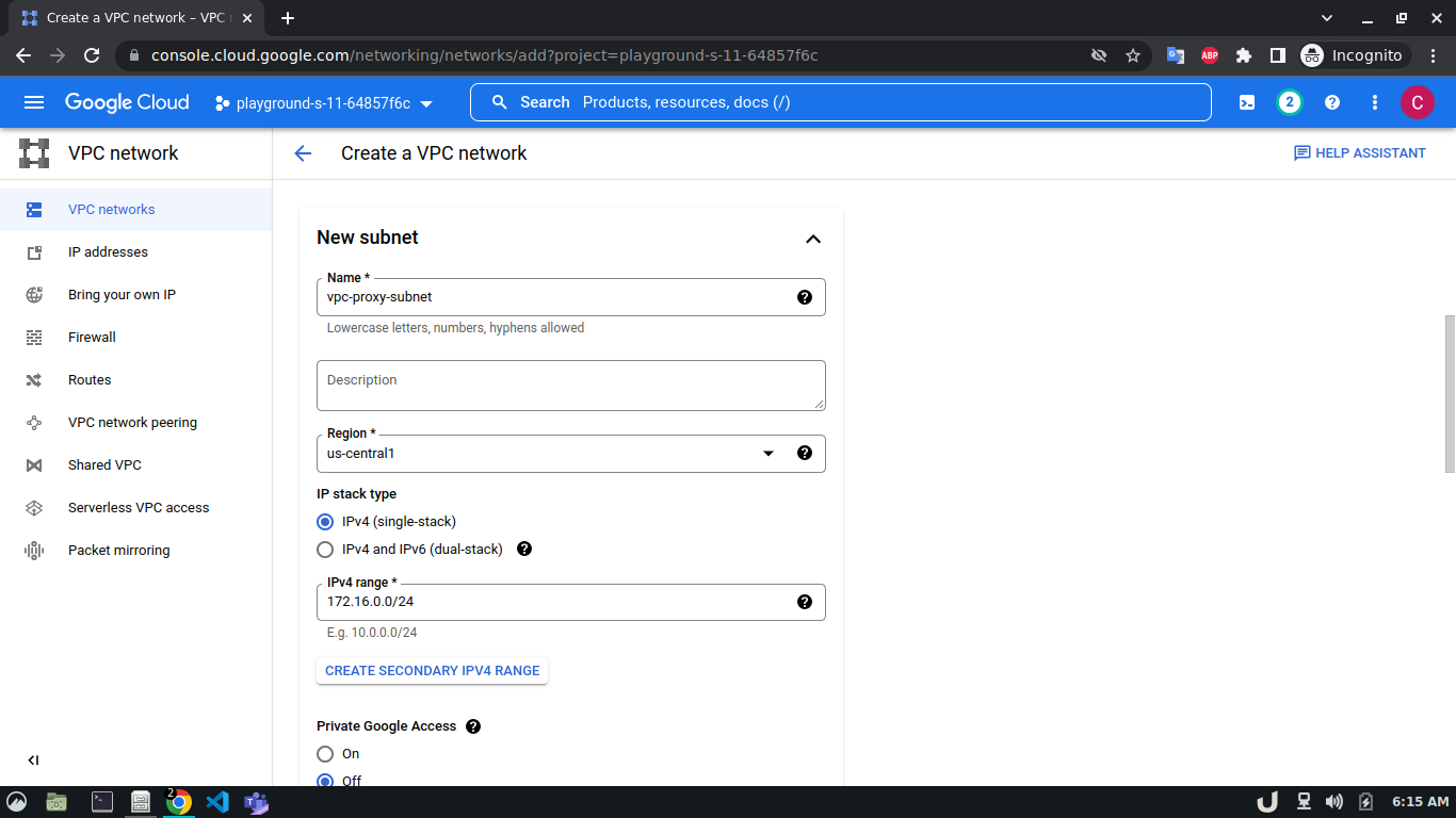
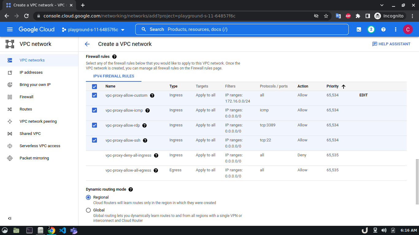
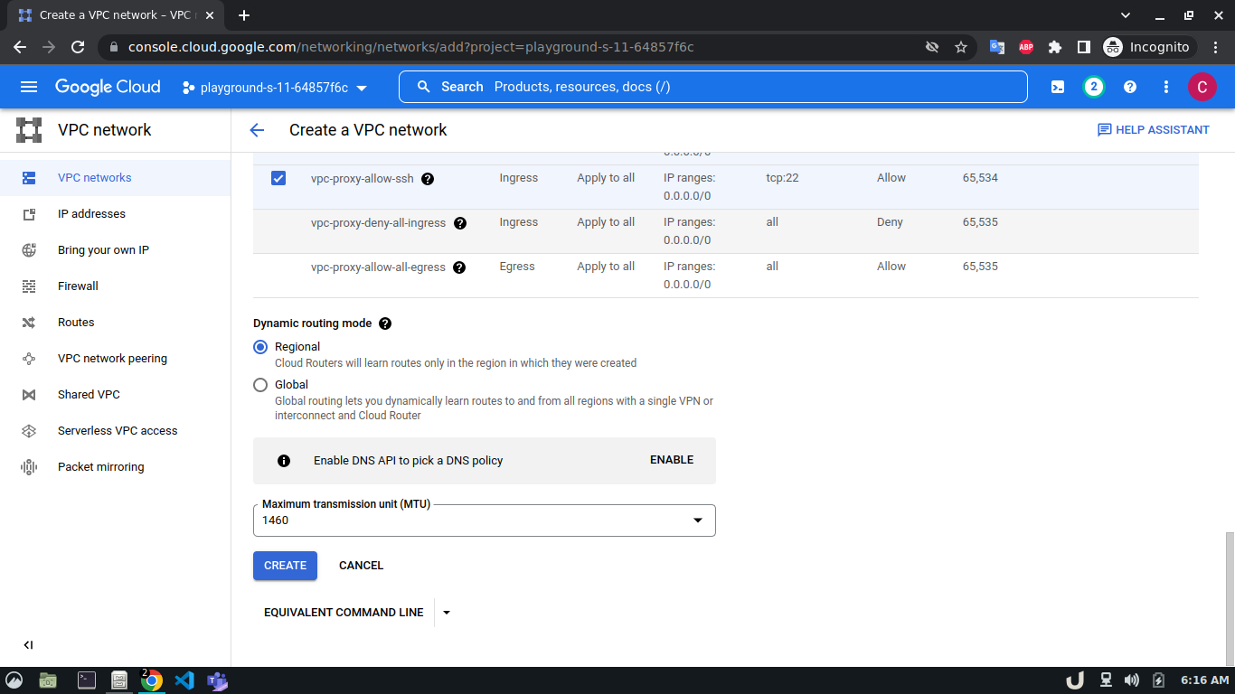
Let's start by creating our VPC. To create a VPC you need to do the following step:- Go to the VPC network from the menu and select VPC networks followed by Create VPC network. Now, we need to provide a name for the VPC. After that, we'll create a new subnet, providing the name of the subnet, region, and IPv4 range in CIDR notation. We'll allow the default firewall rules and click on the create button to finish off the VPC creation process.
We'll create 3 VPCs for our demo. They are vpc-api, vpc-db and vpc-proxy. The subnet name will follow this pattern <VPC_NAME>-subnet and the IPv4 range will be according to Table 1.
The step-by-step process for creating each VPC is shown below,
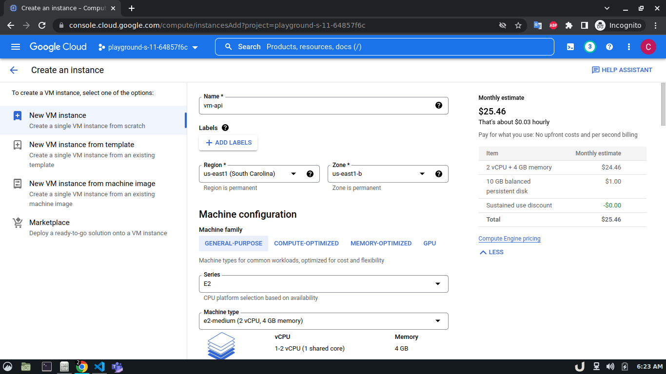
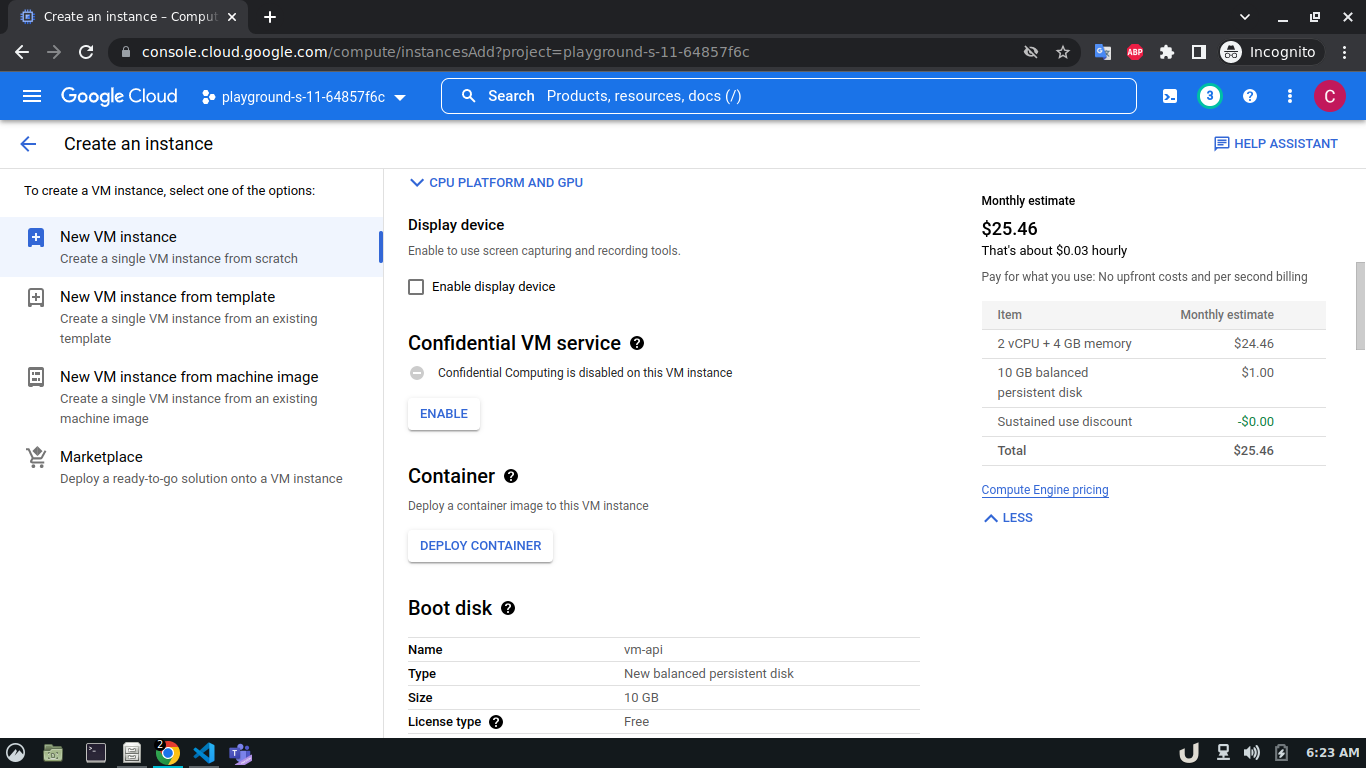
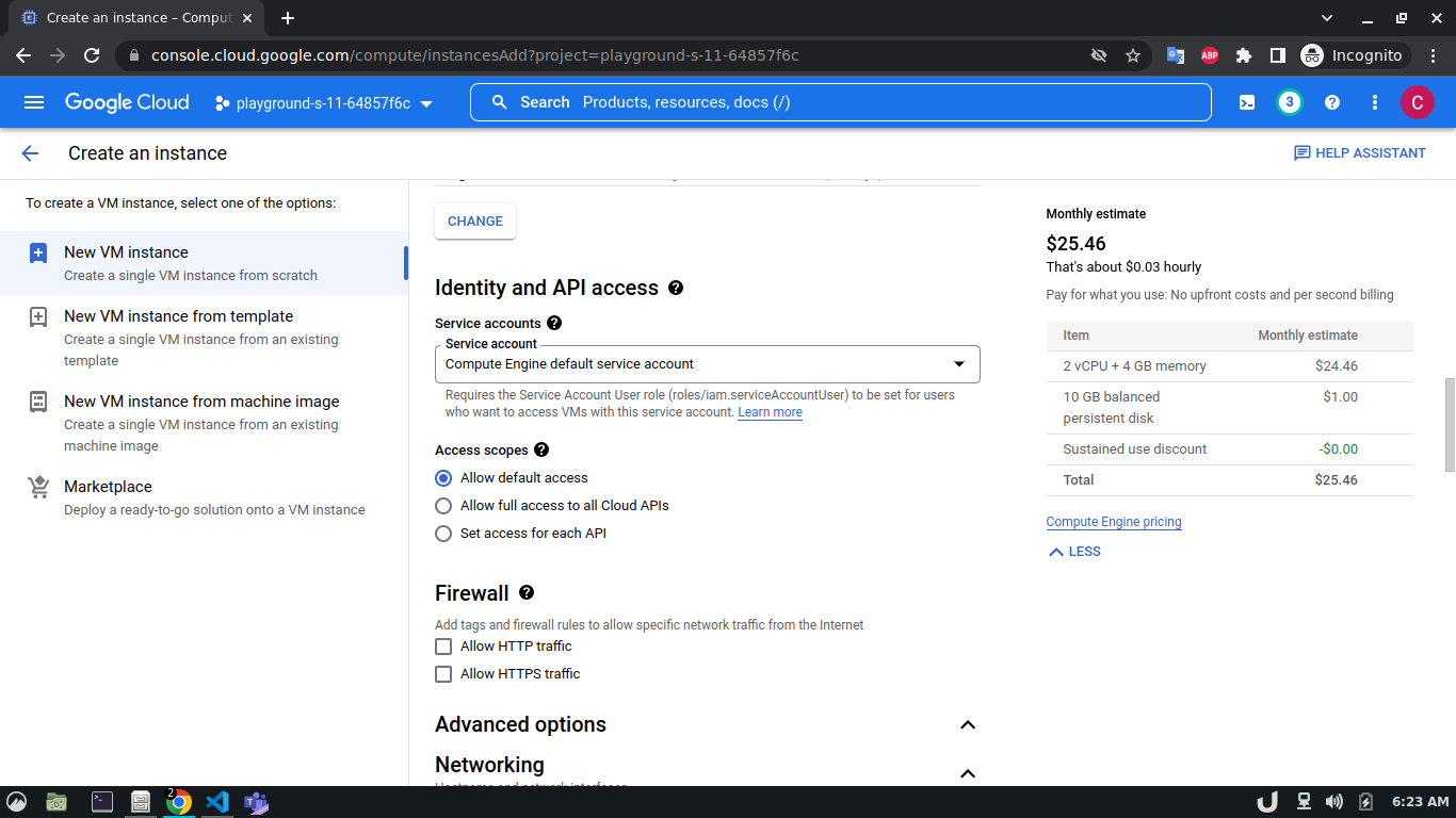
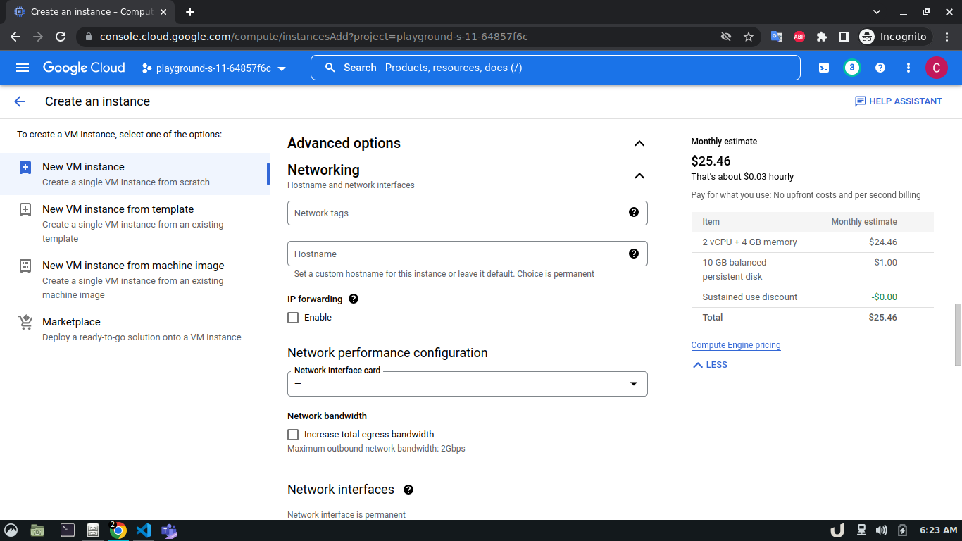
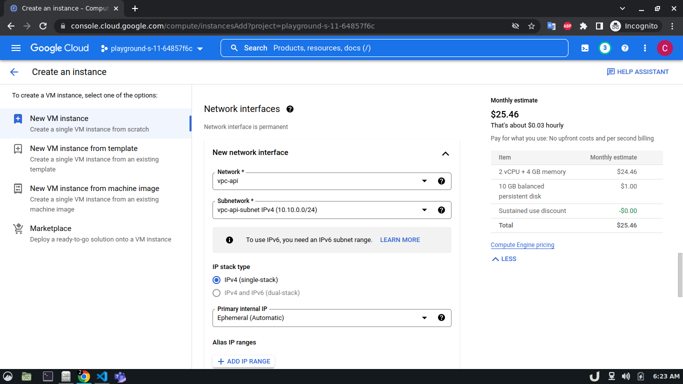
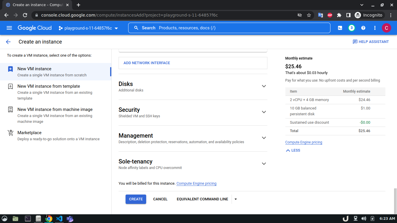
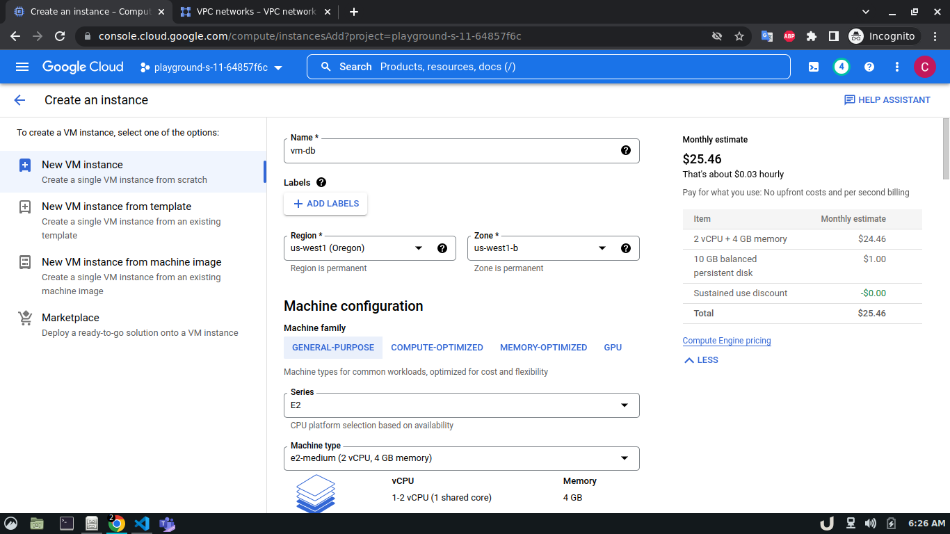
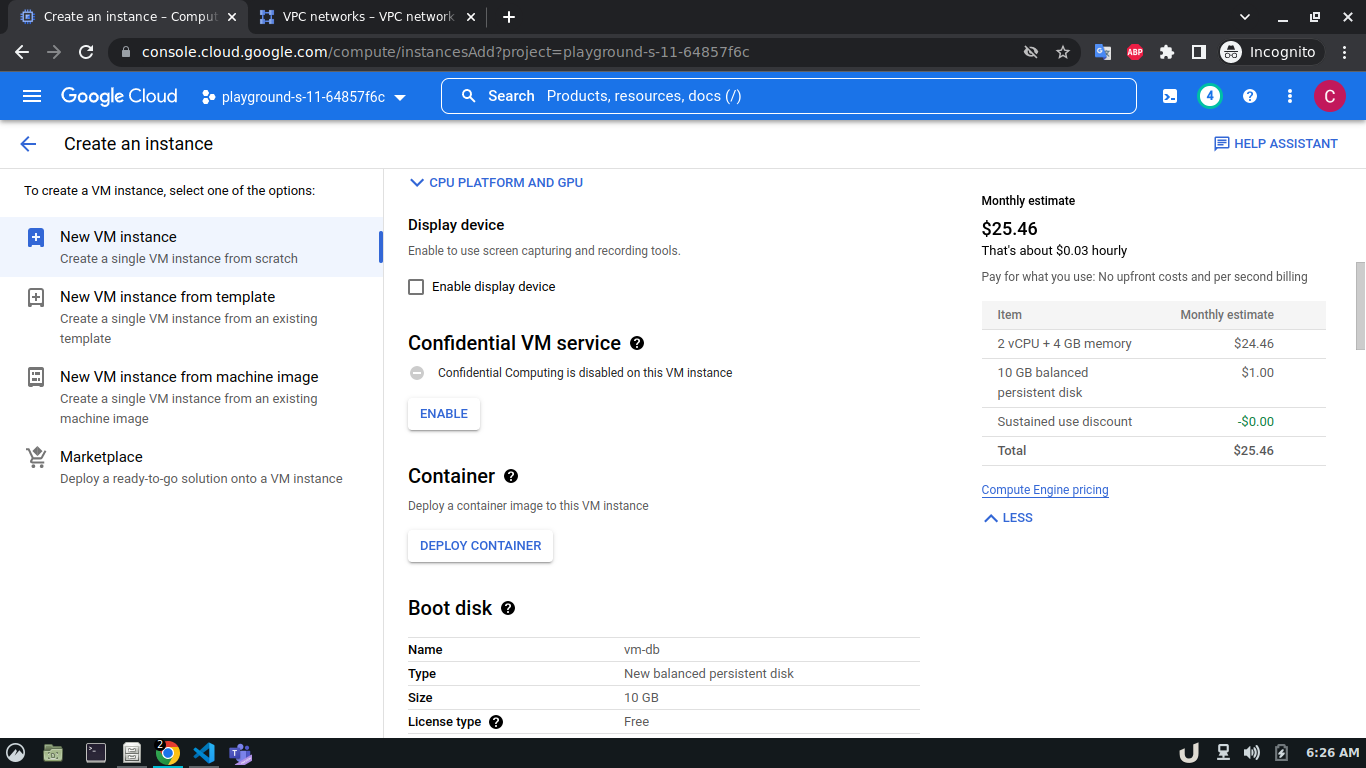
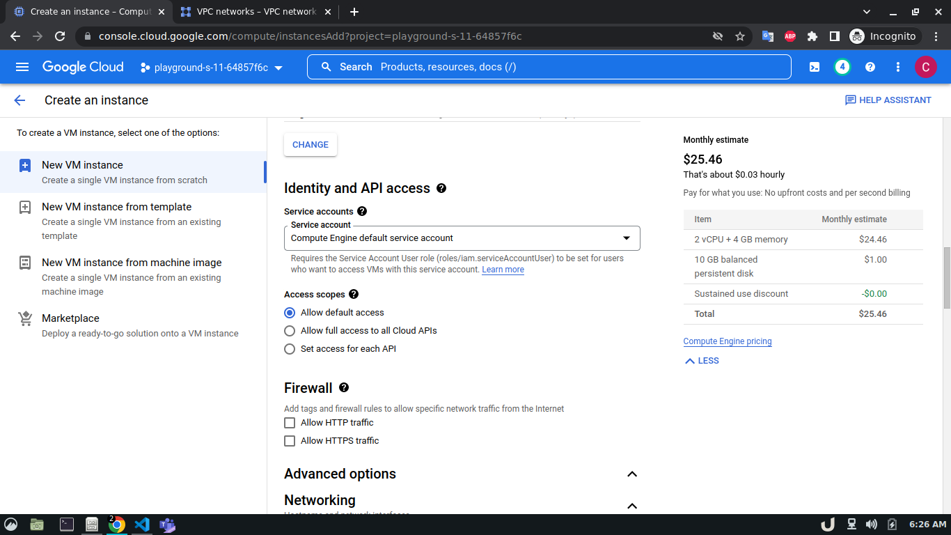
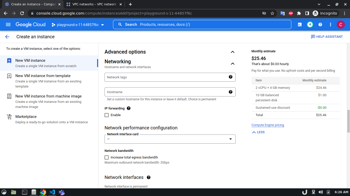
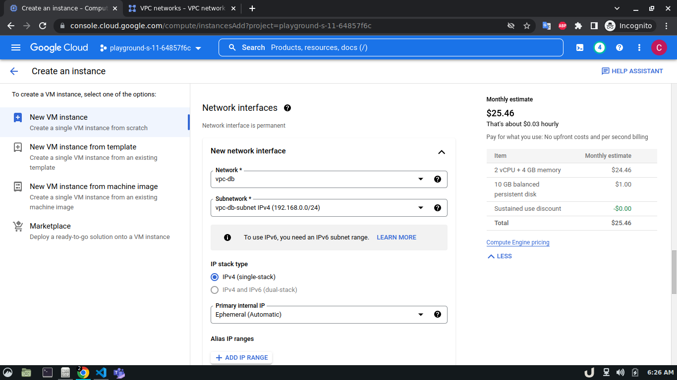
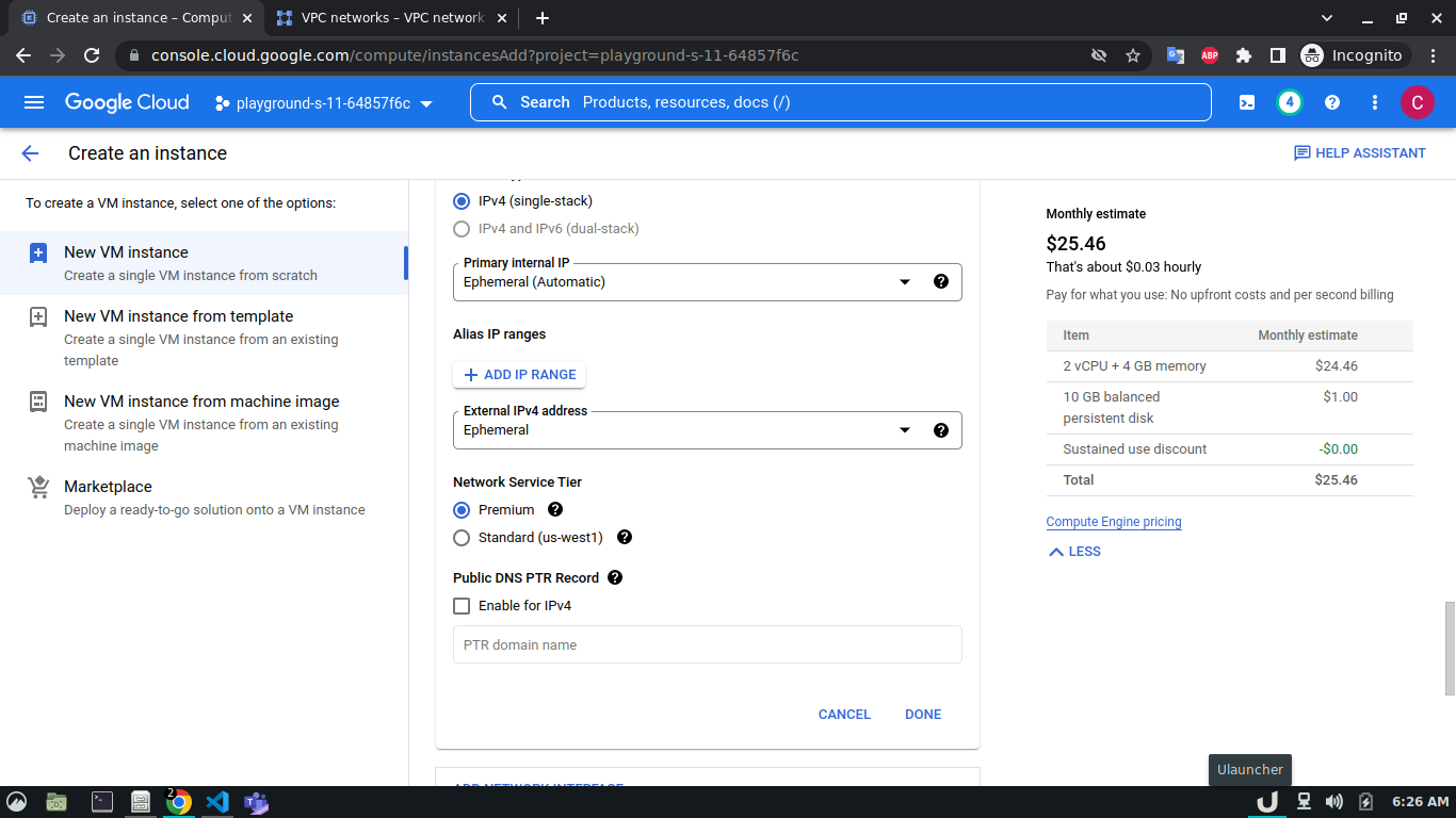
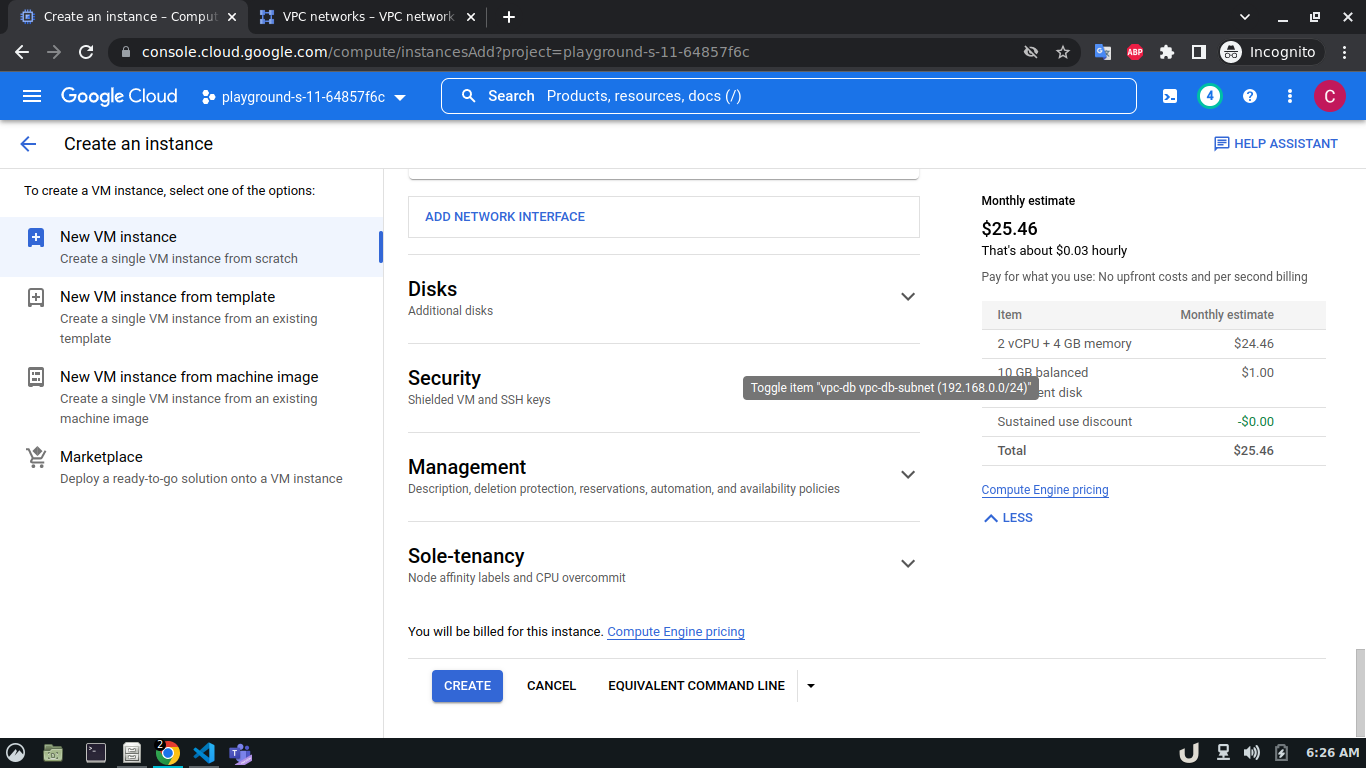
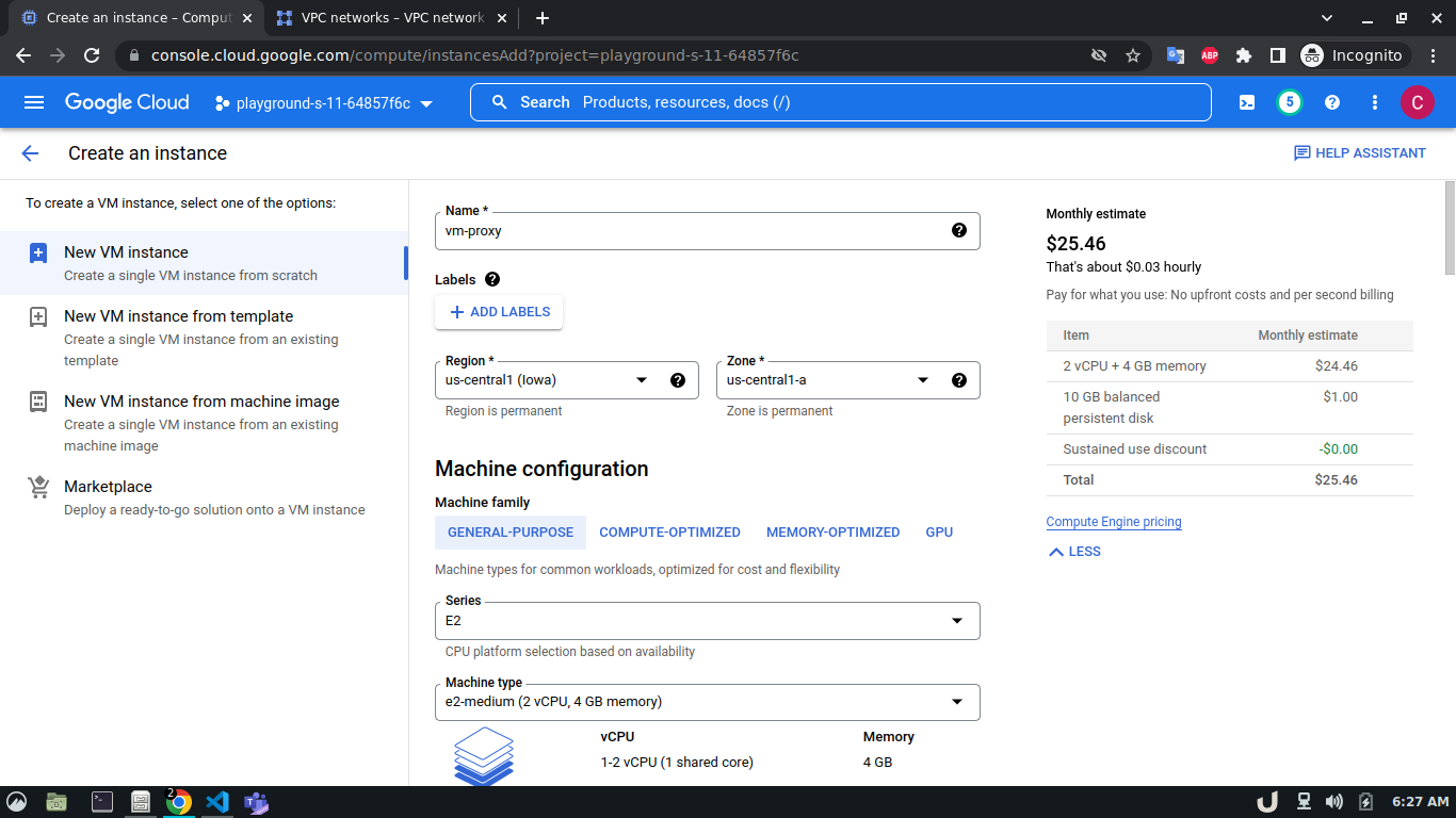
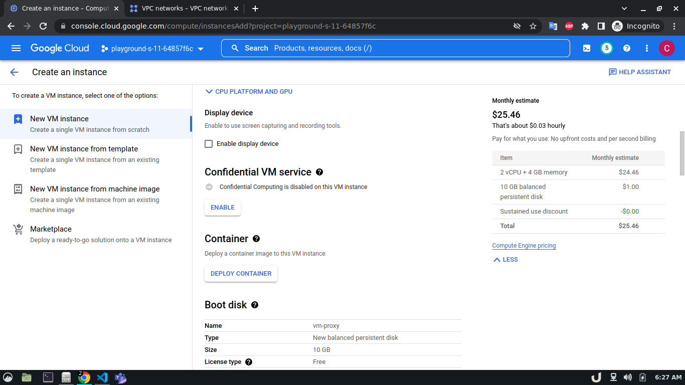
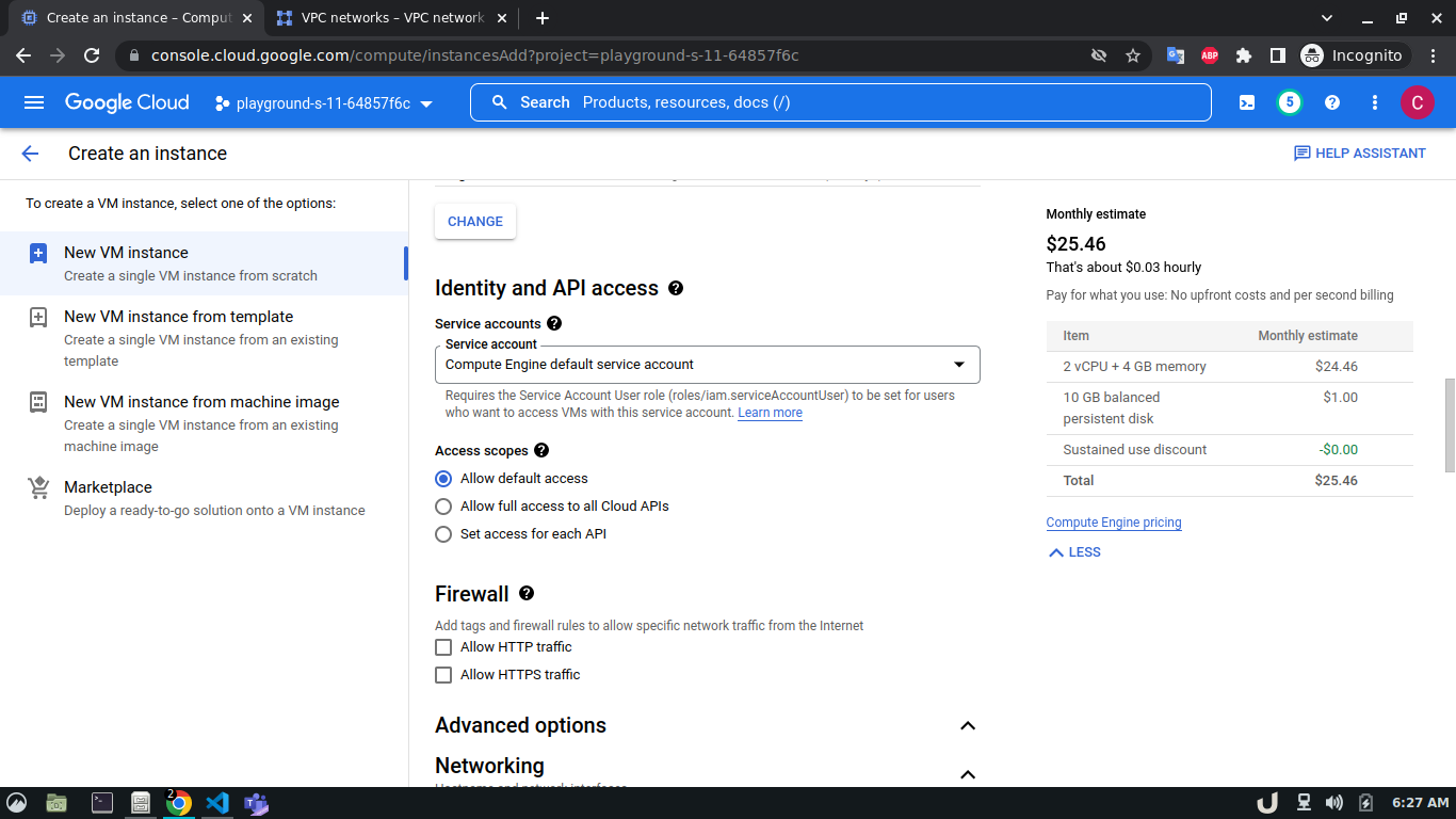
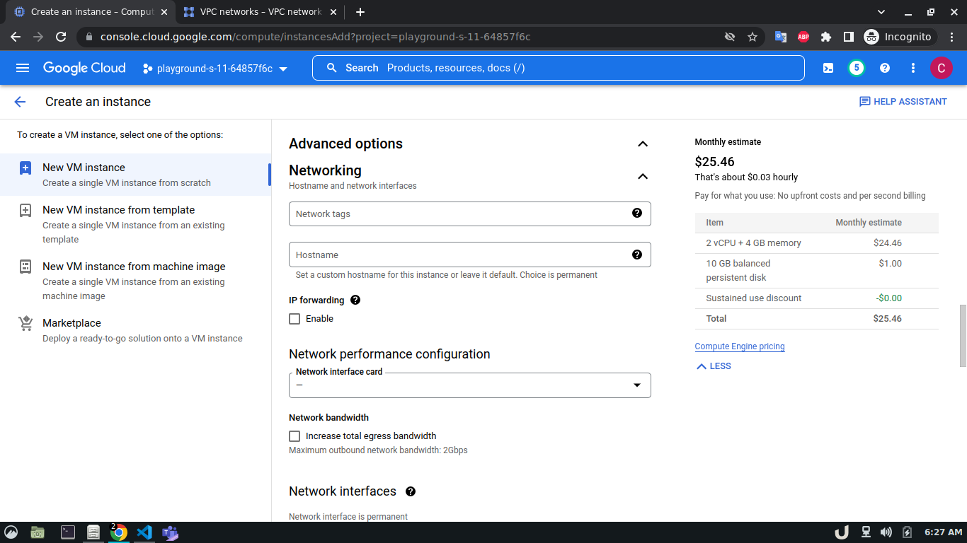
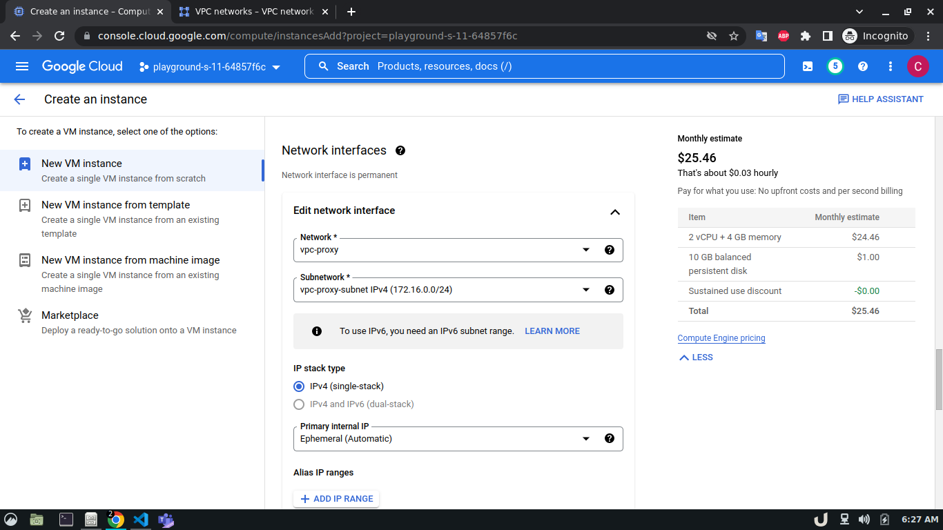
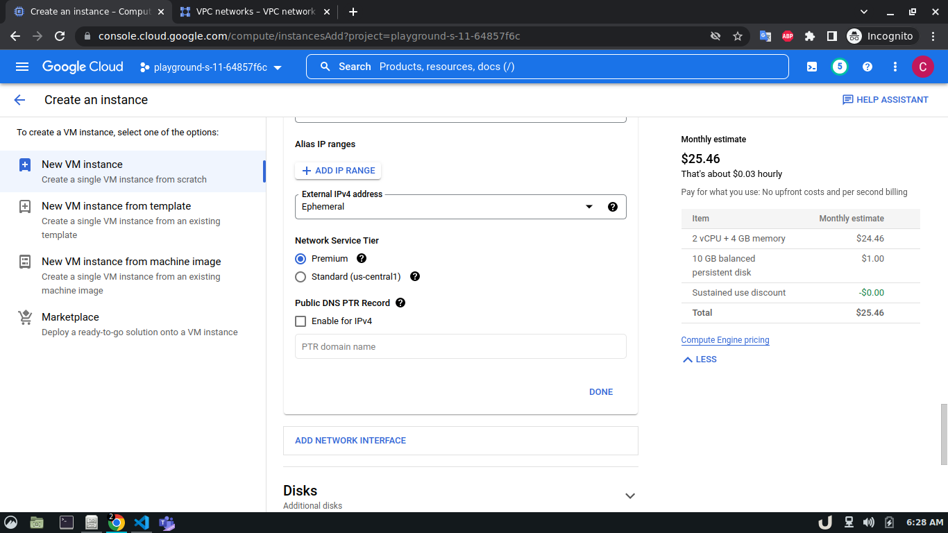
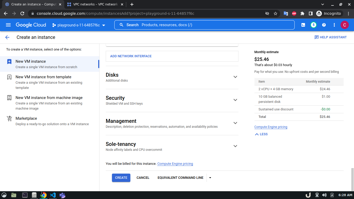
Once we're done with creating VPC, we'll start creating our servers (VM). To create VM, go to Compute Engine from the menu, select VM Instances followed by Create Instance. We'll provide a name, select a region and stick to the default zone of that region. Then go to Networking settings of the Advanced options. Now, specify a new network interface by selecting a network and a subnetwork. Here, we'll create a 3 VM for each VPC namely vm-api, vm-proxy and vm-db. The region will be the same as the corresponding VPC of each VM. The network and subnetwork will be the name of the VPC and its subnet for each VM respectively. We'll complete the process by clicking on the create button.
The step-by-step process for creating each VM is shown below,
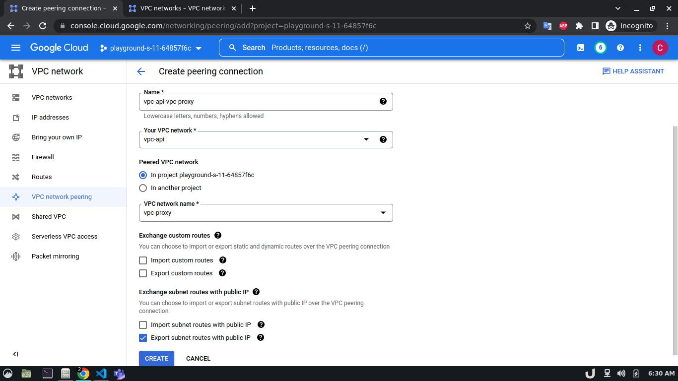
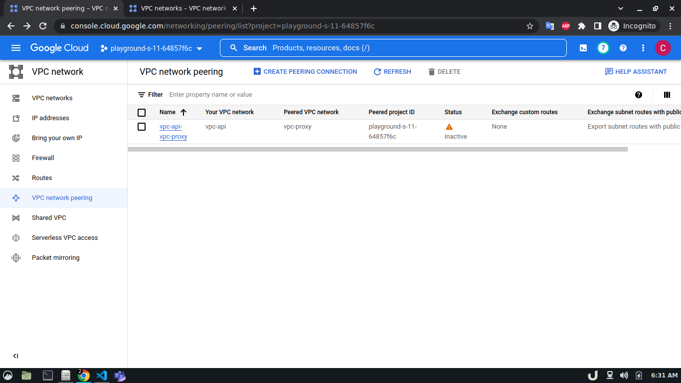
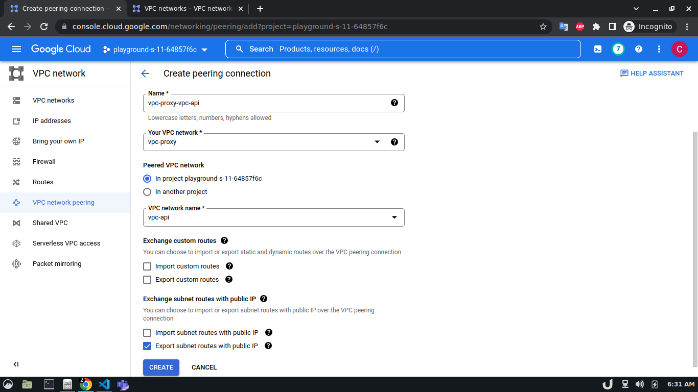
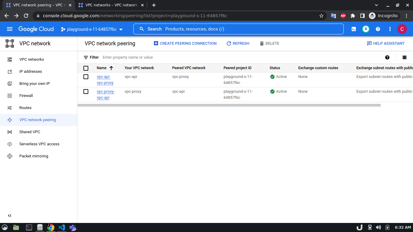
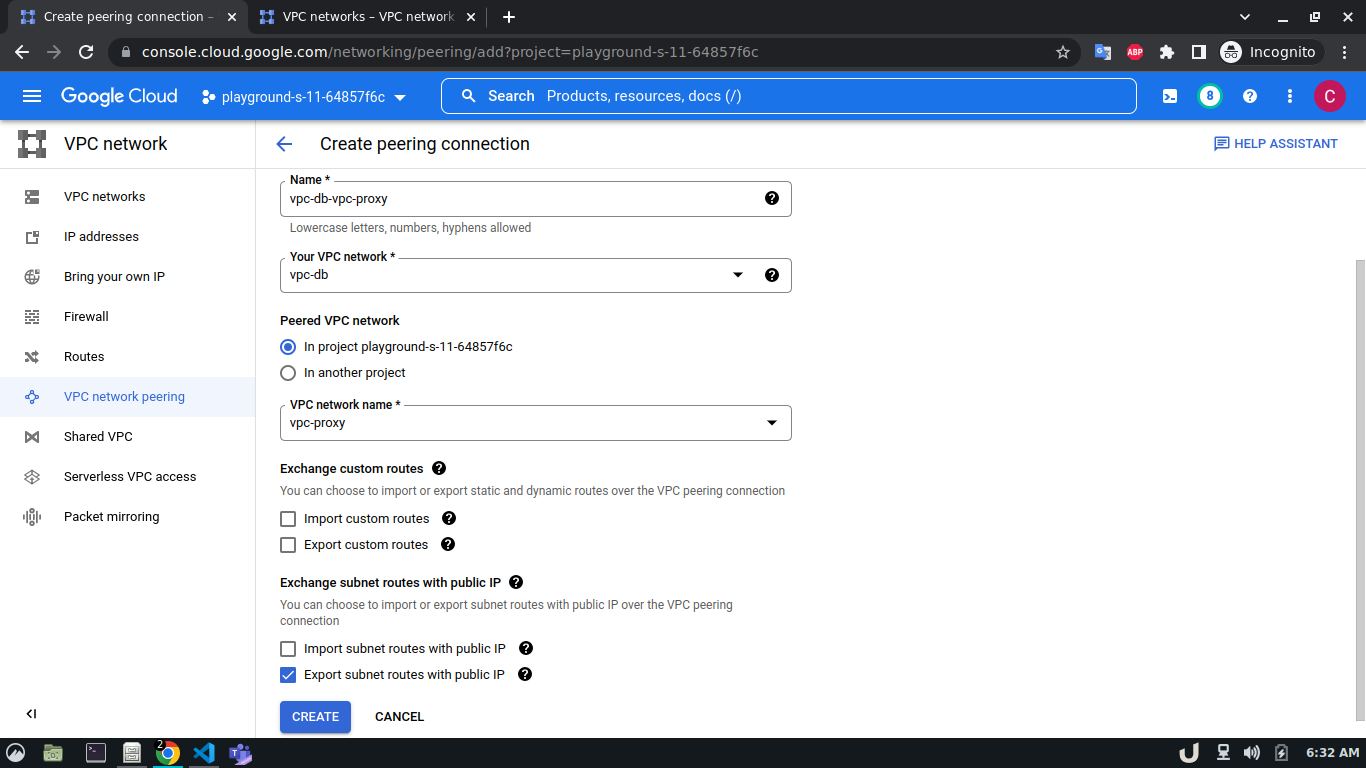
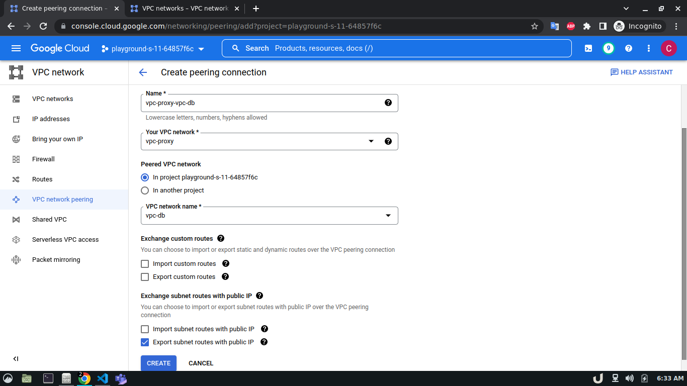
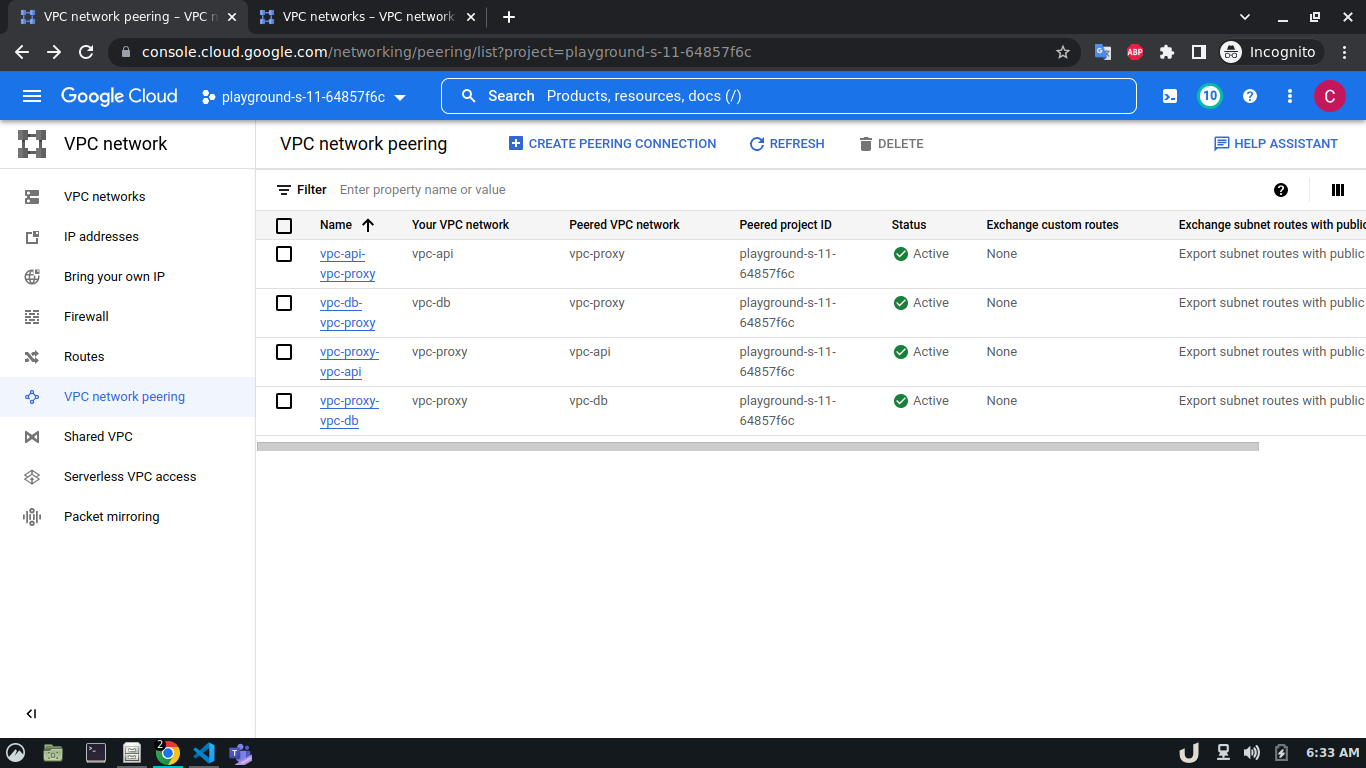
Now, we have three VM servers that are on three different VPCs. Therefore, these servers won't be able to communicate with each other. To establish a connection between two VPC's we need to develop a VPC peering connection. As this is a bidirectional connection, we need to establish the connection both ways e.g. for VPC A and VPC B, we'll create a peering network from VPC A to VPC B and then also, create another peering network from VPC B to VPC A. For the demo, we'll create a connection between vpc-api & vpc-proxy as well as vpc-proxy & vpc-db. We'll not create a connection between vpc-api & vpc-db as the API service will not directly communicate with the DB rather use the proxy server to establish that communication.
The step-by-step process for creating a peering connection is shown below,
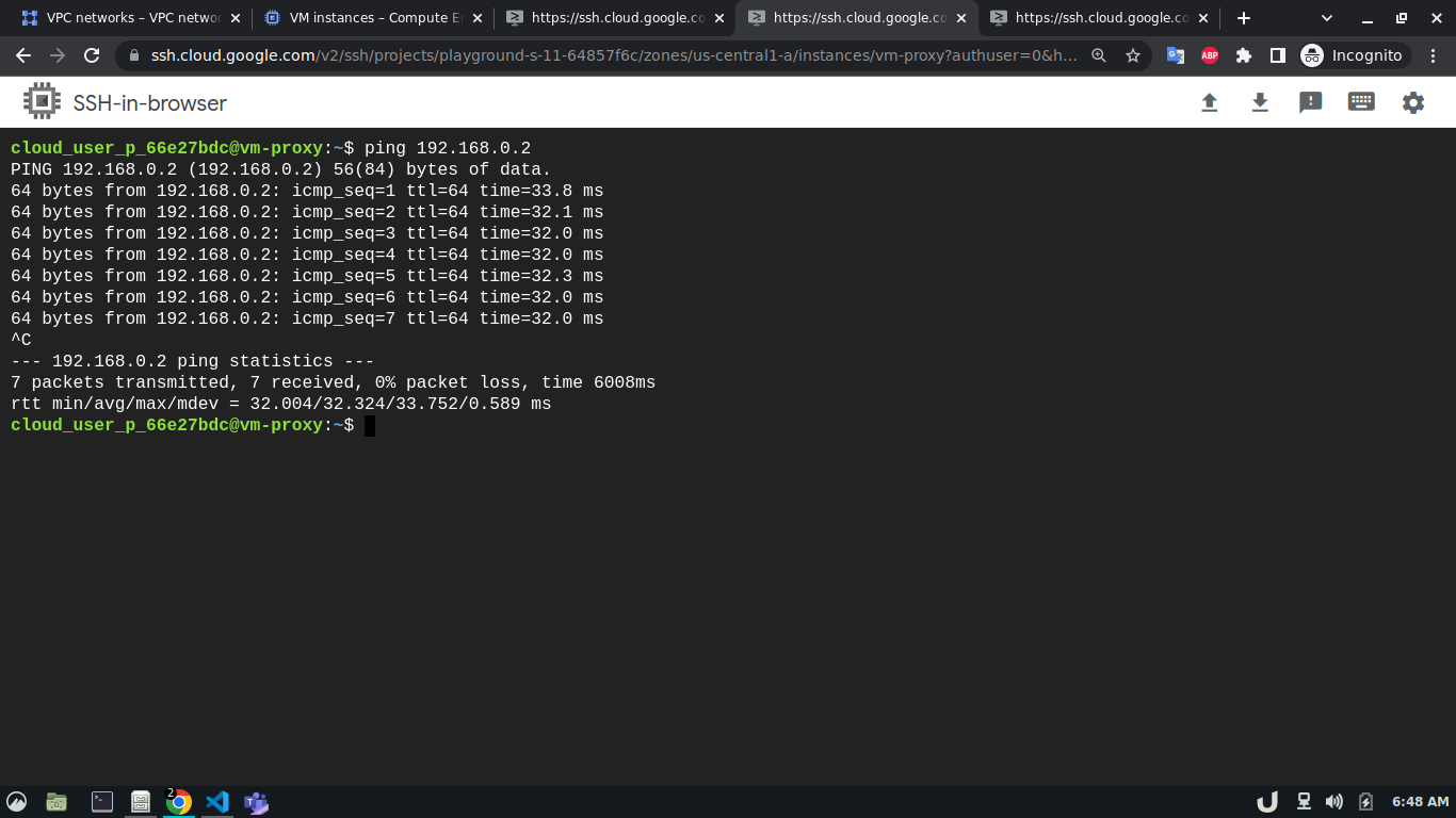
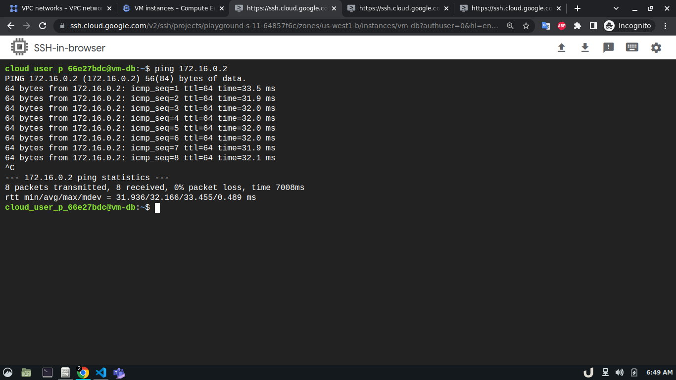
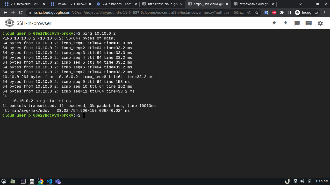
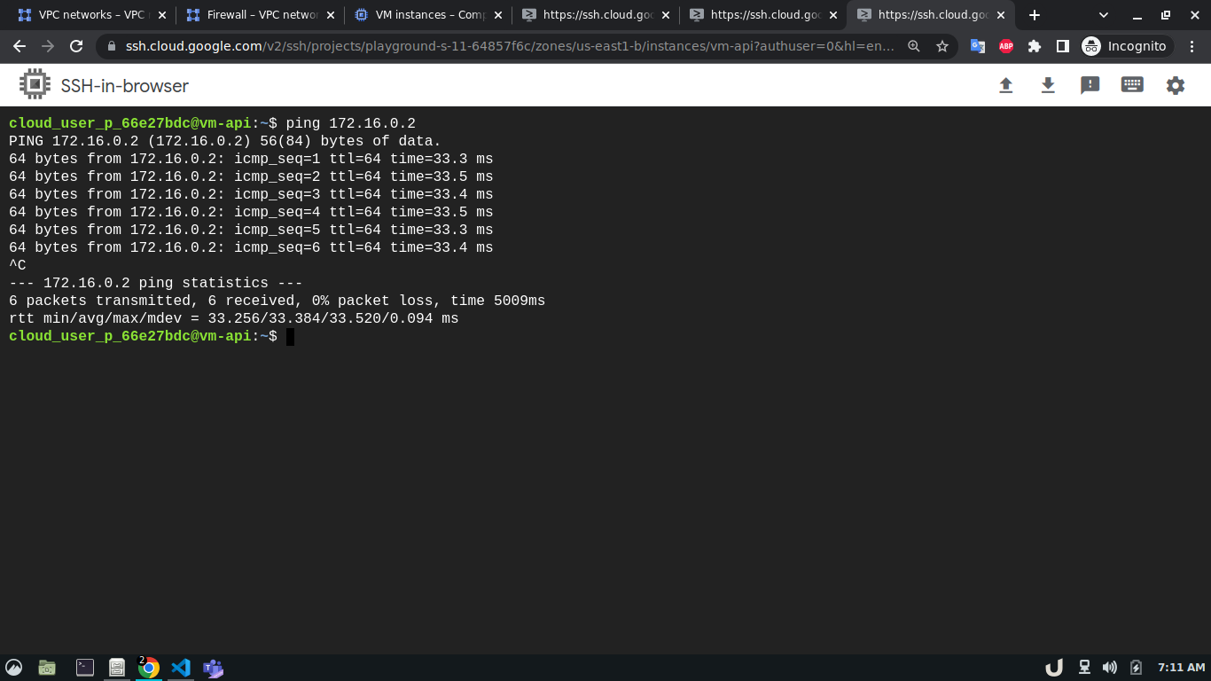
Now, we can test the connection between the VPC using ping command which sends an ICMP ECHO_REQUEST to network hosts. To test the connection we'll require the IP address of the servers within each VPC. We can see obtain that by going to the VM Instances panel in the Compute Engine option from the menu. Once we obtain the IP address, we can ssh into each server and use ping to test the connection with another server that is in the peered network of that VPC. Here, first, we'll ssh into the vm-proxy, and type ping <IP_OF_DESTINATION_SERVER> in the command line to connect with the vm-db server. We'll repeat the process for vm-db to vm-proxy, vm-proxy to vm-api and vm-api to vm-proxy to test those connections. If a connection gets established, it will log statistics in the cli.
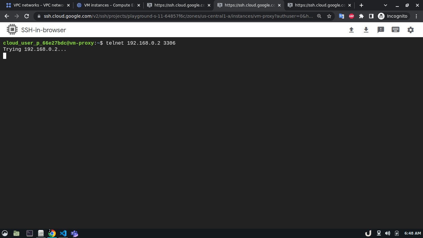
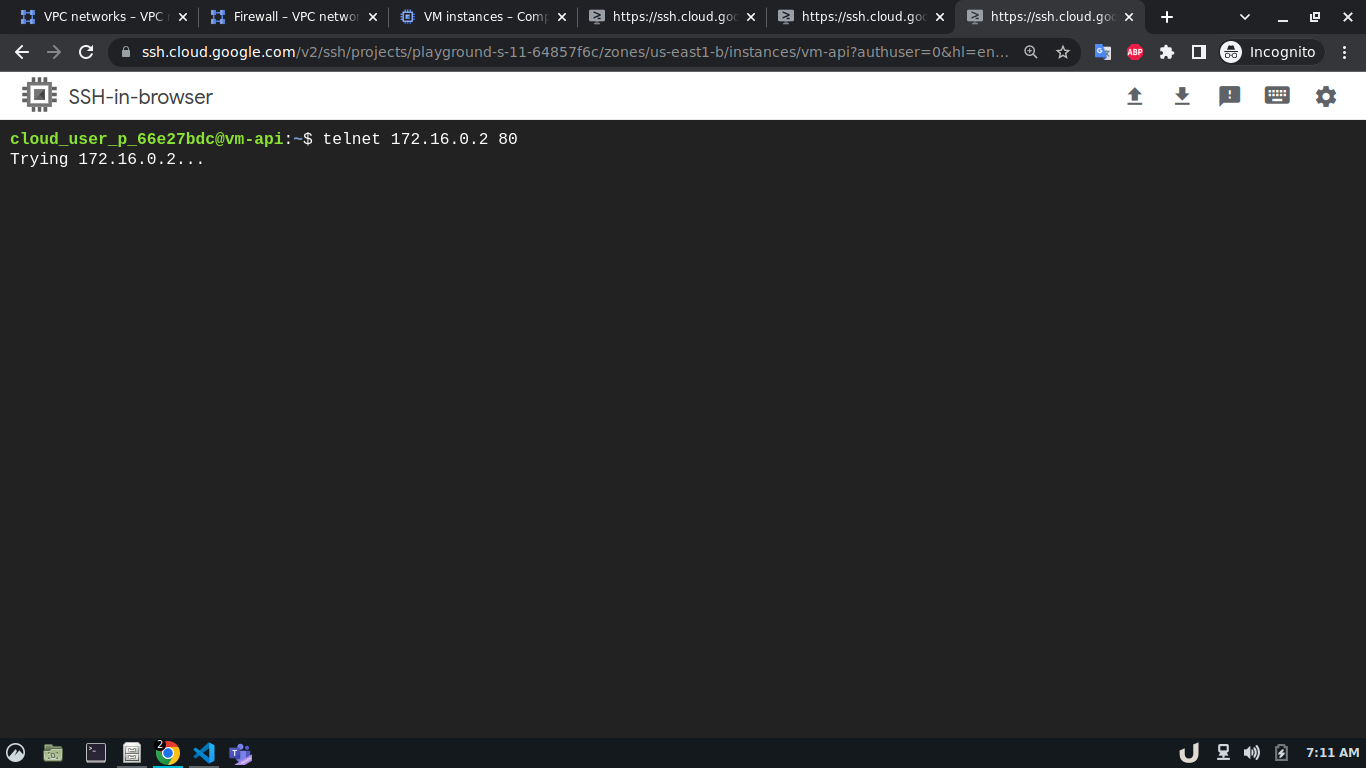
In our architecture (Fig 1.), the vm-proxy server will communicate with the vm-db server using port 3306. Similarly, the vm-api server will communicate with the vm-proxy server on port 80. We can use telnet to check if respective servers are listening to the intended port. We can do so by running telnet <DESTINATION_IP> <DESTINATION_PORT> on cli which will use TCP protocol to connect to the destination server. Now, using telnet will try to connect to DB from the proxy server, it will just keep on trying without ever establishing the connection.
The reason for the telnet's failure is the infamous Firewall!
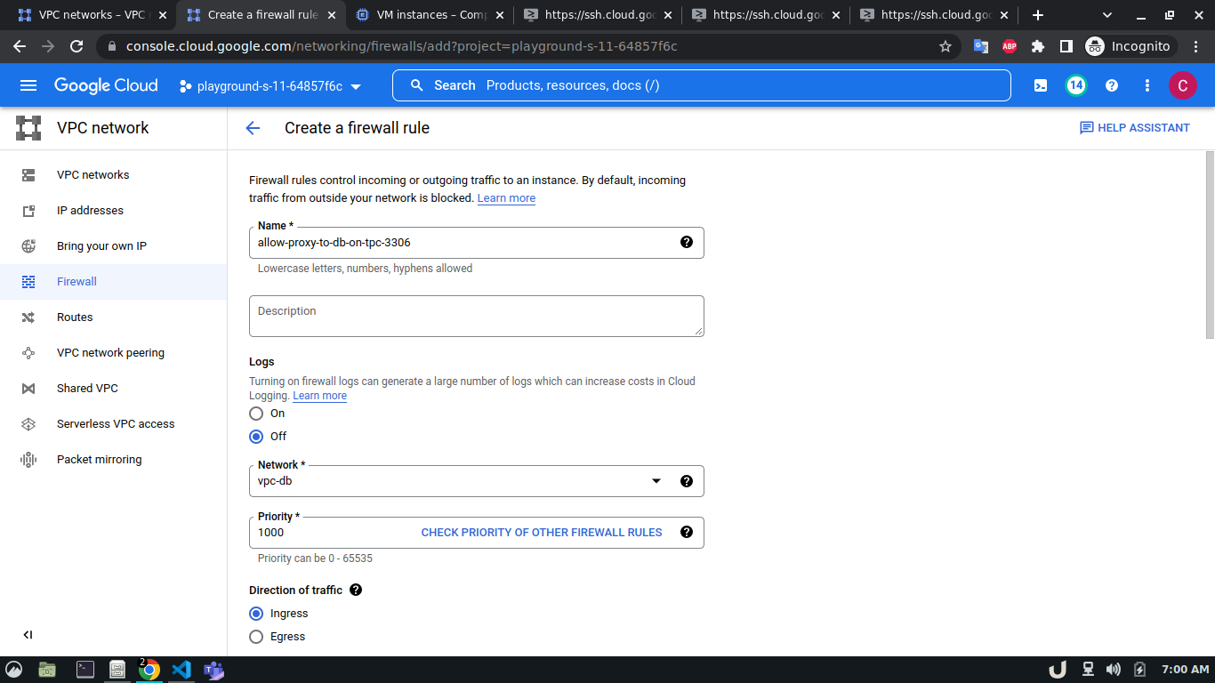
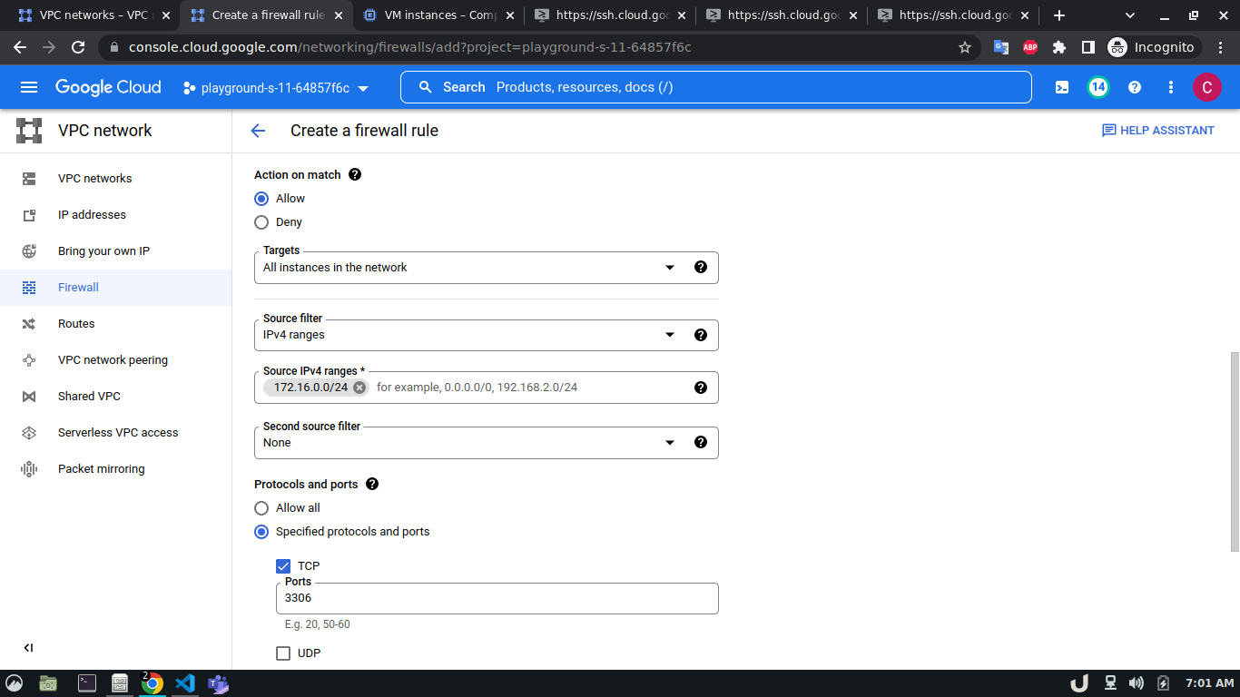
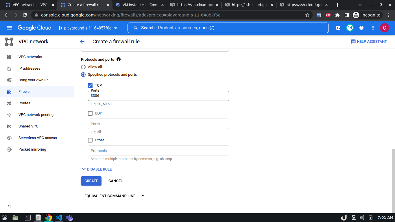
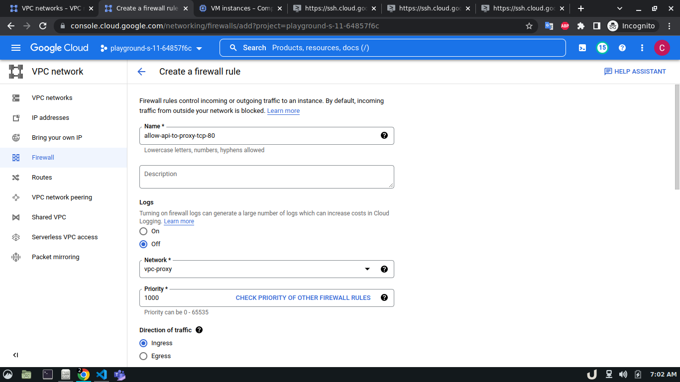
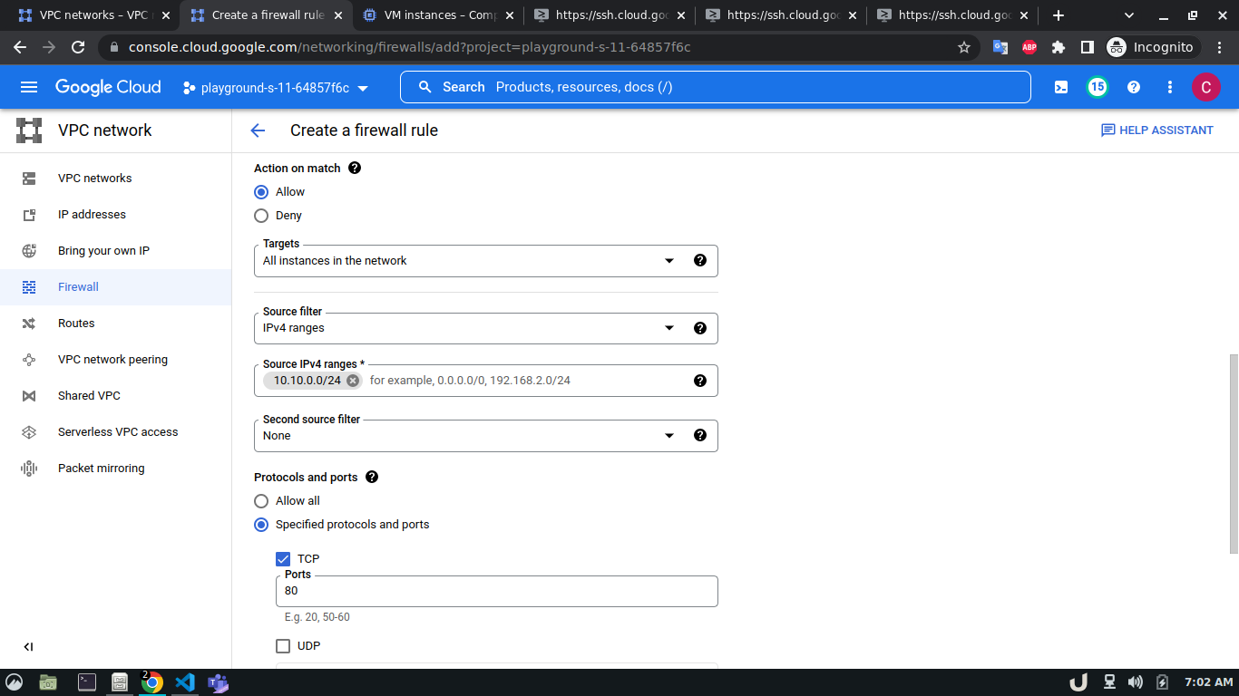
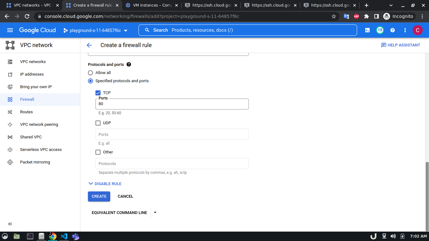
To allow TCP connection on a certain port to a VM inside a VPC, we need to allow the ingress to that port on the firewall. The enable the firewall, select the Firewall in the VPC network option in the menu. Click on CREATE FIREWALL RULE and provide a name. Now select the network. The network will be the VPC that you want to connect to. Select Targets as All instances in the network. Now, provide the source IPv4 range e.g. as the proxy server will try to connect to the DB server, this range will be the proxy server's IP or the network in which the server is hosted. Now, select the Specified protocols and ports radio button, check the TCP and type the desired port in the port field e.g. for DB server it will be 3306. Click on the create button to finish up the process.
The step-by-step process for creating a firewall rule is shown below,
Now, that we've allowed ingress for the DB server on port 3306 from the proxy server, and port 80 for the proxy server from the API server, running the telnet command mentioned previously will establish a successful connection.
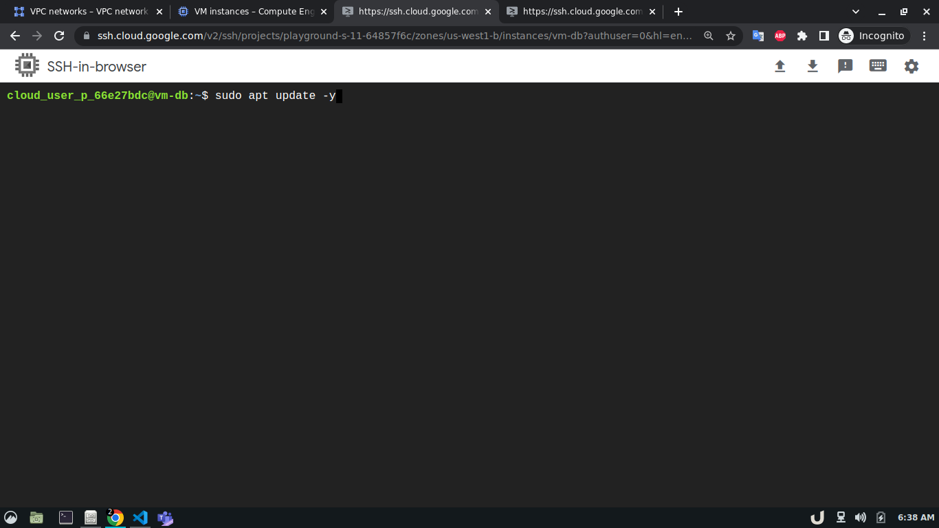
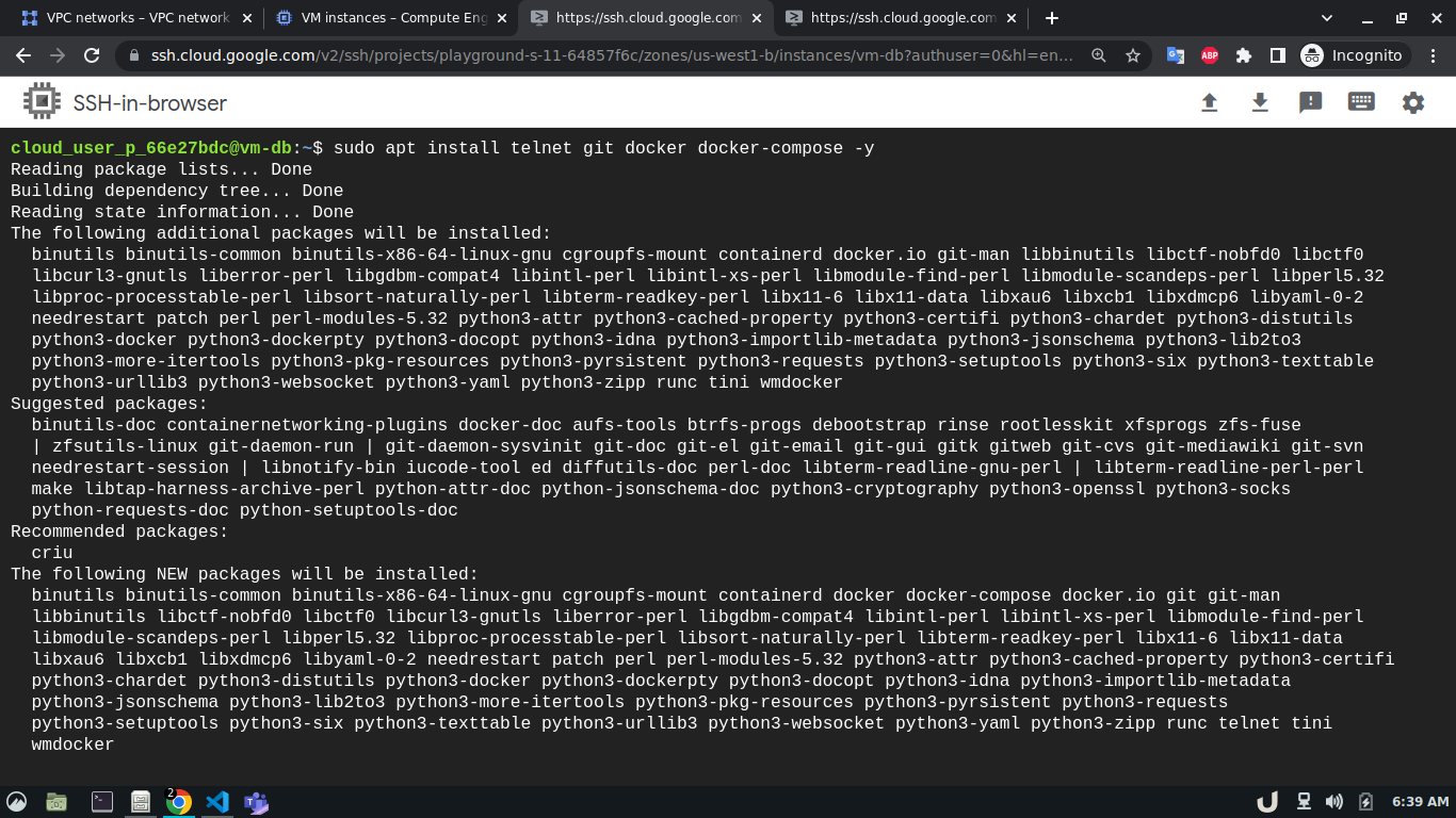
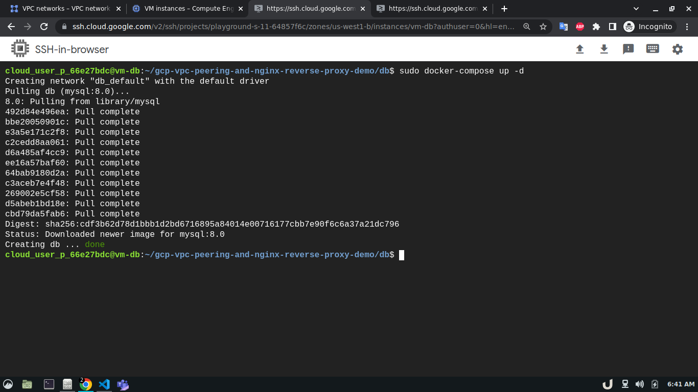
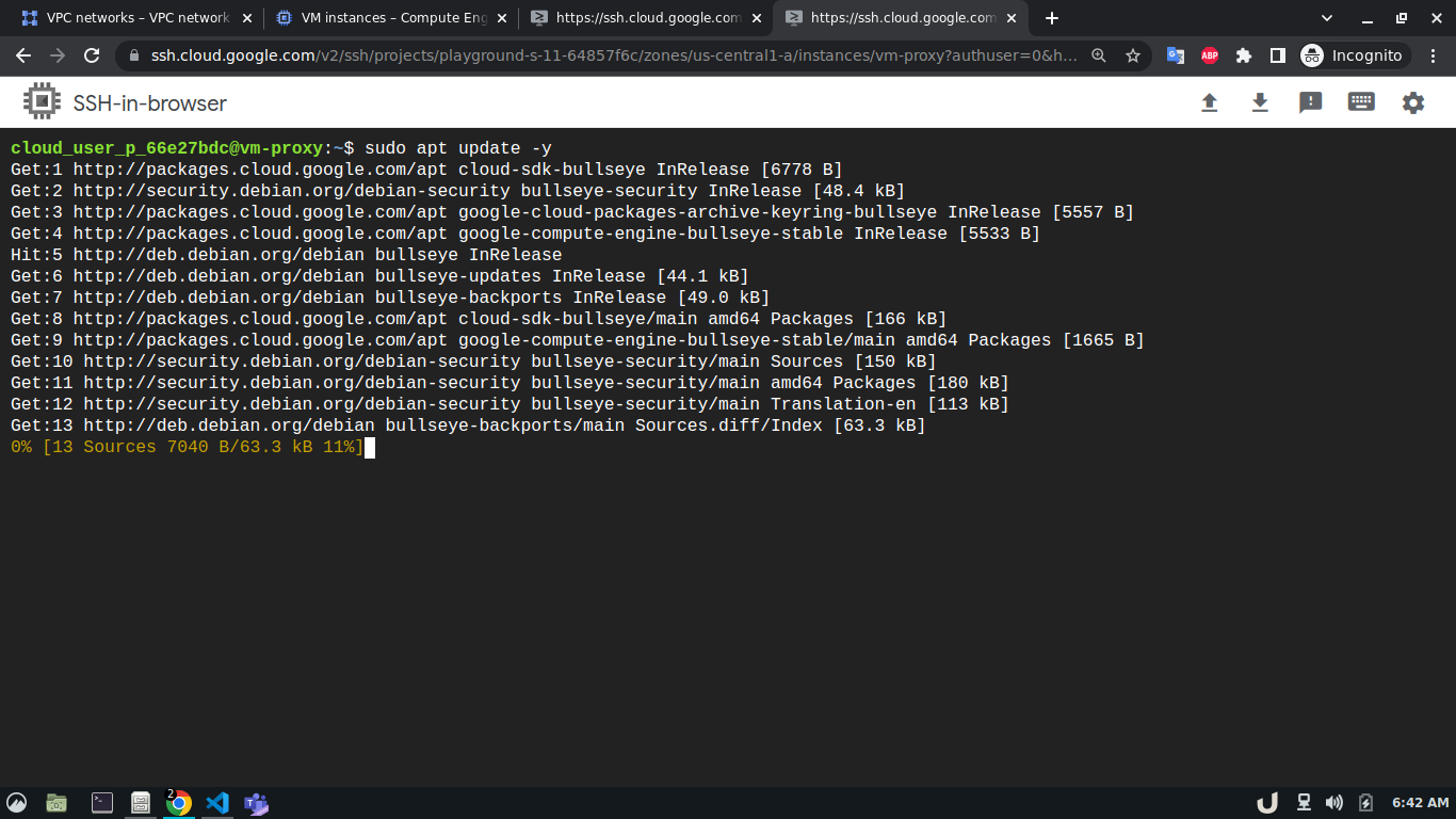
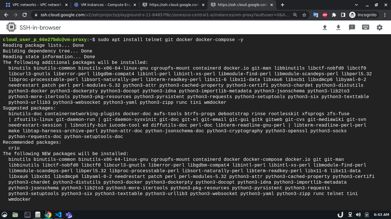
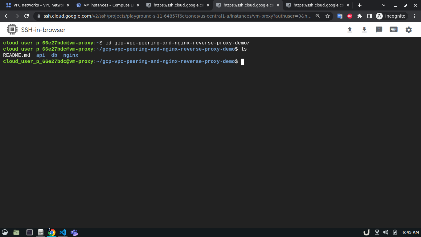
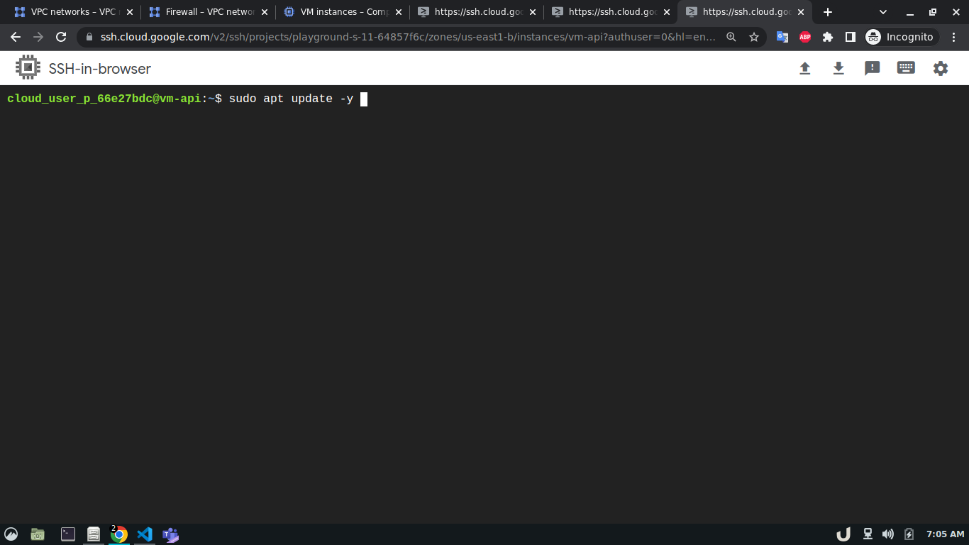
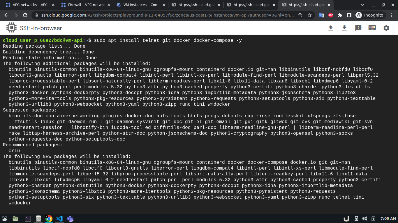
Now, we can ssh into each VM server and start creating the services they will be hosting. To ease the process, this repo contains all the necessary files for docker containers that will act as services inside each VM. After getting into the cli of each VM, we'll update the system and install git, telnet, docker and docker-compose using the following command,
sudo apt update -y
sudo apt install git telnet docker docker-compose -y
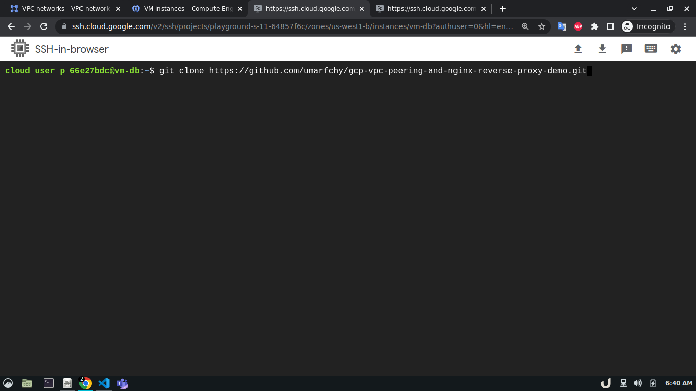
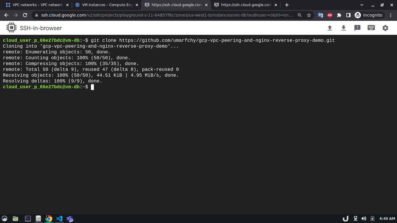
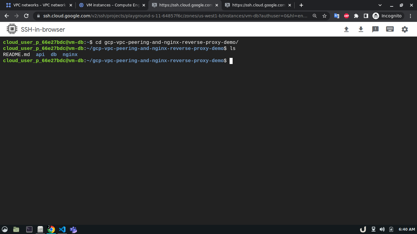
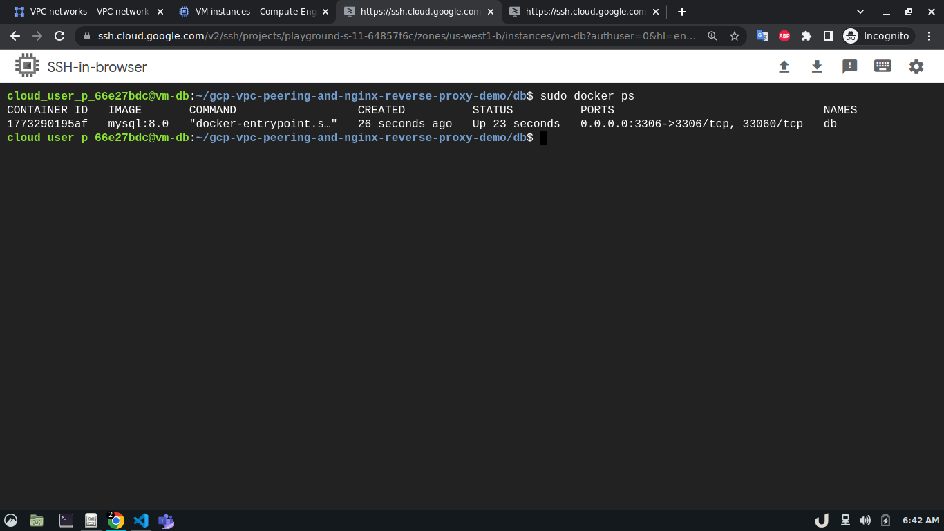
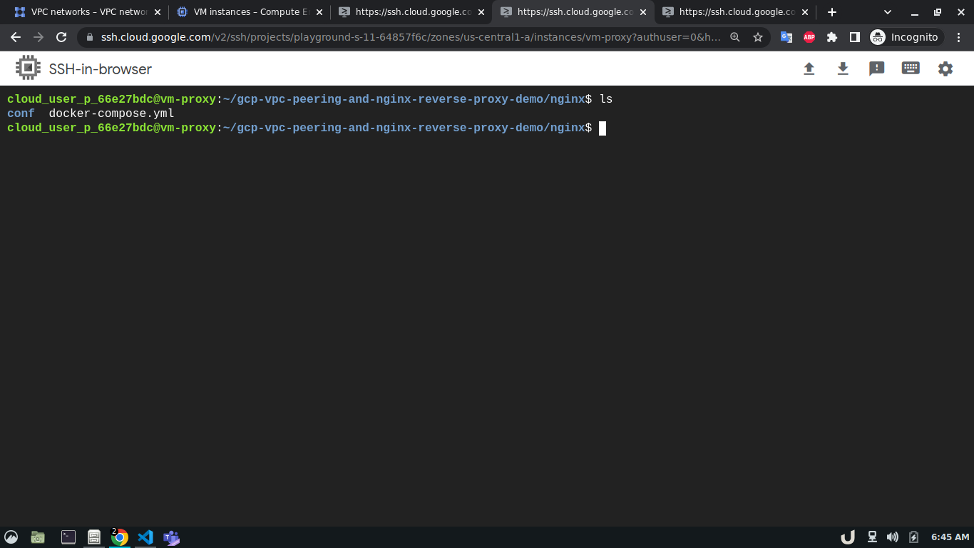
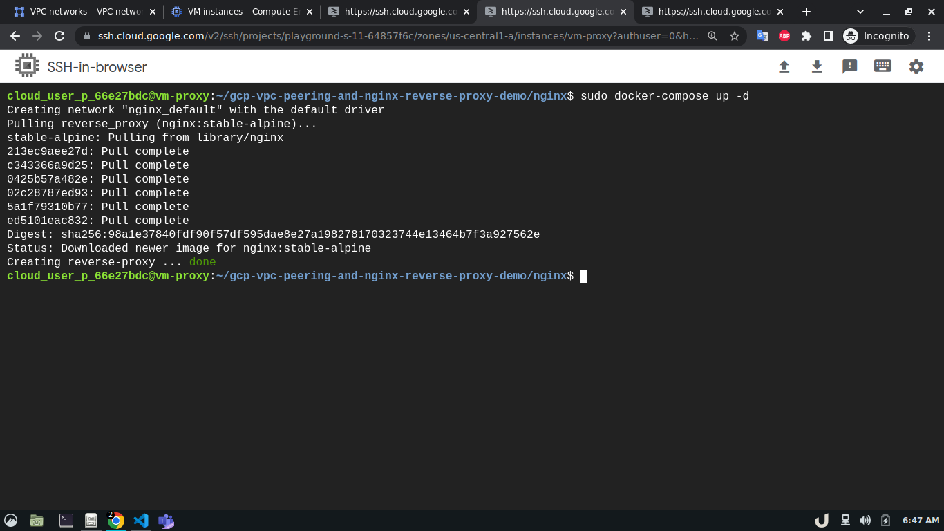
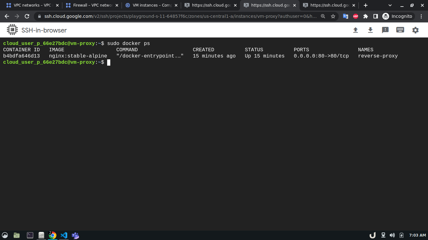
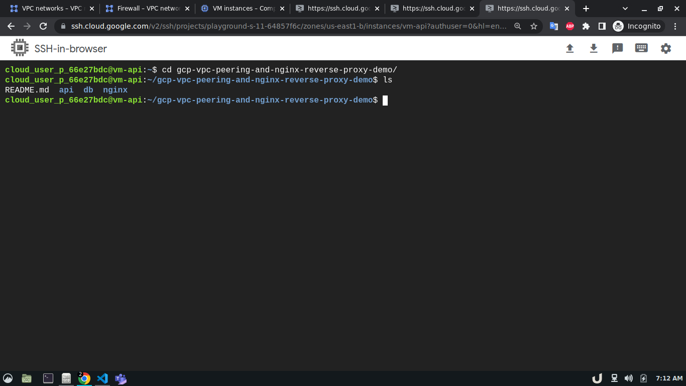
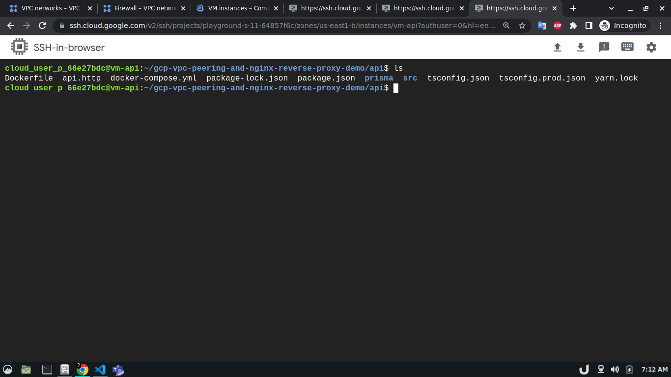
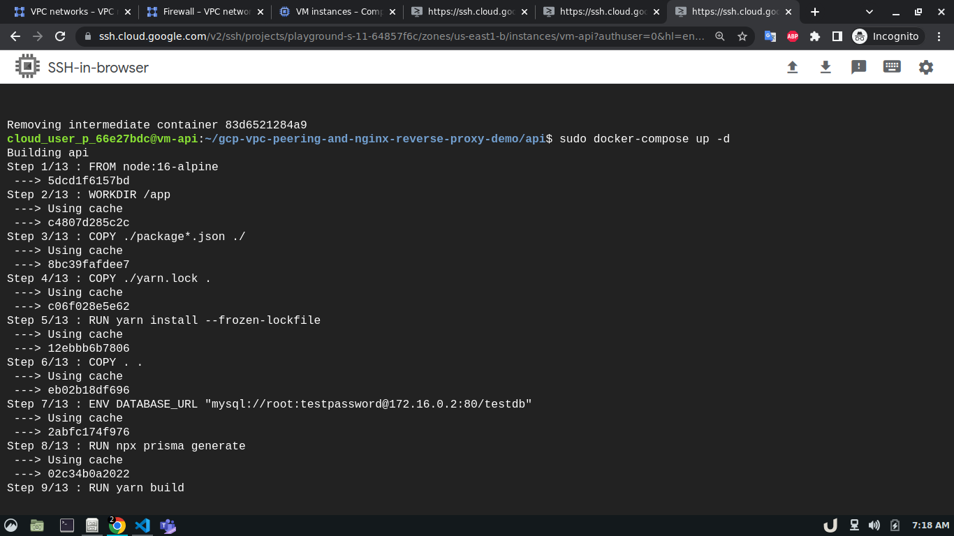
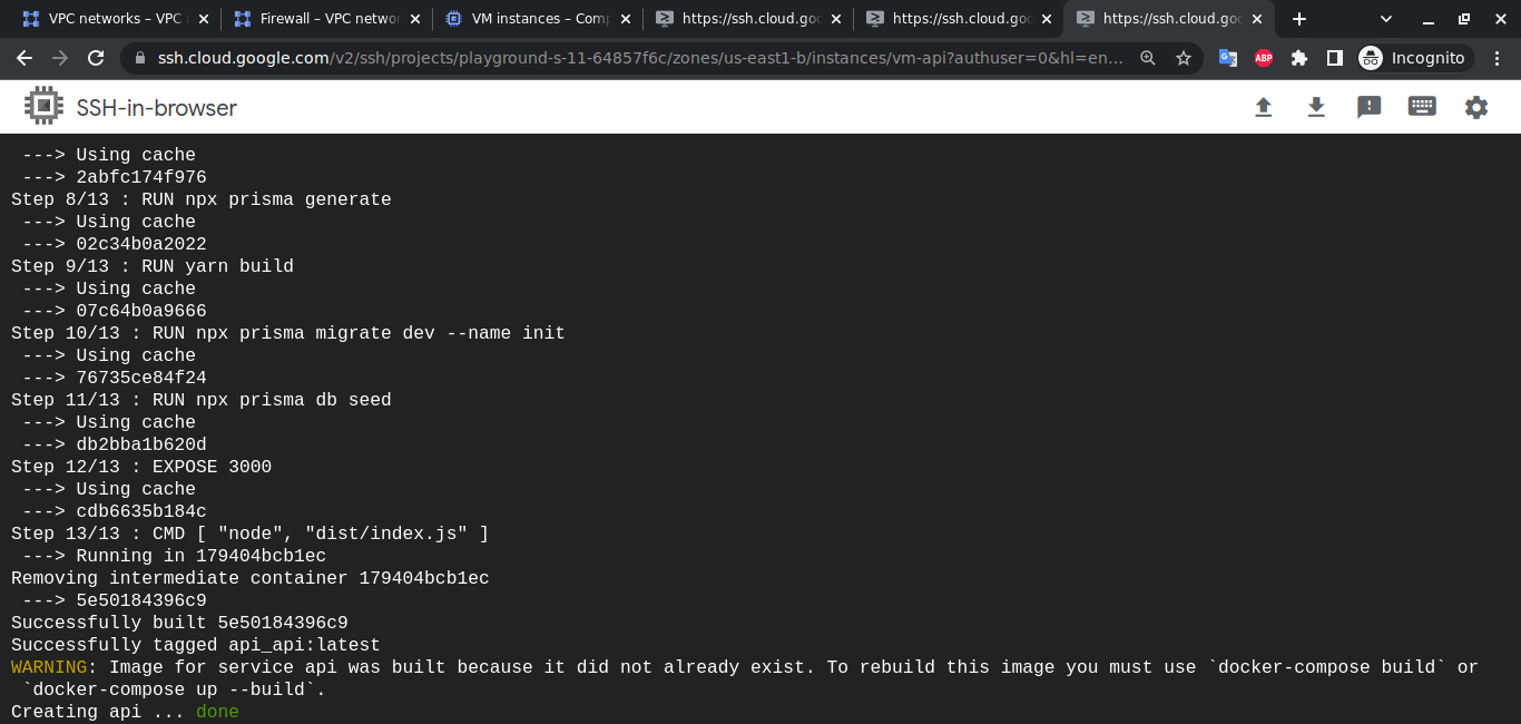
Afterward, we'll clone this repository to each VM. We'll move to the directory depending on the service and use sudo docker-compose up -d command to start the service. For example, to spin up the database service, we'll ssh into vm-db, clone the repository, move to db directory using cd <REPOSITORY_NAME>/db and run sudo docker-compose up to start the db container. We'll do similar for api and reverse-proxy container
Note The services need to be in the following order
dbfollowed byreverse-proxyfollowed byapi. This is cruicial as theapiassumes that thedbservice is already running and will try to populate some inital data when it is started the first time.
The step-by-step process for creating service containers is shown below,
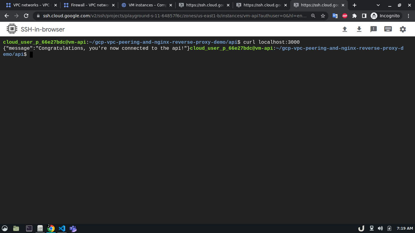
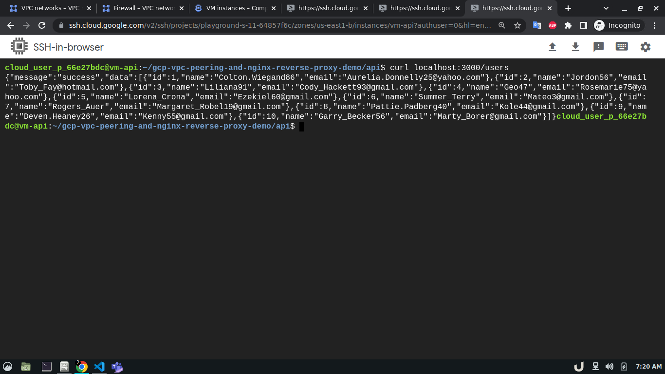
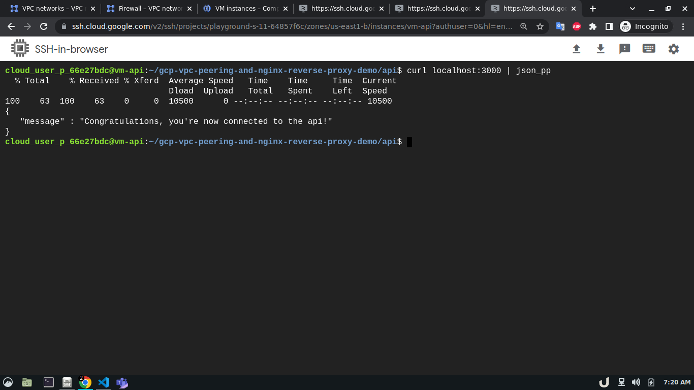
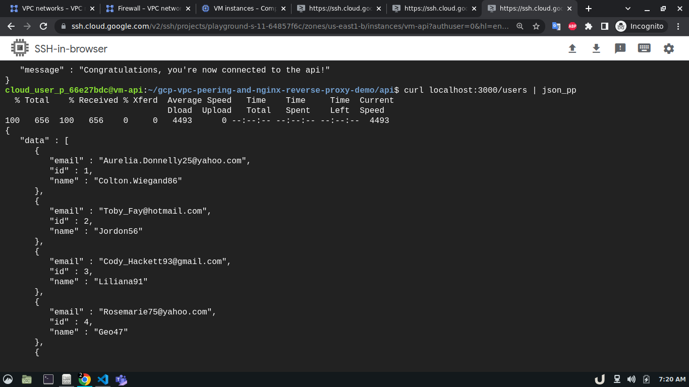
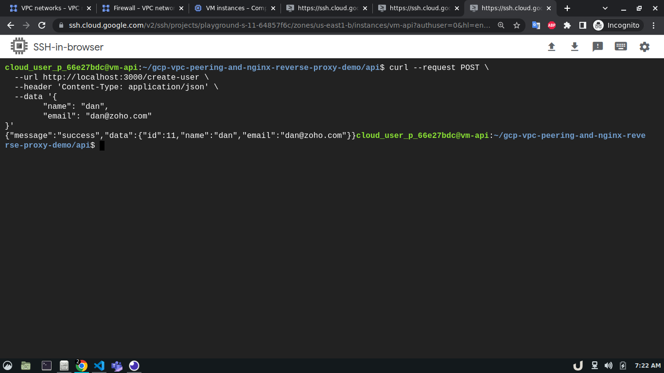
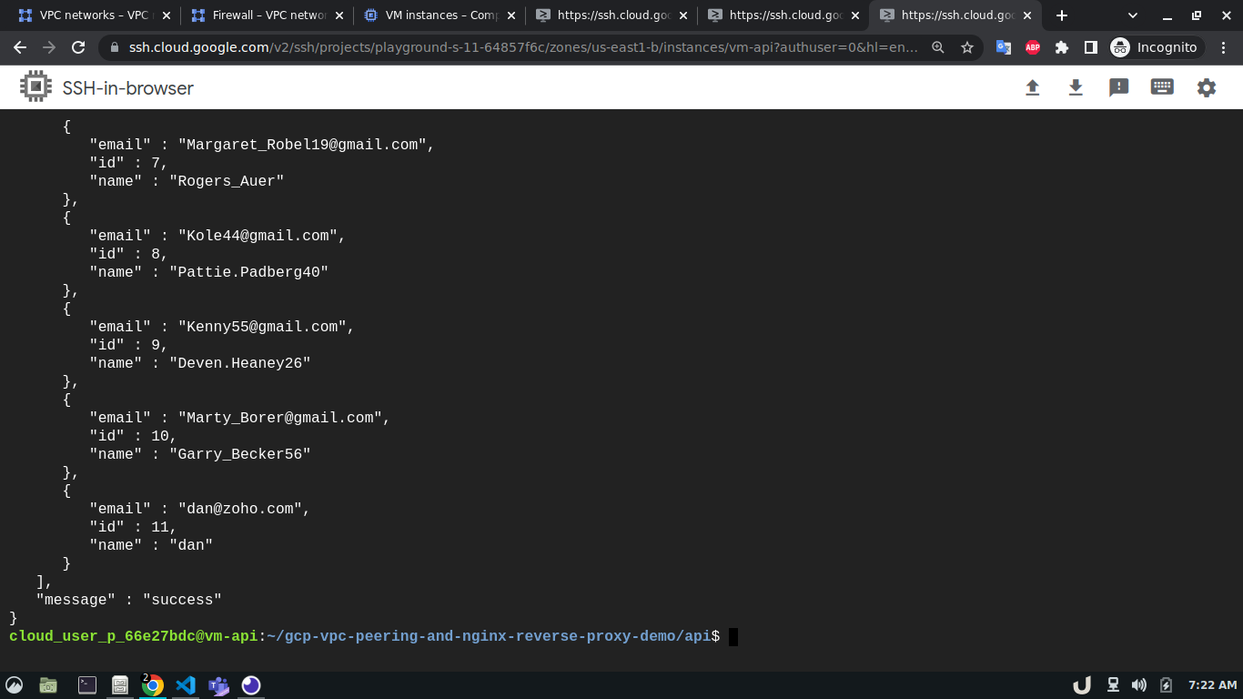
Once all the containers are up and running we can test the API using curl command from the cli of vm-api. Here, the api service is making requests to the proxy service for the data. As the proxy service gets the request it forwards the request to the db service which in turn responds depending on the query. This response from the db service then goes to the proxy service which in turn sends the response to the api service. You see the results below,
We can see a successful response from the server which suggests the overall communication was successful. This marks the end of this tutorial.
Thanks for reading.


