All the source codes used for this study are temporarily in this GitHub repository. They will be moved to this repository in the near future.
IFMHA includes 2,802,532 field measurements collected at 10,050 USGS gage sites across the US.
The time span of these measurements is from 05-05-1845 to 10-24-2022. IFMHA extends the HYDRoSWOT dataset with
the entire record of field measurements within NWIS including different types of field measurement methods
(see Table 1). The number of unique gage sites included in IFMHA is 10,050 which is 31 sites less than HYDRoSWOT
(17 of these stations are operated by an agency other than USGS, and the data for the other 14 stations are not
available on the USGS website). IFMHA augmented the NWIS field measurements by adding relevant attributes reported
in the NHDPlusV21 dataset.
Table 1. The different types of USGS streamflow field measurements methods.
| Method | Description | Frequency | Percent |
|---|---|---|---|
| UNSPE | Unspecified | 1204516 | 43.19% |
| QSCMM | Discharge, measured, midsection method | 792169 | 28.40% |
| QADCP | Discharge, measured, ADCP from moving boat | 437418 | 15.68% |
| OTHER | 347104 | 12.45% | |
| QFLUM | Discharge, measured, flume | 3888 | 0.14% |
| QIDIR | Discharge, measured, indirect method | 2959 | 0.11% |
| QVOLM | Discharge, measured, volumetric | 900 | 0.03% |
| NONE | 4 | 0.00% | |
| ACOUS | Acoustic Doppler Current Profile (ADCP) | 2 | 0.00% |
| ESTIM | Estimated | 1 | 0.00% |
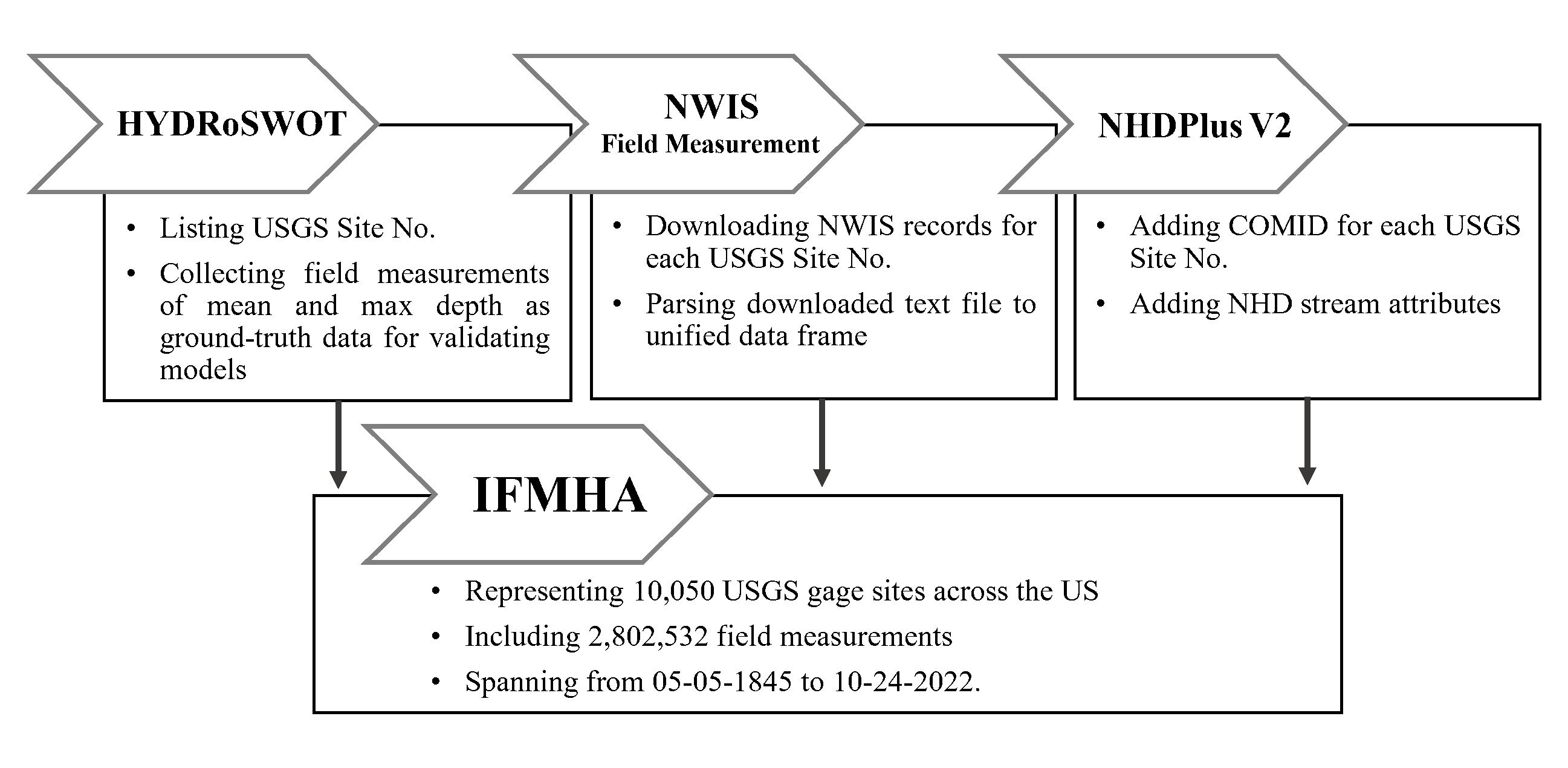
IFMHA consists of three main sources of data including HYDRoSWOT, NWIS field measurements, and NHDPlus V2 datasets. The order and process of incorporating each dataset for the compilation of IFMHA are depicted in Figure 1. The flowchart outlines the sequential steps involved in dataset adoption.
 Figure 1. Flowchart illustrates the incorporation of data sources for the compilation of IFMHA.
For the compilation of IFMHA, field measurements were queried in a tab-separated format from NWIS Site Inventory and then parsed and converted into a unified data frame comprised of records for all sites. For this purpose, URL links for each USGS site station were first created using the list of site numbers in the HYDRoSWOT dataset. Then, field measurements for each site station were queried from the NWIS Web Interface using the URL links. Finally, the requested text file of each site was parsed into a unified data frame.
HYDRoSWOT is an extensive collection of USGS cross-section surveys for supporting Surface Water Oceanographic Topography
(SWOT). The dataset comprises over 200,000 records of USGS Acoustic Doppler Current Profiler discharge measurements
collected from the USGS streamgaging network. It offers a range of essential fields, including mean and maximum depth,
velocity, discharge, stage, and water-surface width.
IFMHA borrows station_nm, dec_lat_va, dec_long_va, site_tp_cd, drain_area_va, contrib_drain_area_va
features from HYDRoSWOT.
National Hydrography Dataset Plus (NHDPlus) is a national geospatial surface water framework including the features
and capabilities of the National Hydrography Dataset (NHD), the National Elevation Dataset (NED), and the Watershed
Boundary Dataset (WBD). NHDPlus integrates the vector NHD stream network and WBD hydrologic unit boundaries with the
NED gridded land surface.
IFMHA includes COMID, STATE_CD, STATE, DASqMi, DASqKm, LatSite, LonSite as well as FTYPE,
StreamOrde, SLOPE which are borrowed from NHDPlus_GageLoc and NHDPlus_NHDFlowline_Network of
NHDPlusV2.
After removing zero and missing values of three important columns including discharge_va, gage_height_va, and
chan_width that represent streamflow, river stage and channel width, respectively, 2,312,896 records remain.
Moreover, to conduct significant statistics, sites with more than 50 observations are selected from valid records
(out of no zero/missing records). Eventually, 2,279,530 observations (represented by 7,446 sites) are
considered for following analyses.
2,199,163 observations (represented by 7,098 sites) include only positive values for discharge. The river stage verses discharge plot for some sample sites are as follows:
 Figure 2. Site locations including only positive values for discharge.
80,367 observations (represented by 348 sites) include both negative and positive values for discharge. The river stage verses discharge plot for some sample sites are as follows:
 Figure 3. Site locations including both negative and positive values for discharge.
Among sites having negative discharge in their records, there are still some cases that the relation between stage and discharge is more like sites with positive discharge.
 Figure 4. Site with negative/positive discharge that follow the behavior of sites with only positive discharge.
These sites are generally located near the costal area or control points. We will omit these site locations from all following analyses.
 Figure 5. Location of sites that includes both negative and positive values for discharge.
The role of channel (bankfull) geometry representation in hydrological modeling is important. Bankfull discharge, for instance, is considered to be the most effective flow for moving sediment, forming or removing bars, forming or changing bends and meanders, and generally doing work that results in the average morphological characteristics of channels (Dunne and Leopold, 1978). According to the definition, "In the case of rivers with floodplains, river stage tends to increase rapidly with increasing water discharge when all the flow is confined to the channel, but much less rapidly when the flow spills significantly onto the floodplain. The rollover (i.e., sudden change of slope) in the curve defines bankfull discharge" Gary Parker, Morphodynamics e-book. However, as it is shown in the Figure 2, finding those observations that represent bankfull characteristics is not always an easy task.
Here, instead of selecting one observation to represent the channel in a specific state (e.g., bankfull), the best fitted distribution to the important properties of the channel (discharge, stage and width) are calculated. Thus, each site station is represented by the best fitted distribution parameters associated with channel geometry of that site. Let’s assume normal distribution is the best fit for the whole observations of discharge in a hypothetical site station. So, two values (i.e., mean and std) can represent all of those observations for discharge. Through this way, all observations of a site can be summarized in one record.
The histogram of discharge observations for 16 site stations which were randomly selected is shown in the Figure 6.
 Figure 6. The histogram of channel discharge observations for different site stations.
Ten most common distributions
(i.e., cauchy, chi2, expon, exponpow, gamma, lognorm, norm, powerlaw, rayleigh, uniform)
were fitted to discharge observations of 7,098 sites (including only positive values for discharge). The frequency
of best fitted distribution is shown in the Figure 7. This figure shows lognorm is the best fit for more than 50%
of the site stations.
 Figure 7. The frequency of best fitted distribution for channel discharge.
The same statistical analysis was done for channel width. The histogram of channel width observations for 16 different site stations is shown in Figure 8. In comparison with channel discharge, channel width distribution of different site stations does not follow same pattern. In some cases (indicated by red squares), channel width distributions have more than one peak.
 Figure 8. The histogram of channel width observations for different site stations.
The frequency of best fitted distribution for channel width is shown in the Figure 9. This figure shows cauchy is
the best fit for about 4,000 site stations.
 Figure 9. The frequency of best fitted distribution for channel width.
Firs it should be mentioned that this type of distribution indicates that there are more than one group in the data. Thus, each distribution group can represent a specific hydrologic phenomenon:
- Changing characteristics of streamflow over time (seasonality or chronologically).
- Active-channel, bankfull and overbank flow stages.
- Changing geometry over time (naturally or artificially).
- Changing measurement locations in the field.
- Measuring channel geometry and characteristics of streamflow for tributaries, instead of the main channel.
The site stations having multi-modal distributions are discussed in the following parts:
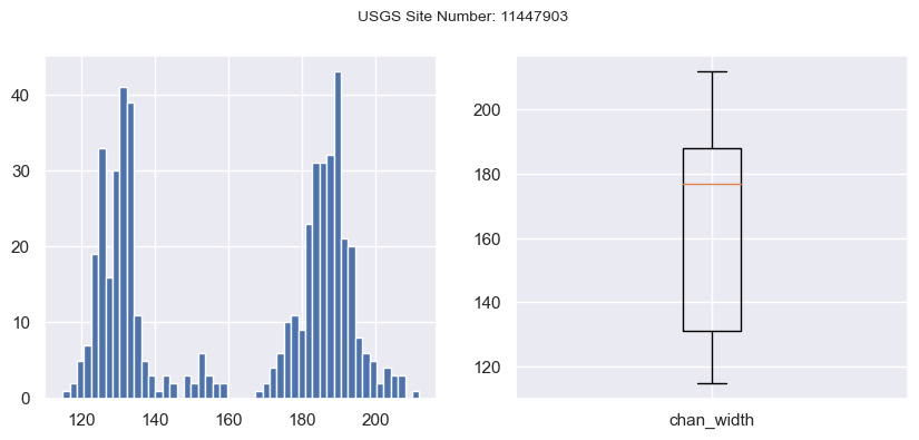
Figure 10 approves two peaks in channel width distribution for the case of USGS site number 11447903.
Figure 10. Bi-modal distribution of Channel width.Variation of measured width for the existing field observations can be a result of changing location of measurement.
TAURAAT includes a feature column, chan_name, indicating the locations where the measurements were done. In the case
of site 11447903, there are several names such as Imported Channel 1, Georgiana Slough Nr..., GSS001-009.
Considering the similarities of the channel names, they were categorized in three groups and the variation of channel
width for each group is shown in Figure 11. It seems channel 2 and channel 3 can be summarized in one group,
as the values of channel width are in the same range for both group. However, the range of values for the first channel
implies existing tributary or two different locations for doing filed measurements.
Figure 11. The variation of channel width as a result of changing measurement locations.
In order to evaluate the channel width variation over time, width values were plotted according to the date of the measurement (Figure 12). This figure indicates the channel geometry might be changed over time.
Figure 12. The variation of channel width over time.
In order to systematically differentiate between two different groups of channel width, three different clustering
methods including KMeans, DBSCAN, and AgglomerativeClustering were implemented on the measured width. The result
of K-Means is shown in Figure 12.
Figure 12. The results of KMeans clustering (number of cluster=2).
Figure 13 shows histogram, Experimental Cumulative Distribution Function (ECDF), and box plot for channel width of USGS site number 05425500. ECDF is used to show there is no "Binning Bias," a pitfall of histogram, where you will get different representations of the same data as you change the number of bins to plot.
Figure 13. Bi-modal distribution and experimental CDF for Channel width.
The variation of channel width over time and the results of DBSCAN on the width values are shown in Figure 14. Width
measurements are generally dominated around two different values over time. This shows measurements might be done in
two different locations over time, or in two different streamflow stages (e.g., active-channel, bankfull, overbank).
DBSCAN model is instantiated with DBSCAN(eps=5, min_samples=20) and the results are as follows:
Figure 14. The results of DBSCAN clustering (number of cluster=2, green dots are considered as noisy samples).


