By Geeks Team CCSED 26 Level 1 Final Project
The line follower robot is a robot designed to trace a line on the ground with no physical connection. Our line follower uses a sensor to read the IR rays reflected from the ground to differentiate between the line and other parts on the ground.
The IR sensor reads are recieved by Arduino Uno as a microcontroller to control the robot motion and display its state on an LCD screen.
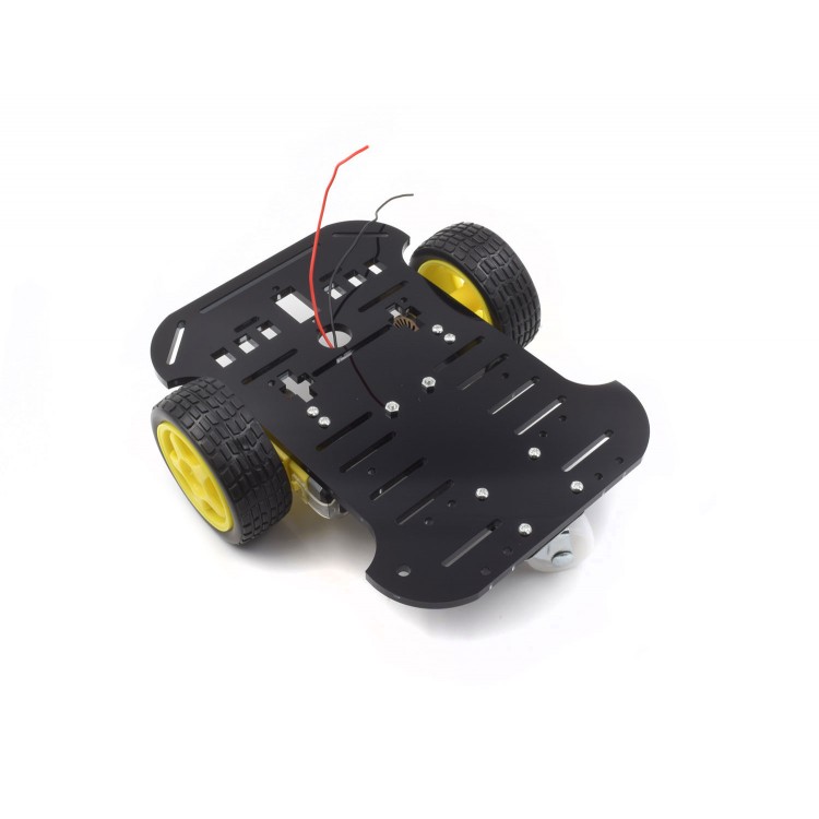
- Robot Car Acrylic Chassis (2WD)
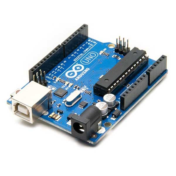
- Arduino Uno
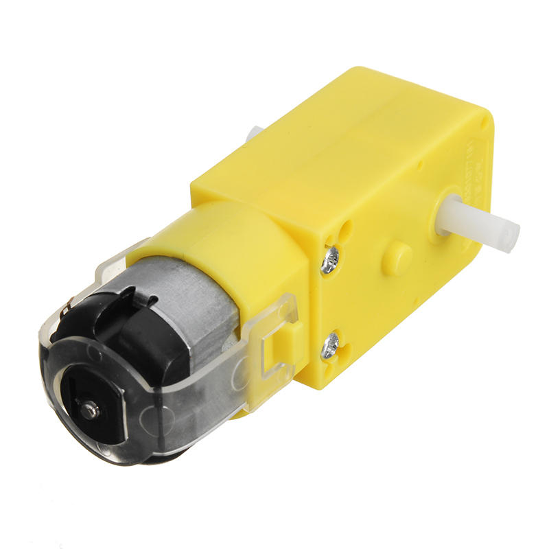
- DC Geared TT Motors (2x)
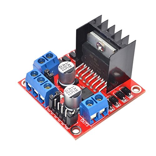
- Motor Driver (Model L298N)
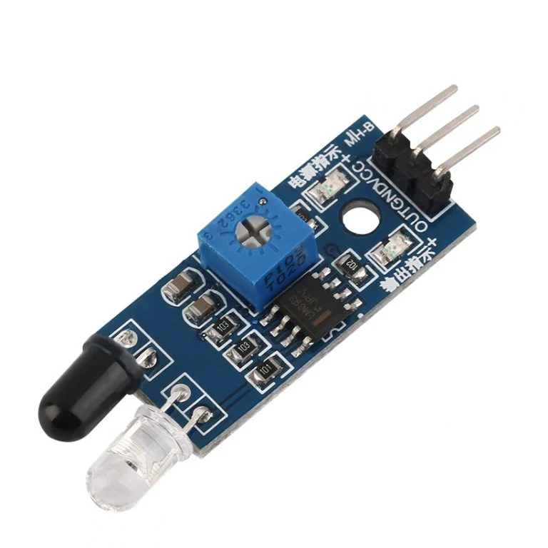
- IR Sensor Modules (3x)
- LCD 16x2 Model
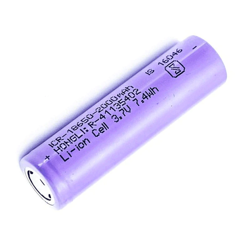
- 18650 Li-on Batteries 3.7V (3x)
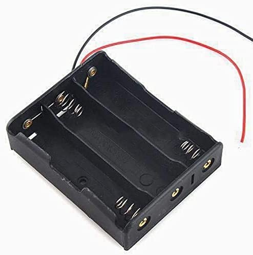
- 18650 3-Cell Battery Holder
- DC Switch
- Jumper Wires
- Fix all the components on the car chassis using connectors, screws and wax gun
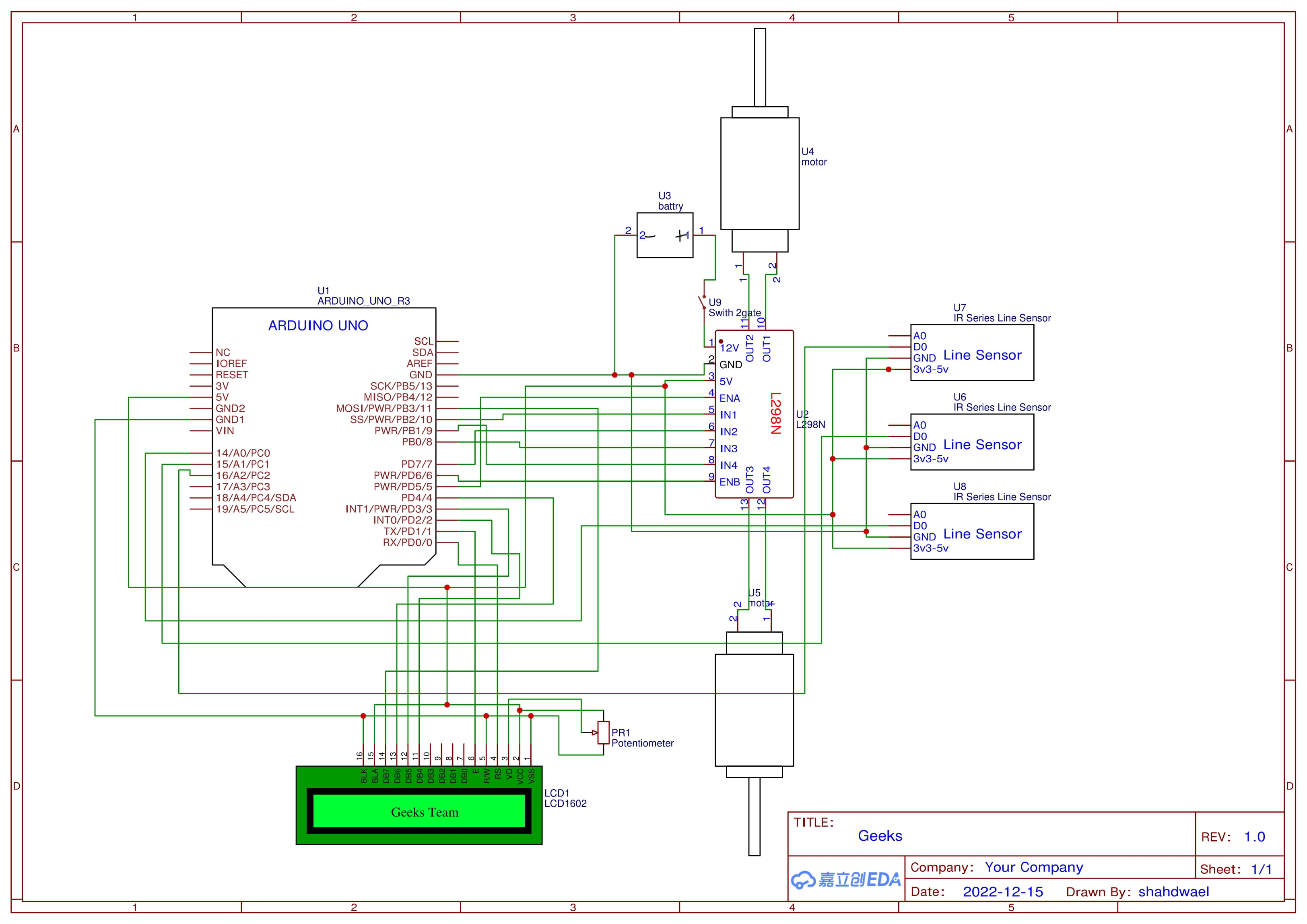
- Connect components together using jumper wires As shown in Connections section
- Implement the code and upload it through
Arduino IDEAs shown in Code section
- DC motors are connected to the Motor Driver and controlled by Arduino
- Reversing the polarity across the DC motor reverses its direction of motion
- Arduino Uno acts as a microcontroller that controls 14 digital i/o pins and 6 analog pins.
- All Components, including Arduino, take their voltage in a parallel connection through the Motor Driver
- The Motor Driver is directly connected to the battery with the switch in the middle
To view full diagram click here
| Motor Driver | Arduino Uno |
|---|---|
| ENA | D5 |
| IN1 | D10 |
| IN2 | D7 |
| IN3 | D8 |
| IN4 | D9 |
| ENB | D6 |
| LCD | Arduino Uno |
|---|---|
| RS | D0 |
| EN | D1 |
| D4 | D2 |
| D5 | D3 |
| D6 | D4 |
| D7 | D11 |
| Sensor | Arduino Uno |
|---|---|
| Right | A0 |
| Middle | A1 |
| Left | A2 |
- The code uses Object Oriented Programming models to represent each component as a class, and implement methods and properties connected to it inside these classes.
- The LCD is defined using
LiquidCrystallibrary, andScreenclass has methods to display team name, direction, timer and current area. - The class
Motorhas methods related to the motion of a single motor. - The class
Controlleris used to control the car motion through executing methods inside the two motor objects. - The class
Sensorhas a method to get the reading of the sensor. - We create an instance of each class at the begining of the program.
- Each class has an
initfunction which is executed in the programsetup. - Inside
loop, we get the reading of the 3 sensors and compare them to decide the current car motion usingif ... else if ... else ...and the execution of functions inside theControllerclass.
- Ahmed Abdelmonem Goda
- Ahmed Hossam Othman
- Fatma Soliman
- Seif El-Din Wael Sweilam
- Shahd Wael
- Sherif Mohamed Shaaban
- Shorouk Saad Abdelmonem
- Sohila Mostafa
