CXADC clock generator and audio ADC
A project to synchronously clock two (or more) CXADC PCIe cards and an extra audio ADC from an external clock generator, for VHS-Decode setups. This enables sync capturing of the two RF streams (RF Video and RF HiFi audio from a VHS), in addition to a stereo audio stream (linear VHS audio).
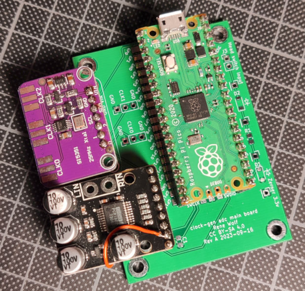
The above picture shows the mainboard, which you would typically mount inside your capture PC, along side the 2 CXADC cards. The below diagram shows how a typical VHS capture is setup using the clock generator + audio ADC (this project).
The project consists of 3 main components:
- A PCB adapter that is installed per PCIe card. It contains only a couple of passive components per cx25800-11z data sheet.
- The main PCB that combines a Raspberry Pi Pico, with an Adafruit Si5351A Clock Generator Breakout Board, and a PCM1802 board.
- The firmware for the Raspberry Pi Pico, that implements a USB sound card and also controls the Si5351A clock generator. The firmware is available pre-build and can be flashed to the Raspberry Pi Pico without additional tools.
To capture VHS conveniently and then decode it with the amazing VHS-Decode, you need two CXADC PCIe cards and an additional audio ADC. One CXADC card will capture the RF video stream at usually 20MSPS 10bit. The other CXADC card will capture RF HiFi audio at usually 10MSPS 8bit. The additional audio ADC captures the linear audio track from the VHS. So you have 3 independent pieces of hardware that each captures a part of the VHS tapes content.
Each of the 3 pieces has its own quartz oscillator, to drive its logic. CXADC PCIe cards usually come with a 28.6MHz quartz, that is commonly replaced with a 40MHz one for better performance. The additional linear audio stream could be captured with an additional USB audio interface, which of course has its own quartz.
As every real device, quartzes have tolerances, resulting in frequency errors. E.g. a 40MHz quartz might actually be 40.000005MHz or 39.999995MHz. This error is due to manufacturing tolerance and basically random. So each of the 3 quartzes will be slightly different, and you can't really know by how much. If you just capture from one of these sources, then this tiny error does not matter. But if you capture 3 streams that all come from the same source, a VHS tape, then it does!
So lets say that one CXADC card is slightly faster than the other, because its quartz runs a bit faster than the others. When you've finished your capture from both cards, one file will contain slightly more samples than came from the other stream. This means the signal / information in both files is actually not aligned with each other any more, like it used to be on the VHS tape. To align them again, you have to do (manual) post processing to find out how much they differ, and then resample one of them to fit the other. The same goes for the linear audio as well, there may now be slightly more or less samples in your recorded wav file than expected.
This project solves all of this by replacing the quartz crystals on CXADC PCIe cards with the output from a clock generator. The clock generator produces the clocks for both cards from a single source (also a quartz). This single source of course has a slight error, but as both CXADC cards are now fed from the same source, both are now always in sync! To also cover the linear audio capturing / recording, the project includes a PCM1802 ADC. This extra audio ADC is also synchronously clocked from the same clock generator, so it is also always in sync to the two CXADC cards.
As an added bonus, the clock generator is programmable, so the output sample rates for the CXADC cards can be changed! This can be configured during system runtime, via the same USB audio interface that also streams the PCM1802 ADC samples. And as one more feature, it also contains an additional digital input, that can be connected to the head switch signal of your VHS player. This signal will be recorded along side the linear audio, enabling even more automation to sync up all those streams.
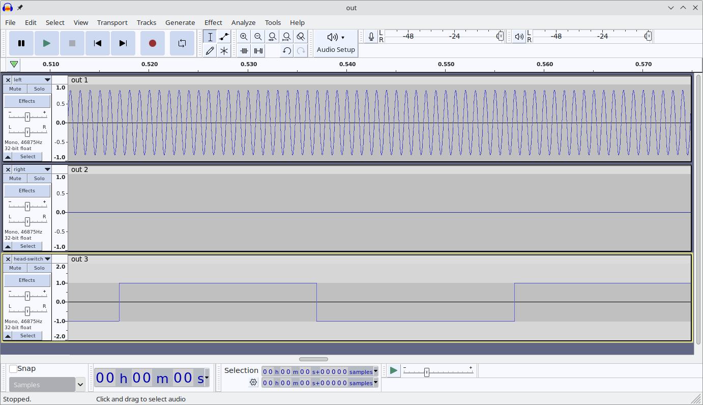
The above shows a 3ch recording as captured from the clock generator, a sine wave on the left, silence on the right, and a head-switch signal on the 3rd channel. Read on to get all the details and find out how to build one yourself.
The build and installation guide can be found over here. Have a look in the mechanical section too for some (optional) 3D printable parts. And once you built it, check out the scripts folder which holds some useful tools an examples around using this project.
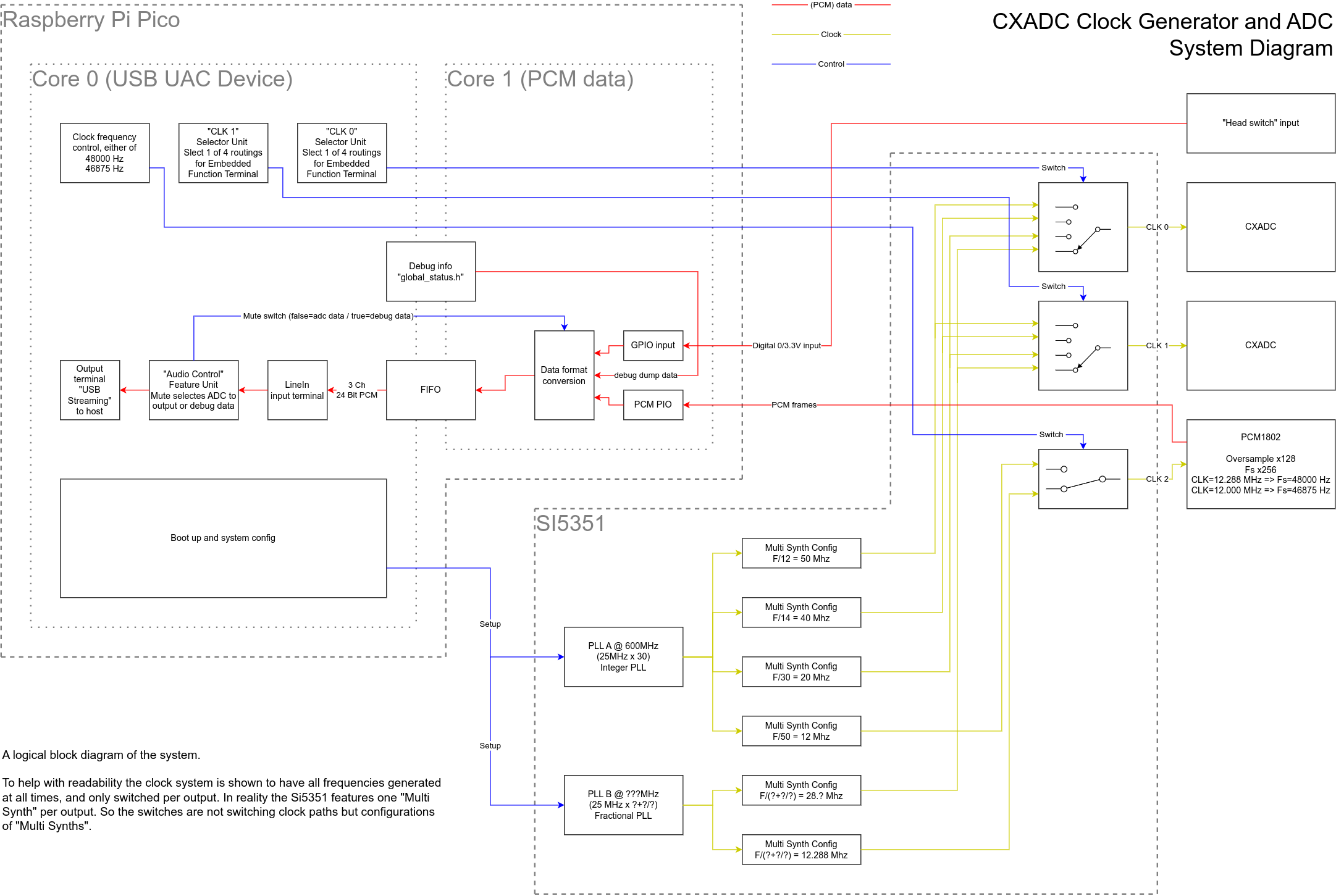
So you want to contribute, or just understand how it all works, then read on! Lets start with a logical block diagram of the system.
The brain of the system is a Raspberry Pi Pico that implements a USB UAC device (aka a usb sound card).
The USB UAC device can be used to stream the captured samples from the PCM1802 as a regular sound source.
In addition to audio streaming it also offers control over the sample rates for the ADC and CXADC cards.
USB UAC is supported by all major OS and should work without the need for any additional drivers.
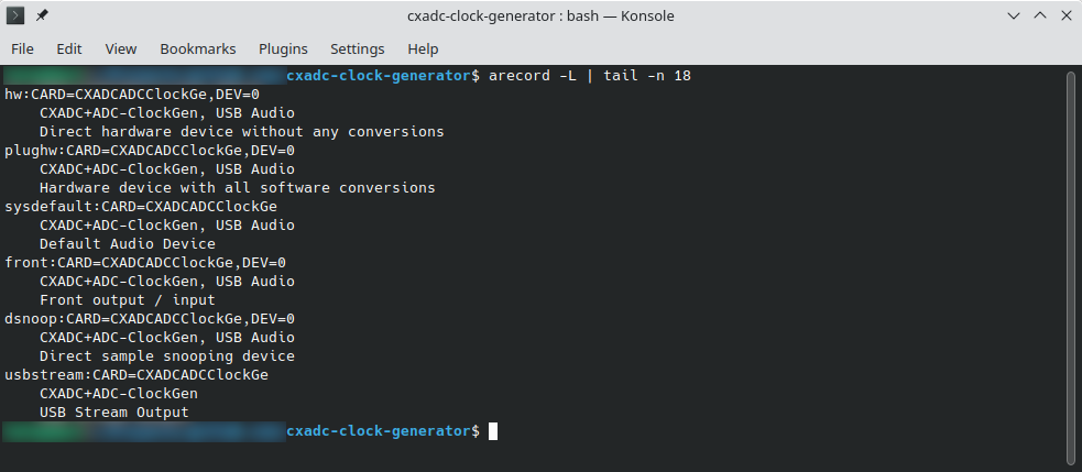
Here's the output from arecord when the clock gen is plugged in:
NOTE the following talks a lot about the implementation as a USB UAC 2.0 audio device. The backgrounds and details can be found in the "Device Class Specification Adopters Agreement", aka. the USB audio specification. So you may want to read through the first 3 chapters to get the full background.
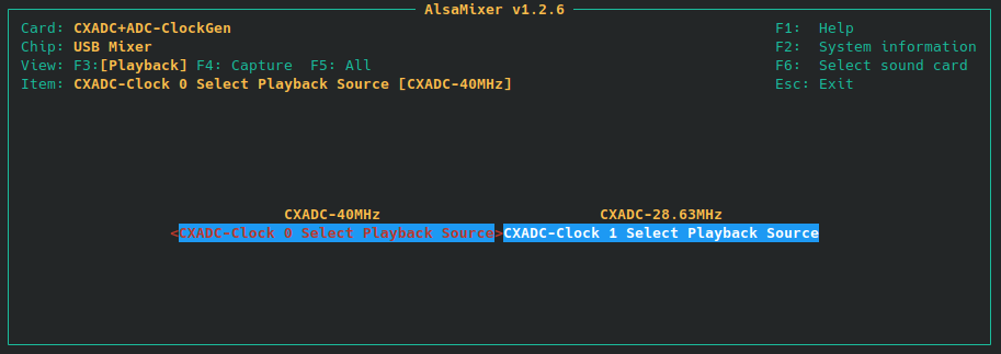
The USB UAC device offers two sample rates for the PCM1802, that can be switched via a UAC clock source. This is done automatically by your OS / sound system so just select your desired capture rate with your sound recorder of choice. To enable clock frequency switching on the CXADC cards however a UAC clock source would most likely not work. ALSA and other sound systems will configure UAC clock sources only when capturing from a linked stream. The CXADC cards however are not linked to any audio data you could stream from the UAC device. So instead the various clock rates are implemented as (fake) internal audio streams that can be switched with a UAC switch control. Internal audio streams are per UAC specification not available to the outside and as such should not trouble OS sound systems for not offering a way to stream their data. Every clock frequency is represented as one (virtual/internal/fake) input stream, and each of the two Si5351A clock output is represented as one (virtual/internal/fake) output. So to the OS / sound system this looks like a switch matrix of various audio stream sources, switched onto two outputs. This will generate entries in the usual mixer widgets / apps, that let you control your general sound card settings. But instead of switching actual audio streams, the UAC selector unit of course switches clock frequencies for the attached CXADC cards.
This is all a bit abstract, so here's how those switches are displayed in alsamixer (you can switch the rates simply using the arrow keys on your keyboard):
And here's how amixer can be used to script switching the clock rate on output 0:
To help with readability and to more closely match the USB UAC implementation, the above system diagram shows the clock system to have all frequencies generated at all times, and then switched per output. In reality the Si5351A features only one "Multi Synth" per clock output. So the switches are not switching clock paths but rather configurations of "Multi Synths".
The setup offers a couple of options for both the PCM1802 audio ADC and the CXADC, but not all of them are of equal quality. Inside the Si5351A clock generator, two PLLs are used to generate intermediate frequencies. Those intermediate clock are then further divided to get the desired clock frequencies at the 3 outputs.
PLL A is running in integer mode, which means only whole number multipliers are used, resulting in no added jitter. Further more the subsequent "multi synth" dividers are also in integer mode, again resulting in no added jitter. But this limits the clock outputs options to only frequencies that can be produced by one multiplication and one division with only whole numbers. Based on the 25 MHz source that is included on the Si5351A board, this enables CXADC sampling clocks of 20 MHz, 40 MHz and 50 MHz. The PCM1802 needs a clock of 256 times the frequency of the desired output audio sampling rate. The PLL A path generates a 12 MHz output which results in an exact (without rounding error) 46875 Hz / 46.875 kHz sample rate for the audio stream. This uncommon rate does not degrade the performance of the PCM1802 ADC and offers analog bandwidth that is above CD quality. Using common tools (sox or ffmpeg) the captured pcm data can be fully automatically resampled to the more common 48 kHz or 44.1 kHz in an offline processing step.
PLL B is running is running in fractional mode, yielding an increased clock jitter. Together with fractional configuration in the subsequent "multi synth" dividers, two more clock rates are possible. The CXADC can be clocked with the same frequency as the stock crystal 28.636360 MHz. And the PCM1802 can be clocked with a 12.288 MHz, giving the more common 48 kHz as output sample rate. In ADCs the higher the clock jitter the worse the sampling quality will be. So you should avoid these sampling rates if you can and only use the ones from the integer mode PLL A.
As this project is put together from various components (main board, sub boards, etc.), quite a few things can go wrong. The firmware will output debugging information over the UART0 on the Pi Pico (GPIO0 / Pin1). So hooking up a serial adapter is a good idea when working on the code (see also dbg.h). However when just assembling the project, users may not have the option to do that, so a more practical way of obtaining debugging info is needed. This does not have to be all the debug output that happens everywhere, but it should be enough to find common problems.
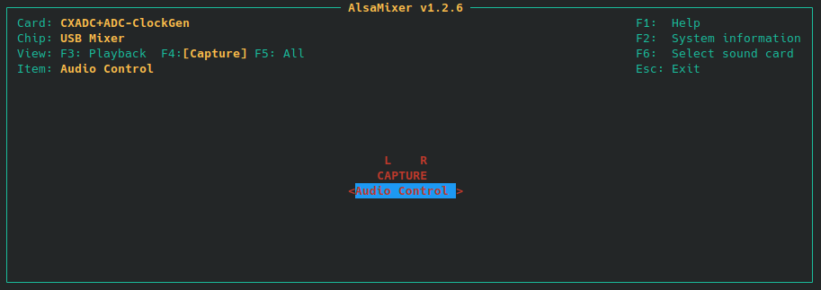
USB UAC unfortunately does not give many options to achieve that. There is a "Memory Requests" (chapter 5.2.7.1) which would be perfect, but there is no common user space tool available. User space support with regular tools is important as this is what users will have, and what the collect-info.sh script can use. So instead of writing a custom tool, we just re-use the audio data that streams from the ADC. But that can't be happening all the time, and the ADCs might even be non-working, so there must be a way to switch this on and off. This can be done with a simple mute switch on a feature unit. If muted debug info will be output, if un-muted (the default after boot), then actual ADC data will be streamed.
The above shows how alsamixer displays the on / un-muted state (can be toggled with the space bar).
Now what is inside the debug info, you may ask?
Well there is a global status object global_status.h that is updated at the relevant places in the code.
It contains flags that indicate errors, and some other values of interest.
This object is dumped in the audio data and streamed to the host.
In other words, to get the debug data, just mute the stream and record a short piece of "audio" with arecord.
Have a look at the troubleshooting section of the build guide if you need help getting the system running.
The firmware / software part is using Semantic Versioning, referring to the USB device interface. Tags on this repository will carry the firmware / software version.
The PCBs are versioned with a letter revision. These revisions do not imply any compatibility, and are solely used to differentiate one revision from another. PCB revision overview:
- VT610ex clock generator adapter
- Revision A - never released
- Revision B - first public release
- Revision C - some updates to the silkscreen and moved one via to get PcbWay support, otherwise identical to Revision C
- Revision D - update connector footprint to better fit SMA edge connector and still be compatibile with pin header edge mount
- Clock generator main board
- Revision A - first public release
- Revision B - fixes the IO VDD for Si5351, which should be 3.3V, Rev A erroneously had it at VSys
- Revision C - fixes the 3.3V from PCM1802 being driven by Pi Pico, instead this is an output and should be left open
See CHANGELOG.md.
See releases for PCB gerbers and firmware images ready to flash.
The content of this repository is under various licenses. The PCB parts are generally under Creative Commons Attribution-ShareAlike 4.0, but contains external sources (with compatible licenses). The source code is mostly under 3-Clause BSD, but contains external sources with compatible licenses mixed in. Source files carry an SPDX header to indentify. For details see the individual LICENSE* files in the respective folders they apply to, firmware zip packages contain a copy of all the applicable license files.
