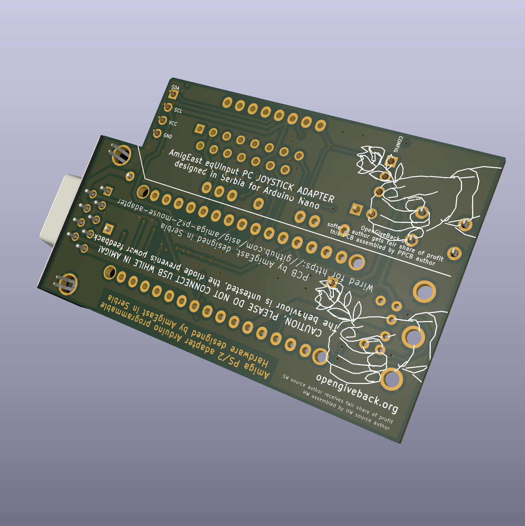
Arduino Nano based Amiga PS/2 mouse adapter PCB revision 1.7
Made with nostalgia in Serbia. :)
An experimental PCB to enable using existing Arduino Nano based sourcecode to convert PS/2 mouse to Amiga mouse signals. Also has an additional Gameport connector wired to appropriate analogue input pins on Arduino Nano, to enable connecting an analogue old PC joystick, a button (for selecting mouse resolution), and even an I2C connection for PinSockets 2.54mm, to allow for connecting other I2C devices (accelerometers or screens).
Pins were selected to suit this software opensource project : https://github.com/asig/amiga-ps2-mouse-adapter
Licensed under GPL3. The PCB is provided "AS IS", no warranties of correctness or fitness for purpose are implied nor expressed. You use the schematic on your own responsability, if you break something using it, or make stuff blow up and burn and destroy things/harm someone, it is not my fault. Use on your own responsibility. Be warned.
Caution! Please note! NEVER connect Arduino Nano to USB power source and Amiga at the same time! The design only has a diode from power source pin from Amiga joyport, to prevent powering Amiga from the device, but other considerations were not made. Take care to not draw more than 50mA, as 100mA is max. for both Amiga Joyports, and some Amigas (Amiga 500?) don't have proper protection from overdraw. Beware of excess RGB and DPI resolution in used pointing devices (if used with USB to PS/2 adapter, many USB pointing devices can be used, not all).
The Arduino Nano can be socketed to be able to reuse it for other Arduino Nano projects! Insert Arduino Nano with USB facing DB9 connector and do not connect USB cable to inserted Arduino Nano!
I also modified and used the PCB for an PS/2 to MSX mouse convertor project, tested working OK, that version is available in a separate repository https://github.com/opengiveback/eqUInputMSX
3 = P_PS2_CLK
2 = P_PS2_DATA
1 = Button MouseDPI
0 = GamePort Button1
A0 = GamePort Axis X1
A3 = GamePort Axis Y1
5 = GamePort Button2
13 = GamePort Button3
A1 = GamePort Axis X2
A2 = GamePort Axis Y2
A6 = GamePort Button4
A4, A5 = I2C connector
// Output pins 12 = P_AMIGA_V_PULSE
11 = P_AMIGA_H_PULSE
10 = P_AMIGA_VQ_PULSE
9 = P_AMIGA_HQ_PULSE
8 = P_AMIGA_LMB
7 = P_AMIGA_RMB
6 = P_AMIGA_MMB
Revision 1.7. Pullup resistors (10k) for buttons and pulldown resistors (100k) for analog lines of Gameport were added in revision 1.7.
Revision 1.6. 5v wiring was corrected for the optional gameport and i2c oled connectors.
Revision 1.5. This is a small revision of v1.1 of the design. As v1.0 had wrongly wired gnd, so wire had to be added from DB9 to gnd on the mounting hole of DB9 connector.
 If you make it and sell it, please consider I declare my opengiveback.org principle requirements at 15% (FAIR) of earnings. Check out more about my opengiveback.org concept at www.opengiveback.org
