We introduce Field Synthesis, a theorem and method that can be used to synthesize any scanned or dithered light-sheet, including those used in lattice light-sheet microscopy (LLSM), from an incoherent superposition of one-dimensional intensity distributions. Compared to LLSM, this user-friendly and modular approach offers a simplified optical design, higher light-throughput and simultaneous multicolor illumination. Further, Field Synthesis achieves lower rates of photobleaching than light-sheets generated by lateral beam scanning.
Bo-Jui Chang1,*, Mark Kittisopikul2,4,*, Kevin M. Dean1,3, Phillipe Roudot1,3, Erik Welf1,3 and Reto Fiolka1,3. "Universal Light-Sheet Generation with Field Synthesis."
- Department of Cell Biology, UT Southwestern Medical Center, Dallas, TX, USA.
- Department of Biophysics, UT Southwestern Medical Center, Dallas, TX, USA.
- Lyda Hill Department of Bioinformatics, UT Southwestern Medical Center, Dallas, TX, USA.
- Department of Cell and Molecular Biology, Feinberg School of Medicine, Northwestern University, Chicago, IL, USA.
* These authors contributed equally to this work
https://www.biorxiv.org/content/early/2018/09/26/427468
The canonical proof can be found in the supplemental information of the manuscript. Here we also have also included an illustrated proof for the Field Synthesis Theorem in the form of a MATLAB Live Script (PDF).
A more general Field Synthesis Theorem proof for the an arbitrary, non-ideal line profile (PDF)is now also available.
To retrieve code:
- Git 2.18.0 or above
For MATLAB code:
- MATLAB (2017a or above), Mathworks, Natick, MA
- Image Processing Toolbox
- Follow MATLAB link above for operating system requirements
For Python code:
- Python 3.6.2 or above
- NumPy
- SciPy
- Matplotlib
Typical Install Time: 5 minutes
git clone https://github.com/AdvancedImagingUTSW/FieldSynthesis.git
See below documentation for demonstration. Typical run time: 10 minutes
Small program to illustrate a new Field Synthesis Theorem.
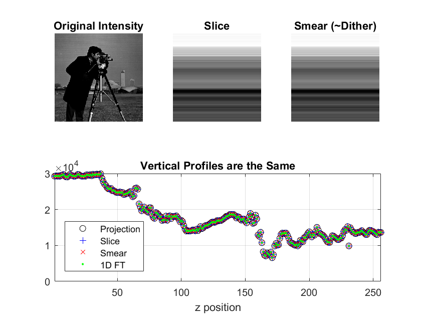
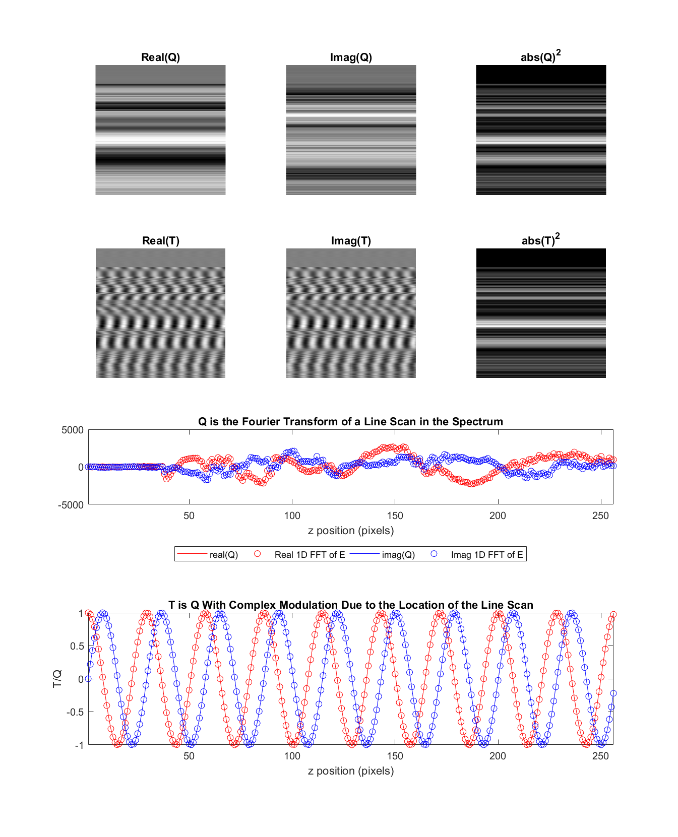
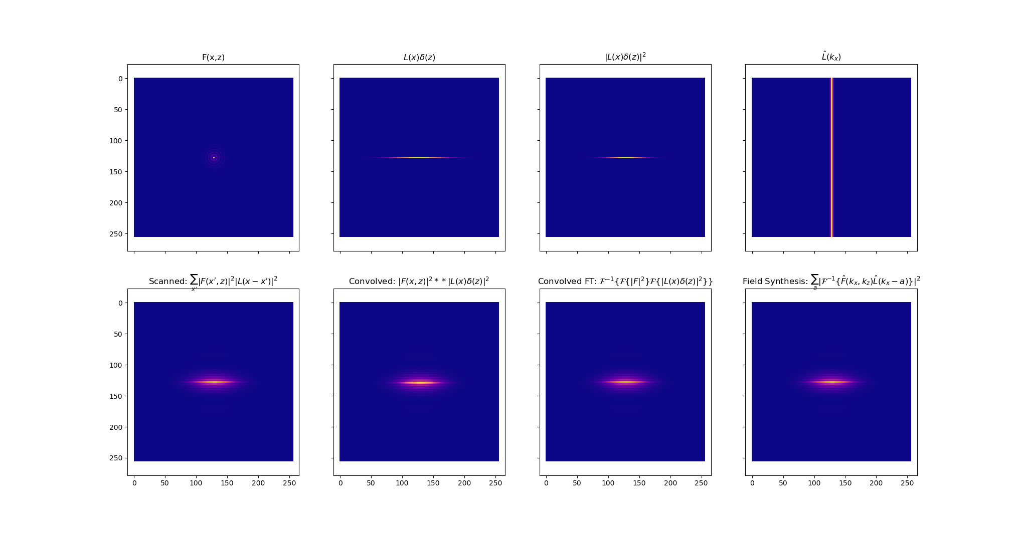
In essence it says that the projection of the absolute modulus of a complex field is the same as when one takes a sliding window in the Fourier domain, makes an inverse FFT of each slice, take the absolute modulus of that and sum it up while moving the window through the spectrum. This has important applications for scanned light-sheets and how to generate them.
Reto Fiolka, May 2017
Mark Kittisopikul, May 2017 - Aug 2018
- efield - electric field at the focal plane, may be real or complex valued
- efield - electric field at the focal plane
- slice - intensity of illumination pattern by field synthesis
- smear - intensity of illumination pattern by dithering
- Q - Fourier transform of individual line scan without phasing,a=10
- T - Fourier transform of individual line scan with phasing,a=10
FieldSynthesisTheorem.m;FieldSynthesisInteractive Create an interactive line scan demonstration of field synthesis
- mask - mask at the pupil, which is the Fourier transform of electrical field at the focal plane. zeroth frequency should be in the middle. ifftshift will be applied for calcualtions.
- doshift - if true, shift the Fourier transform of the mask so the first pixel is in the center of the image rather than the upper left
- lineProfile - line profile for the scan in the pupil mask EITHER: 1) 0 for a delta function line scan 2) a positive double value indicating the sigma of the gaussianLine in pixels 3) a line profile vector the same width as mask. The main peak is expected to be in the center and ifftshift will be applied
- hfig - handle for the display figure
- The button in the lower left plays / pauses the movie.
- The arrow buttons on the slider will move the scan by one column.
- Clicking on the trough of the slider will move the scan by five columns.
- The button in the lower right labeled R will reset the cumulative view.
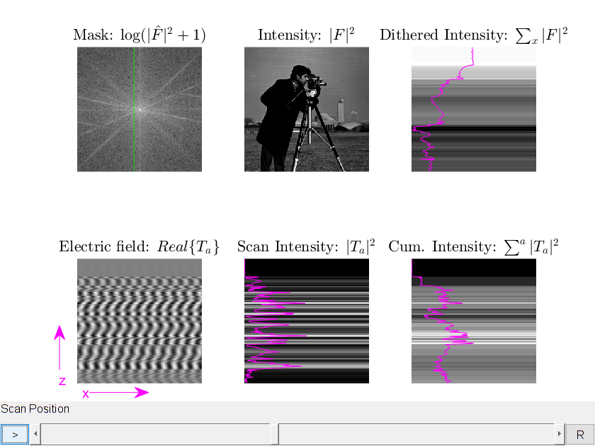
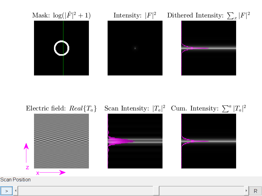
The display consists of 6 panels 1 2 3 4 5 6
- The pupil mask, |\hat{F}|^2 in log scale
- The object domain, |F|^2, scanning left to right Line plot indicates beam intensity
- Dithered, averaged intensity. Cumulative sum of display #2
- Display of the real component of the electric field of an insteaneous scan, Real{T_a}
- Instaneous scan intensity, |T_a|^2
- Cumulative scan intensity of display #5
FieldSynthesisInteractive; % default demonstration with cameraman FieldSynthesisInteractive(createAnnulus(),true); % demonstrate a Bessel beam %Create a sinc profile to emulate a scan over a finite range
N = 128;
x = -ceil(N/2):floor(N/2-1)
L_hat = fftshift(fft(ifftshift(abs(x) < 30)));
FieldSynthesisInteractive(createAnnulus(),true,L_hat);Mark Kittisopikul , August 2018
Goldman Lab
Northwestern University
Simulation for field synthesis
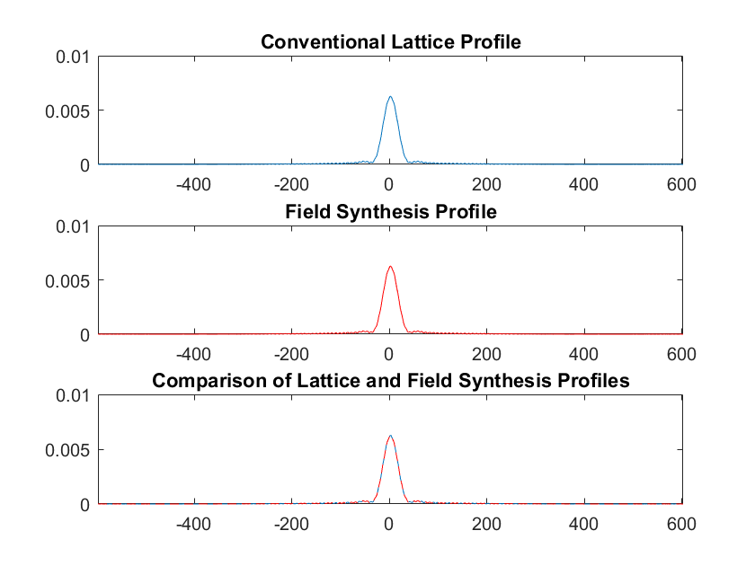
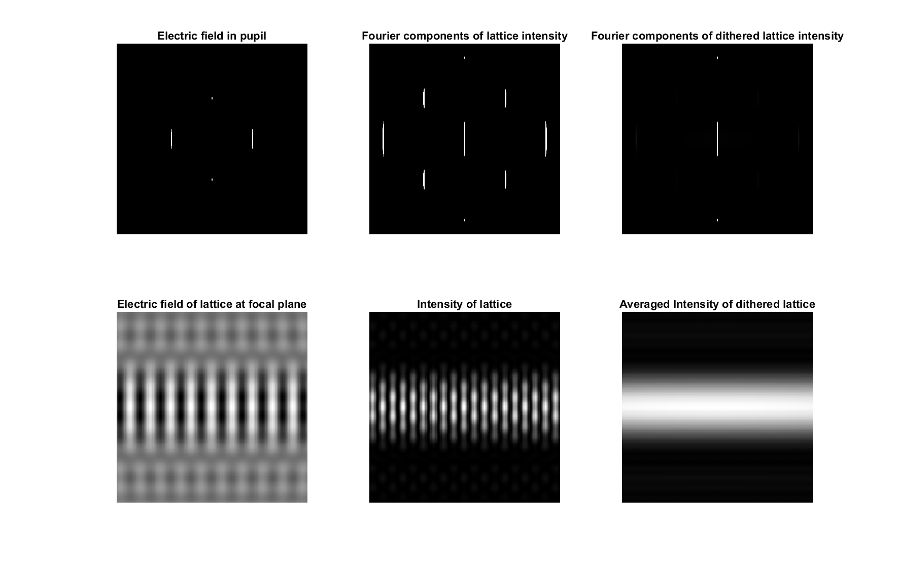
compares field synthesis vs square lattice
Reto, May 2017
Mark Kittisopikul, August 2018
- n - Defines the size of the image and mask to be n x n
- w - Width of the mask components
- r - Radius of the annulus (width is centered on the annulus)
- offset - Offset of the side components of the square lattice
- dispRange - Set which part of mask to display in figures
- out - struct containing workspace of this function
FieldSynthesisVersusLattice.m- n - size of the annular mask as a scalar, or vector with coordinates
- r - radius of the annulus in pixels
- w - width of the annulus in pixels
- annulus - n x n matrix with the annulus marked with ones
 figure;
 imshow(createAnnulus(256,32,4),[]);
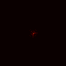
Create Bessel beam 2D profile
 figure;
 imshow(log(abs(fftshift(ifft2(ifftshift(createAnnulus)))).^2+1),[]);
 colormap(gca,hot);
caxis([0 6e-4]);This could be streamlined using the bresenham circle algorithm
Mark Kittisopikul, August 25th, 2018
Lab of Robert D. Goldman
Northwestern University
Python code - fieldSynthesis.py
From a shell:
python fieldSynthesis.pyFrom inside IPython:
 from fieldSynthesis.py import *
demoFieldSynthesis()def createAnnulus(n=256, r=32, w=4):
''' createAnnulus - create a ring-like structure
INPUT
n - size of square array or vector
r - radius of the ring
w - width of the ring
OUTPUT
an array n x n
'''def doConventionalScan(Fsqmod,Lsqmod):
'''Simulate Conventional digital scanning / dithering
INPUT
F_sqmod - Square modulus of F at the front focal plane
L_sqmod - Square modulus of L at the front focal plane
OUTPUT
scanned - Scanned (dithered) intensity of Fsqmod by Lsqmod
'''def doConventionalScanHat(F_hat,L_hat):
'''Simulate Conventional digital scanning / dithering from frequency space representations
INPUT
F_hat - Mask at back focal plane
L_hat - Line scan profile in frequency space at the back focal plane
OUTPUT
scanned - Scanned (dithered) intensity of Fsqmod by Lsqmod at front focal plane
'''def doFieldSynthesisLineScan(F_hat,L_hat):
'''Simulate Field Synthesis Method
INPUT
F_hat - Frequency space representation of illumination pattern, mask at back focal plane
L_hat - Line scan profile in frequency space at the back focal plane
OUTPUT
fieldSynthesis - Field synthesis construction by doing a line scan in the back focal plane
'''def demoFieldSynthesis():
'''Demonstrate Field Synthesis Method with Plots
INPUT
None
OUTPUT
None
'''See LICENSE.txt
Field Synthesis Demonstration - MATLAB code to demonstrate field synthesis light sheet microscopy
Copyright (C) 2019 Reto Fioka, University of Texas Southwestern Medical Center
Copyright (C) 2019 Mark Kittisopikul, Northwestern University
This program is free software: you can redistribute it and/or modify
it under the terms of the GNU General Public License as published by
the Free Software Foundation, either version 3 of the License, or
(at your option) any later version.
This program is distributed in the hope that it will be useful,
but WITHOUT ANY WARRANTY; without even the implied warranty of
MERCHANTABILITY or FITNESS FOR A PARTICULAR PURPOSE. See the
GNU General Public License for more details.
You should have received a copy of the GNU General Public License
along with this program. If not, see <https://www.gnu.org/licenses/>.
