More info on hackaday.io/project/165884-proofing-box
On startup, the screen will display the target temperature (in deg C) e.g. t: 27 meaning the target temperature is 27deg C. It will then switch to displaying the current temperature e.g. 19.60 which will update ever ~1sec.
To set a new target, enter the settings mode by pressing (holding) the switch on the rotaty encoder. The screen will display t: 27, turn the encoder to set a new target, e.g. t: 25, then press (hold) the switch to return to normal monitoring mode.
By default the relay will only change when the temperature goes significantly above or below the target (1deg C). This is to prevent the relay from constantly switching on and off.
This can be changed by adjusting the const float cushion_temp = 2.0;. Note that this is a range, so 2.0 means +1 and -1, e.g. 26~28deg C.
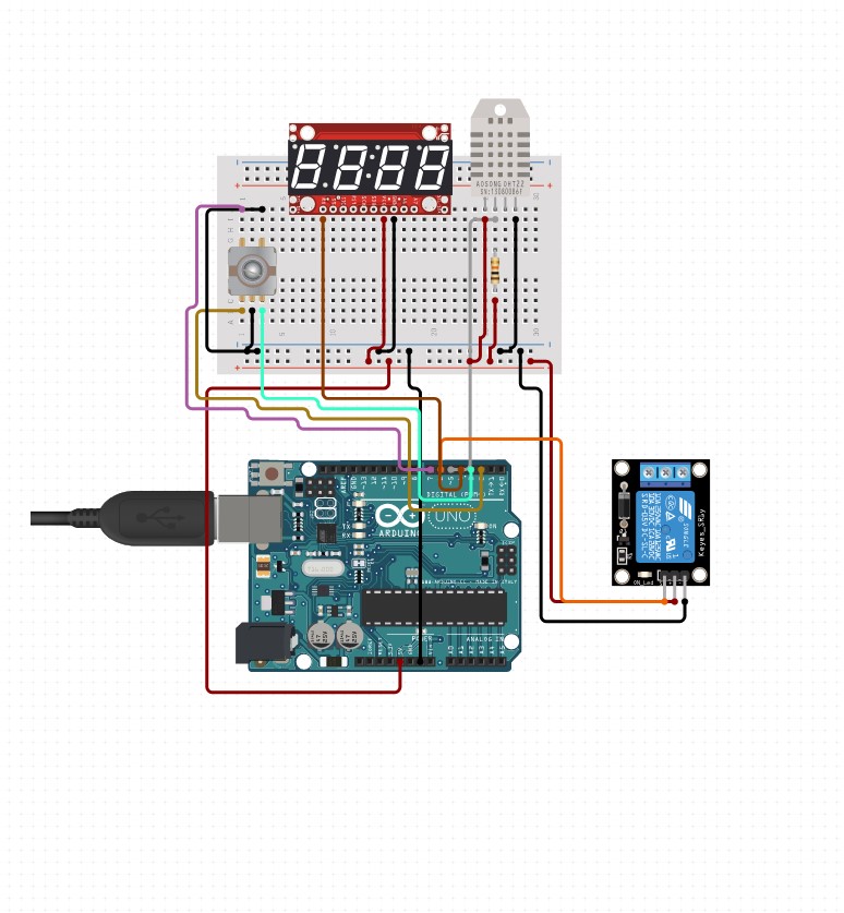
Wiring Diagram on circuit.io. Circuit.io also has wiring instructions, juct click "Project Guide" up the top.
You'll need to install a library for the DHT component. This can be done from the Arduino IDE. Tools > Manage Libraries
- DHT sensor library by Adafruit
Then click Sketch > Verify/Compile.
Assuming that worked, you can now upload the firmware to the Arduino. Click Sketch > Upload.
Note: the DHT22 I brought has an integrated 10K ohm resistor, so I did not have to wire that (unlike the diagram above). "Bus GND" and "Bus POS" are the positive and ground rails on the Breadboard.
You use (almost) any pin you like for the components, just make sure to update the corresponding const in proofing_box.ino. For example, to connect the DHT22 to pin 9, you would need to make the following change
- const int pin_dht = 5; // pin that the DHT is connected to
+ const int pin_dht = 9; // pin that the DHT is connected to- Ardunio
- GND to Bus GND
- 5v to Bus POS
- 7-Segment Display
- GND to Bus GND
- VCC to Bus POS
- RX to Arduino 4
- DHT22
- DATA to Arduino 5
- GND to Bus GND
- VDD to Bus POS
- Relay Module
- GND to Bus GND
- VCC to Bus POS
- IN to Arduino 6
- Rotary Encoder
- A to Arduino 2
- B to Arduino 3
- GND to Bus GND
- GND2 to Bus GND
- SW to Arduino 7
Warning: when you are making projects that are connected to mains voltage, you really need to know what you are doing, otherwise you may shock yourself. This is a serious topic, and we want you to be safe. If you’re not 100% sure what you are doing, do yourself a favor and don’t touch anything. Ask someone who knows!
You need to slice the cable and cut the single phase line (L), in my case this was the brown cable. One end should connect to COM (common), and the other to NO (nominally open). The neutral (N) cable should not be cut.
Heating
Pad
|
v

|####| ------------- (N)  <- AC Neutral
|####|
|####| ---- NO
            NC
            COM ---- (L)  <- AC Phase

            ^
            |
            Relay
Thanks to @greenpossum on hackaday.
If you ever need more, you might like to know prebuilt modules with everything needed except the case, are a thing. e.g.: https://www.ebay.com.au/itm/DC12V-W1209-Digital-Thermostat-Temperature-Controller-NTC-1-10K-3950-Cable/263634079376 The STM8 controller on these gadgets can be reprogrammed: https://hackaday.io/project/16097-eforth-for-cheap-stm8s-gadgets