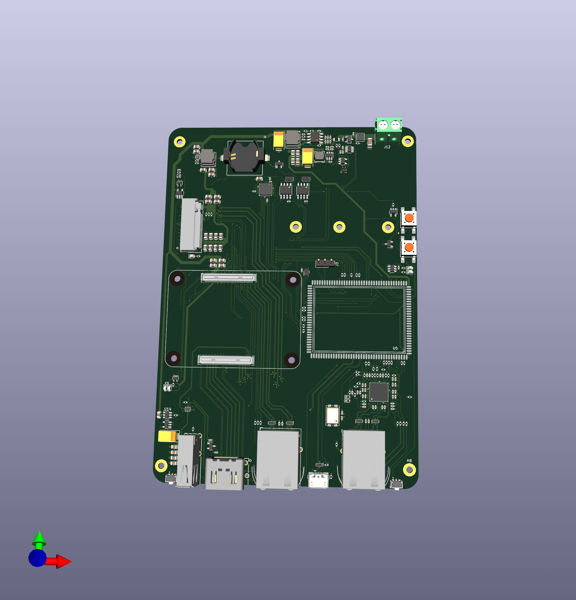
| This is a work-in-progress. No final board have been produced yet. Any part of the schematic and/or PCB could be wrong. |
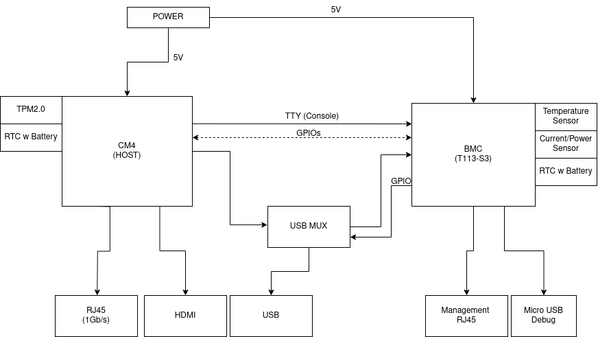
Design of the carrier board for the Raspberry Pi CM4. The main distinction from existing boards is the presence of the BMC (Baseboard Management Controller) which supposed to monitor and control the HOST, allowing the board to act as a real "server".
BMC using lots of GPIO controls the HOST: power cycle, terminal access, switches USB into OTG for flushing.

- CM4 (HOST) features:
- 1Gb/s ethernet
- HDMI
- 1 USB
- PCIe exposed as M.2 socket to connect nvme drive
- TPM2.0 (OPTIGA™ TPM SLB 9670)
- RTC with battery
- BMC features:
- Always ON
- 1Gb/s management port
- USB port for debug
- USB connection to the HOST for flushing
- I2C connection to the HOST for additional metrics
- TTY connection to HOST for SOL (Serial over LAN)
- measures Current/Power of the board
- measures Temperature of the board
- controls FAN (not available in the PoC)
BMC is based on the Allwinner T113 S3 SoM link to aliexpress.
THere are separate 5v rails for host and BMC. The host one is based on AP64501SP (5V 5A), while BMC is based on AP63205WU (5V 2A). BMC is always on. Host is being powered either by a signal from BMC or by shortening a jumper.
Main power goes through the shunt resistor connected to the power sensor (INA219A). The value is available to BMC using i2c bus.
Host has a following connectors:
- Ethernet
- HDMI
- USB
- M.2 socket M for nvme disk
BMC has a following connectors:
- Ethernet (1GB/s)
- MicroUSB (debug)
There is a connection between BMC and HOST using USB to allow flushing the HOST remotely. Since CM4 has only a single usb line, it is connected to the MUX (FSUSB42MUX) in a similar way it is done in the CM4IO board, but instead of switching client mode to microUSB, it goes to BMC.
RTC is based on PCF85063AT chip. There are two of them, one for each CPU. Even though t133-s3 has on-board RTC, it is not exposed from the SOM and reference schematic uses external one. Both chips are powered by 3.3v coming from BMC and coin cell battery.
