CardioBit is an architecture for building IoT capable, precise, scalable and cost-efficient ECG Devices. IoT-capability and affordability are the central dogmas of this architecture. This is mainly achieved by using opensource hardware, minimum reliance on specialty components, offloading signal processing tasks to the server and avoiding the use of costly isolation components - yet ensuing safety by relying solely on battery power.
In the wake of COVID-19 pandemic, in many countries throughout the world, medical infrastructure is seriously overwhelmed by a novel coronavirus. The vast majority of medical equipment are heavily patented and are sold in small volumes. Further, there is evidence that some entities actively prevented medical treatments from being deployed, even in the current pandemic. This model obviously fails during critical times. On the other hand, deployment of opensource hardware and software platforms, can result in significant cost reduction as well as increased critical preparedness. (Pearce 2020)
The potential of opensource platforms to facilitate the formation of inclusive, potentially worldwide research communities, have also captured my imagination. Economically viable solutions can be derived out of the core architecture discussed here, and can be manufactured and deployed throughout the world, in a distributed fashion. In additon, a 12-lead proof-of-concept hardware is provided.
Readers are assumed to have a minimal background in physiology and electrical engineering. Namely, they are assumed to be familiar with the basic morphological characteristics of electrocardiogram and their physiological significance, and familiarity with ohm’s law, impedance, basic circuit theory, RC analog filters and basic operational amplifier circuits. However, prospective readers are encouraged to continue, as proper reference for further consultation is given in due course. For introductory topics in cardiac physiology see (Guyton and Hall 2015), and for basic introduction to electrical engineering concepts regard (Scherz and Monk 2016) and (Mancini and Carter 2009)
The simplest model for relating the electrical activity of the heart to the body surface potentials, is the single dipole model. As an action potential propagates through the cell, in the interface of depolarizing and resting tissue, there’s an intracellular current flow in the same direction of the action potential propagation. There is also an equal extra cellular current flowing against the direction of propagation. Therefore, charge is conserved and all the current loops in the conductive media form a single field, called “dipole field” (Figure 1). (Gari, Francisco and Patrick 2006)

For modeling purposes, all the individual current dipoles can be considered to originate at a single point in space, and the total electrical activity of the heart can be represented as a single dipole, whose magnitude and direction is the vector summation of all the individual dipoles. (Madeiro, et al. 2019)

Let M(t) be the resultant vector which changes in the magnitude and direction as the function of time, potential distribution on the torso can be obtained by solving the Laplace’s equation as: (Gari, Francisco and Patrick 2006)
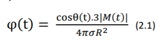
Where 𝜎 is the conductivity of the body electrolytic medium, |M(t)| is the magnitude of heart vector, θ(t) is the angle between the heart vector M(t) and the lead vector joining the center of the sphere to the point of surface potential measurement (Figure 2). Therefore, potential difference between two points in the torso can be given as: (Gari, Francisco and Patrick 2006)
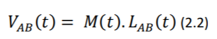
Where 𝐿𝐴𝐵(𝑡) refers to the lead vector containing different points A and B of observation (e.g., electrodes) on the torso. For more elaborate discussion regarding the derivation of the abovementioned equations, please refer to (Mark 2004)
Equation 2.2 is important, as it states that the potential vector between two given electrodes (which essentially comprises the ECG signal in the respective lead) can be reconstructed if M(t) and the angle between M(t) and the lead vector 𝐿𝐴𝐵(𝑡) are known. As demonstrated later in the proof of concepts, the reconstruction of a virtual 12-Lead ECG from a reduced lead set is attempted in software, with satisfactory results.
However, it should be emphasized that equation 2.1 is derived with the implicit assumption of body as an idealized spherical torso, as shown in Figure 2. As a matter of fact, not only torso is far from an idealized sphere, but also it has non uniform conductance 𝜎 and its impedance can change during the cycle of respiration as well. (Gari, Francisco and Patrick 2006) So, for critical applications (e.g., in critically ill, unstable patients or in studying conditions that require exact monitoring) it is highly recommended to rely on standard 12-Lead ECG as opposed to the virtual case discussed above.
In overall, this ability is helpful in that it provides the clinicians in unprivileged areas with more data without additional costs. Thus, it helps in cases which wide availability of ECG monitoring is the primary goal. For example, when secondary prevention (i.e., screening) of ischemic or heart rhythm disease is to be performed on a disperse population in a large geographic area.
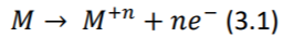
The electrical activity of the heart is propagated throughout the body by ions. To measure this activity at body surface, conversion of ions to electrons, is needed. This conversion happens at electrode-patient interface. When a metallic electrode (most commonly silver-silver chloride) is in contact with an electrolyte (skin or electrode gel), an electrochemical reaction occurs by ionexchange. Metal atoms (𝑀) tend to lose n electrons and pass into the electrolyte as metal ions (𝑀+𝑛 ) causing the electrode to become negatively charged with respect to the electrolyte: (Webster 2006)
Similarly, under equilibrium, ions in the electrolyte take the reverse direction of the equation (3.1). The electrode becomes positively charged with respect to the electrolyte as a result. (Webster 2006)
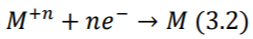
Under equilibrium condition, rate at which metal atoms lose electrons and pass into the electrolyte is exactly balanced by the rate of equation (3.2). Thus, the current flowing in one direction, cancels out the current flowing in the opposing direction, resulting in zero net current flow. However, a potential difference is found to exist between the electrode and electrolyte and depends on the position of the equilibrium between two processes (3.1) and (3.2). This potential is termed as half-cell potential, and can be calculated by the Nernst Equation (3.3) (Webster 2006)

Since an ECG signal is obtained by two equal electrodes for each lead, it can be assumed that half-cell potentials are equal and offset voltage at the input of differential amplifier is zero. In practice, small differences in the properties of electrodes result in a dc offset voltage, which can sometimes change over time. (Madeiro, et al. 2019)
 potential.")
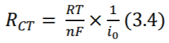
Further, as positive ions are attracted by the electrode and negative ions by the electrolyte, a double layer capacitance is created at the electrode-patient interface. Also, due to the electrochemical reactions in the interface, some dc current can leak across the double layer. The amount of leak is proportional to charge transfer resistance which is calculated by the equation (3.4) where 𝑖0 is the current flowing across the interface in both directions (no flow under equilibrium, as discussed before). The equivalent circuit is shown in Figure 3. (Madeiro, et al. 2019) Note that equations (3.3) and (3.4) are only of theoretical interest here.
DC offset voltage discussed above, can be as high as 300mV which is enormous when compared to typical 1.8mV amplitude of the ECG signal (Lee and Kruse 2008). The dc offset can be reduced by the use of high-quality electrodes or significantly suppressed with specialty circuits (Huang, Huang and Li 2018). However, in accordance with the design principles discussed in the abstract of this article, a simple rule of thumb is proposed instead: Use higher supply voltage, when designing cost-optimized solutions.
To put this design decision in better context, we need to slightly deviate from the flow of the discussion:
As ECG signal is very weak with only 0.5µV – 4mV of amplitude and is susceptible to interference [e.g., 50 or 60Hz AC noise which is present in virtually all indoor environments], it needs to be amplified before processing and analysis. (Huang, Huang and Li 2018)
A high dc offset voltage can quickly saturate a low-voltage circuit and limit the amount of achievable amplification. For example, a 3V supply voltage (equivalent to -1.5v to +1.5v dual supply), can be easily saturated by only a 5 times front-end amplification. Thus, only 2x to 3x first-stage gain can be reasonably applied. A high-resolution signal can still be obtained after a second-stage amplification and by the use of a high-precision analog-todigital converter (ADC). But as discussed later, due to low front-end amplification the noise profile will not be satisfactory. In addition, high-precision ADCs can be costly and usually have far slower sampling rates.
Thus, for designing cost-optimized solution, a supply voltage of at least 12V (-6.0v to +6.0v) is recommended. As CardioBit is designed for battery-powered operation, and high-capacity 3.7v 18650 Lithium-Ion cells are widely available with ever decreasing cost (Warner 2015), such supply voltage can be provided with 3 to 4 cells in series, allowing for a compact form-factor for the final, assembled device.
The standard 12-Lead ECG is a noninvasive representation of the electrical activity of the heart. This lead system rests on the theoretical foundation of classical lead theory introduced by Einthoven et al. (Madeiro, et al. 2019) This theory assumes a single time-varying dipole in 2- dimensional space to represent electrical activity of the heart, and assumes human body as a homogenous conductor. Later, Burger and van Millan improved and generalized the theory (Burger and van Milaan 1948) with regard to 3-dimentionality and non-homogenous conductance of the body. Yet, their theory still rests on the fixed-dipole hypothesis, thus allows for the derivation of the potentials at a given instance, anywhere on the body surface (Macfarlane, et al. 2011). As noted in Design Decision I, these assumptions are not completely solid.

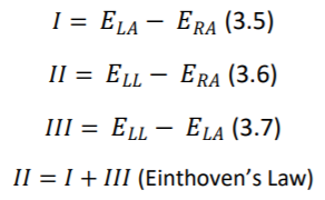
12 Leads on this system are composed of 3 bipolar limb leads(I, II, III), 3 augmented unipolar limb leads (aVR, aVL and aVF) and 6 unipolar chest leads (𝑉1 𝑡𝑜 𝑉6). Bipolar limb leads are defined by equations 3.5, 3.6, 3.7. (Figure 4). Right leg electrode is used for reducing electromagnetic interference, and can be placed anywhere at body surface. It is placed at right leg for convenience. (Madeiro, et al. 2019).

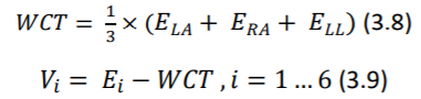
Potentials of unipolar chest electrodes (𝑉1 𝑡𝑜 𝑉6) is measured relative to Wilson Central Terminal (WCT), which is the normalized sum of the potentials of 𝐸𝐿𝐴, 𝐸𝑅𝐴 and 𝐸𝐿𝐿. (Equations 3.8 and 3.9) (Madeiro, et al. 2019)

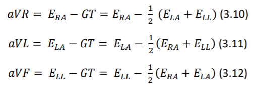
Augmented unipolar limb leads, comprise the remaining three leads. The same set of electrodes from bipolar leads are used (𝐸𝐿𝐴, 𝐸𝑅𝐴 and 𝐸𝐿𝐿) as positive electrodes and negative electrode is a modified version of the Wilson Central Terminal called of GT. (equations 3.10 through 3.12) (Madeiro, et al. 2019)
🎯 Design Decision III: Technical issues should be openly discussed, anyone’s contribution is to be welcomed
A variety of other lead systems are proposed, including Frank, reduced Frank, EASI or various three or two lead configurations. (Gari, Francisco and Patrick 2006). But the standard 12-Lead system has by far the widest adoption in clinical practice. Thus, other configurations are not discussed further.
However, CardioBit is opensource in hardware and software and it can be adopted for any given lead set, by any interested researcher. In fact, as the author, I’ll be delighted If I see such actions taken by the potential research and development community. I believe community, can shed more light on the issue of practicality of virtual 12-Lead ECG reconstruction from a reduced lead set, provide a quantitative measure of accuracy for such reconstructions, or even come up with a more theoretically solid method of reconstruction (e.g., based on the modern concept of leadfield instead of lead-vector)
In that spirit, I like to echo a section of ST Segment Monitoring Practice Guideline Working Group’s recommendation regarding the use of reduced lead sets, which is further discussed by (Gari, Francisco and Patrick 2006):
- If only two leads are available for ST segment monitoring (for patients with acute coronary syndrome), lead III and V3 should be used.
- The best three-lead combination is III-V3-V5
- V1, is considered the best lead to monitor for cardiac arrhythmias
- The use of at least three chest leads (V3, V4, V5) is recommended for ST analysis
The provided proof-of-concept of the CardioBit platform’s core architecture, is designed for acquisition of 2 bipolar limb leads and 2 unipolar chest leads. User (whether clinician, researcher or developer) can decide which respective two leads he or she wants to use. As noted, reconstruction of virtual 12-lead ECG from the chosen leads is attempted in software. It is left up to user to decide whether to use this feature or not. For more information, please regard the factors noted in Design Decision I
")
As stated before, surface potentials representing ECG signal are very weak (a few millivolts maximum) and are riding on a comparatively enormous offset voltage (hundreds of millivolts). (Lee and Kruse 2008) To complicate matters further, these signals are often contaminated with biopotential activity of muscles and nerves beneath the electrodes, 50Hz/60Hz AC powerline interference, low frequency motion artifacts and all sorts of high frequency electromagnetic noise (Madeiro, et al. 2019)
Among these parasitic sources, the AC interference may be the most troublesome. Low frequency motion artifacts can be dealt with by good skin preparation and good electrode adhesion. Also, biopotential artifacts of nerve and muscle activity will be negligible if patient remain still and relaxed at a comfortable position. Lastly, high frequency noise, can be easily suppressed by a simple analog RC filter and later by digital filtering. Conversely, AC interference is present virtually anywhere and its frequency falls in the normal frequency range of ECG signal (0.05Hz – 250Hz)
Unfortunately, AC interference is unavoidably present in any clinical situation. This interference can be of two independent types: magnetic and electric: A changing magnetic field produced by AC powerlines can induce in any nearby conductive loop, an electromotive force, which results in an ac potential. A changing electric field can also produce interference by causing ac currents to flow to ground through the system. (Huhta and Webster 1973)
The magnetic interference is directly proportional to the area of the loop formed between two electrode leads and reducing this area is the best way to reduce this type of interference. Expensive shielding of the wires does not prevent this kind of interference. (As shown in Figure 8.) (Huhta and Webster 1973)
")
The electrical interference is modeled as the capacitive coupling of AC powerlines to lead wirings, which results in displacement current induced in the respective leads, because the length of the leads is almost the same and the wires run closely together, this displacement current should be approximately equal in each lead. (Huhta and Webster 1973)
Assuming that electrodes have perfectly the same electrical impedance, such displacement current should be rejected. Because, the front-end differential amplifier, only amplifies the difference between the voltages of the two inputs. In other words, as impedance of both electrodes is the same, the displacement current, results in induction of exactly the same voltage in them. This can be easily stated using generalized ohm’s law (Equation 3.13).
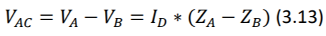
Where 𝑉_𝐴𝐶 is the AC interference potential, 𝐼_𝐷 is the displacement current and Z is the impedance in respective inputs A and B. It is observed that 𝑉_𝐴𝐶 is induced by unbalance of the two impedances (the term 𝑍_𝐴 − 𝑍_𝐵 being non-zero). (Huhta and Webster 1973)
That being said, it should not come as a surprise, that no two electrodes are perfectly the same in real world. Electrode impedance at 60Hz may range from less than 1 KΩ up to 100 KΩ. Given typical values of 6 nA of 𝐼𝐷 in a 3-m length of unshielded wire, and typical impedance imbalance of 5KΩ, induced potential (𝑉𝐴𝐶) would be about 30µV which is roughly 3 percent of the ECG potential. (Huhta and Webster 1973)
Author should note here that in the experimentation with lower quality, cheaper disposable electrodes, far higher impedance imbalance has been observed and induced potential frequency observed to be as much as 10% of the QRS potential. Such observations influenced the Design Decision IV which will be discussed in due course.
")
- Twisted cables minimize the area occupied by the loop forming between electrode leads and the body, thereby reduce the magnetic interference of AC powerlines. As discussed in the section 3.3.1 and shown in Figure 8. Shielding provides a measure against electrical interference of AC powerlines, by providing a grounded surface near the lead wires, thereby significantly reduces capacitive coupling of powerlines with lead wires. Consult (Huhta and Webster 1973) for more detailed discussion.
- Instrumentation Amplifiers are modified types of operational amplifiers. They are differential amplifiers with a very high (theoretically infinite) input impedance and improved CMRR. This large input impedance, is essential to ensure no current is being drawn from the body, and thus the small voltage of ECG signal is properly measured. In short, the chain of reasoning for this, is very similar to that of well-known ideal voltmeter, which should have infinite resistance and no current should flow through it. See (Horowitz and Hill 2015) or (Scherz and Monk 2016).
- Common-Mode Rejection Ratio (CMRR) indicates the ratio between the differential gain of an amplifier (𝐺𝐷) and its common-mode gain (𝐺𝐶). (Equation 3.14) Common mode signals are those that appear simultaneously on both inputs (e.g., that of 60/50-Hz powerline interference). Ideally, CMRR of a differential amplifier should be infinite. However, that’s not achievable in practice. Instrumentation amplifiers enjoy a higher CMRR than those of ordinary operational amplifiers, due to their special configuration. The value of CMRR changes with gain and frequency, and typically ranges between 80dB to 120dB. See (Horowitz and Hill 2015).
- Last to be noted under this topic, is the necessity of pre-amplification per se. As discussed before, the desired ECG signal is very weak and is floating on a large-by-comparison voltage offset, created by unequal Nernst potential in respective electrodes. This limits the amount of gain applicable to the first stage amplification. In addition, low frequency noise resulting from poor skin preparation or poor electrode adhesion can further complicate the problem. Thus, a large first-stage gain would result in quick saturation and/or large wandering of output signal of the circuit. Dividing amplification in two stages, can significantly alleviate these problems and yet adequately amplify the signal to meet the dynamic range of analog-to-digital converter. (Madeiro, et al. 2019)
- Author proposes a coarse rule of thumb for determining first-stage gain: divide supply voltage by 0.3 and do not exceed one-fourth of the result. For example, a supply voltage of 12v (+6v to -6v) should have maximum first stage gain of ( 12/0.3 × 1/4 = 10). The divisor 0.3 comes from taking into account a typically high electrode offset voltage of ∓ 300mV. It is divided by four to ensure amplified offset does not saturate more than half of negative or positive voltage rails.
- This circuit inverts and amplifies the common-mode voltage and feeds it back to the body. As a result, it can help to reduce noises that are induced on both of the electrode leads (e.g., AC powerline noise). (Madeiro, et al. 2019) Unfortunately, this circuit can easily become unstable, and thus not implemented in CardioBit proof-of- concept hardware (more on the reason in Design Decision IV). This circuit is extensively discussed in literature and interested readers are referred to (Webster 2006)
- Safety precautions should be taken seriously when a circuit that is connected to the mains electricity, comes into contact with human subject. Even very small current leakages (less than 100µA) can induce lethal ventricular fibrillation in catheterized human subjects.
- In such circumstances, circuit board must be segmented into isolated and non-isolated sections. These sections must be separated by at least 10mm of free space from each other (depending on the dielectric constant of the PCB) Isolated sections should receive power from non-isolated section via DC-to-DC converters. Similarly, information (ECG signal) is transmitted back to the non-isolated parts through opto-isolators or isolation amplifiers. (Gari, Francisco and Patrick 2006)
- ⚠ As discussed in the Design Decision V, and in accordance with the design principles discussed in the abstract, CardioBit, is designed ONLY for low-voltage DC battery-powered usage. The proof-of-concept circuit is not isolated and should not be directly (via AC-to-DC adapter) or indirectly (via USB port to a mains-powered PC or even a laptop that is connected via an adapter to AC power) connected to the wall outlets, unless it is completely disconnected from human subject. The operator, is responsible for any shortcomings in protecting patient safety, when he or she ignores these precautions.
- As CardioBit is opensource, any community developed hardware is advised to come with precise documentation clearly describing the specific solution’s do’s and don’ts regarding patient safety.

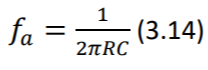
- As previously discussed, half-cell potential differences at electrodes result in a DC offset which gets amplified in the first stage and can possibly saturate the voltage rails if high amplification is applied. In addition, changes in skin moisture, temperature, muscle tremor, movement, electrode gel leakage and patient’s breathing, result in slowly varying electrode impedance which manifests itself as a slow wandering of the ECG baseline. (Madeiro, et al. 2019) A simple RC filter can ground the signals below a cutoff frequency 𝑓𝑐 , which is determined by choosing the values of the resistor R and the capacitor C. (Equation 3.14) However as discussed in (G), using an active filter might be a better option.
- As high-pass filter, removes the effect of offset voltage, higher amplification can be achieved in the second stage. The amount of the amplification should be determined by both considering supply voltage of the circuit and dynamic range of the analog-to-digital converter. One must ensure a high-voltage QRS complex would not saturate the voltage rails. Minimum amplification for a desirable dynamic range can be determined by looking for the u-waves in the acquired signal. If these waves are readily recorded, it can be reasonably assumed that amplification is sufficient for analog-digital converter to faithfully record the signal.
- As high-pass filter, removes the effect of offset voltage, higher amplification can be achieved in the second stage. The amount of the amplification should be determined by both considering supply voltage of the circuit and dynamic range of the analog-to-digital converter. One must ensure a high-voltage QRS complex would not saturate the voltage rails. Minimum amplification for a desirable dynamic range can be determined by looking for the u-waves in the acquired signal. If these waves are readily recorded, it can be reasonably assumed that amplification is sufficient for analog-digital converter to faithfully record the signal.
")
- high frequency electromagnetic interference, and skeletal muscle activity, can also contaminate the recorded biopotential, especially during exercise or under 24/7 continuous (Holter) monitoring. These high frequency components should be filtered, in a way that does not cause distortion on ECG signal (e.g., blunting of the QRS peak). Attempting to rely solely on the slow sampling frequency of analog-to-digital converter (ADC), to filter such components, will result in a signal corrupted by aliasing effect. Refer to (Parker 2017) for an introduction.
- In order to avoid aliasing, Nyquist theorem dictates the cutoff frequency of the low pass filter (equation 3.14) should be less than half the sampling frequency of ADC. Kligfield, et al. suggested 0.05 Hz to 250 Hz to be the frequency band of desired ECG signal. If adult patients are under monitoring, the cutoff of the lowpass filter can be reduced to 150 Hz. So, the ADC must feature a sampling frequency of at least 301 Hz.
- A simple low-pass filter is used in the proof-of-concept of the core architecture. But theoretically, this may not be a good choice. First, simple RC filters suffer from a poor rolloff of about -20 dB/decade. Meaning signals with 10 times the frequency of filter’s cutoff will still be present with one-tenth of original voltage. So, noises which have frequencies close to the cut-off, will remain significant and may still cause prominent aliasing to occur.
- High-order active filters can instead be used with more ideal performance, but designer needs to beware occasional ringing behavior near cut-off frequency. High-order Bessel filters are recommended for their linear response and minimal distortion (Madeiro, et al. 2019). I avoid discussing details here, as they are far from the scope of this article. However, in Design Decision IV, I discuss why simple RC filters are used in core architecture’s proof-of-concept.
- Lastly, the acquired biopotential will be converted to digital representation by a delta-sigma analog-to-digital converter, with a sampling frequency of at least twice the cut-off frequency of the low-pass filter. The digital signal will be further processed with embedded microcontroller (Based on Arduino or ESP8266 platforms) as discussed later.
This design decision, has been referred to, as early as Section 3.3.1, in relation to the issue of impedance imbalance of low-quality electrodes, and later, in 3.3.2 (C), in relation to right-leg circuit, and then, in 3.3.2 (G) in relation to RC filters. However, actual presentation of this designdecision has been delayed until now, because sufficient background should have been discussed for it in order to make sense.
The design decision IV is about the approach to noise-suppression. As we learned, ECG signal is inevitably contaminated by noise. The issue is how to filter out and suppress the noise, without distorting the signal. Additionally, the core-architecture should be open-source, inclusive and cost-optimized. So, the solution, should not be overly elaborate, as it discourages contribution. Less-privileged users should also be kept in mind, so worst-case scenarios of poor-quality electrodes with large offset voltage and high impedance imbalance should be assumed throughout the design.
As a result, author decided against the use of right-leg drive circuit, as it is unstable by design and requires fine-tuning or fancy design techniques to work properly, which reduces scalability and inclusivity of platform.
In the same spirit, simple first-order RC filters have been preferred over more complicated eighth-order active Bessel filters. However, in this case, the compromise sometimes manifests itself. Unfortunately, designer is sometimes forced to reduce cut-off frequency of the low pass filter below 150 Hz, to prevent aliasing in cases where sampling frequency of ADC is close to 300- Hz (which is not a rare issue in low-cost ADCs). Also, the R wave in the QRS complex may become mildly blunt, which may be tolerable in some applications, but not in some others.
Such analog minimalism, will be later met with aggressive digital signal processing, on the server side, which can be flexibly tuned by the user through a web-based user interface. For example, User may enable, disable or set filtering frequency, etc. Please refer to (Parker 2017) for theoretical introduction on the subject. For enquiry about the detailed implementation of these features, please refer to the proof-of-concept hardware documentations.
In overall, this decision may render the bare-bone, core-architecture unsuitable for some critical research or clinical applications. But then again, that’s not the intended use-case. The core architecture is designed as a starting platform for other solutions to be built upon it. I believe, overtime, a vibrant community can more than compensate such technical shortcomings. So, one must design the core platform as generic as possible, rather than prohibitively opinionated and elaborate. Later, more complete products can be made based on the core platform.
CardioBit is also designed with a look toward distributed manufacturing. The casing, provided for the proof-of-concept hardware, can be readily made with a 3D printer, the PCB can be prototyped for just a few dollars and can be assembled in any electronicslaboratory with minimal equipment. Anyone, anywhere in the world can tweak the proof-of-concept hardware, or improve the design to make it more suitable for specific applications.
With this great customizability, comes great concernsfor patient safety. As previously stated, less than 100µA of 60-Hz AC leakage current, can result in lethal consequences in catheterized patients. Although measures can be taken to ensure such leaks will not happen (e.g., by electrical isolation of the analog front-end and the use of isolation amplifiers), and healthy, nonhospitalized individuals, may have higher thresholds and less vulnerability, one cannot simply hope that all the design guidelines will be properly implemented in community-designed solutions. In this regard, the risk is simply too great even for minor mistakes.
Thus, it was decided against the use of AC power, altogether. The core architecture along with its proof-of-concepts are designed ONLY for battery-powered operation. They should not be connected to mains powerlines, either via the charging adapter, or via USB port to an AC powered PC or even a charging laptop. Developers who want to use the USB port to test their prototypes, are advised to use an isolated USB hub to minimize dangers.
I believe this design decision, not only results in far better patient safety, it also honors the design principles, as the total cost of both components and development will be driven significantly lower. This way, the platform will be far more forgiving in case of design/assembly errors and so it will remain inviting to young, less experienced minds.
Additionally, in the long run, lithium batteries will become even more affordable, developed products will become more energy-efficient, and more portable, and can be used in remote locations and unprivileged off-grid areas.
CardioBit platform, does not use custom digital circuits, and it is designed to be compatible with open-source electronics platforms like Arduino. Arduino is an open-source, easy to use hardware and software platform. The Arduino-based boards are readily available virtually everywhere in the world in multiple form-factors with affordable prices.
Originally, Arduino is based on 8-bit AVR microcontrollers. But as hardware is opensource, versions based on ESP8266 32-bit processor are also developed based on Arduino platform. This chip is more powerful, and features more memory, along with full TCP/IP stack for Wi-Fi connectivity. Many open-source libraries are developed for this chip to be programmed with Arduino software, using Arduino integrated development environment (IDE) and Arduino programming language.
CardioBit is not opinionated about which platform, or microcontroller is used for further processing. One can use Arduino, Raspberry Pi, Orange Pi, CircuitPython or essentially any open or closed-source platform to pair with the analog front-end. Only requirements are to power the ADCs used in the circuit with native voltage of the platform (3.3v or 5v), choose the value of endstage resistors to divide the voltage to the suitable value, and connect to ADCs with a communication interface (e.g., SPI or I2C). Connectivity to internet should also be provided, either natively or by using Wi-Fi or Ethernet shields, as digital signal processing is offloaded to server-side.
However, to be on par with our design principles, we based the proof-of-concept models for the core-architecture on ESP8266 powered hardware and Arduino platform software. Low-cost, lowpower, readily available ADS1015 ADC chips are used and accessed via I2C. These can be directly swapped with ADS1115 chips for low lead-count solutions, as this has higher accuracy but lower sampling rate which renders it too slow for 12-Lead devices.
As already stated, multiple times, CardioBit core architecture and its proof-of-concept implementations are designed ONLY for battery-powered operation. Operator is solely responsible for patient safety if he or she uses the device while it’s plugged into AC power adapter or non-isolated computer USB port. (Please refer to Design Decision V)
Also, the core architecture and its proof-of-concept implementations, are not equipped with voltage-limiting input circuitry, and should not be relied upon in mission-critical applications, especially when defibrillators or other electrosurgical equipment are to be used. In such cases, high-voltage induced between two leads by such equipment, can damage the internal circuits and render the device non-working.
- Burger, H.C., and J.B. van Milaan. 1948. "Heart-vector and leads, Part I." British Heart Journal
- Einthoven, W, G Fahr, and A DE Waart. 1950. "On the direction and manifest size of the variations of potential in the human heart and on the influence of the position of the heart on the form of the electrocardiogram." American Heart Journal
- Gari, D.C., A. Francisco, and E Patrick. 2006. Advanced Methods and Tools for ECG Data Analysis. Artech House, Inc.
- Guyton, Arthur C., and John E. Hall. 2015. Guyton and Hall Textbook of Medical Physiology. Saunders.
- Horowitz, Paul, and Winfield Hill. 2015. The Art of Electronics 3rd Edition. Cambridge University Press.
- Huang, Ji-Wei, Tai-Ming Huang, and Fan-Yang Li. 2018. "Design of a low electrode offset and high CMRR instrumentation." IEEE.
- Huhta, James C, and John G Webster. 1973. "60-Hz Interference in Electrocardiography." IEEE Transactions on biomedical engineering.
- Kligfield, P., L.S. Gettes, J.J. Bailey, R. Childers, B.J. Deal, E.W. Hancock, G. van Herpen, and Kors. 2007. "Recommendations for the Standardization and Interpretation of the Electrocardiogram." Circulation.
- Lee, Stephen, and John Kruse. 2008. "Biopotential Electrode Sensors in ECG/EEG/EMG Systems." Analog Devices.
- Macfarlane, Peter W., Adrian Van Ooosterom, Olle Pahlm, Paul Kligfield, and Michiel Janse. 2011. Comprehensive Electrocardiology, Second Edition. Springer.
- Madeiro, Joao Paulo do Vale, Paulo Cortez, José Maria Da Silva Monteiro Filho, and Angelo Roncalli Alencar Brayner. 2019. Developments and Applications for ECG Signal Processing. Academic Press.
- Mancini, Ron, and Bruce Carter. 2009. Op Amps for Everyone. Newnes.
- Mark, Roger. 2004. Quantitative Physiology: Organ Transport Systems, Lecture notes from HST/MIT Open Courseware .
- Parker, Michael. 2017. Digital Signal Processing 101. Newnes.
- Pearce, Joshua M. 2020. "A review of open source ventilators for COVID-19 and future pandemics [version 2; peer review: 3 approved]." F1000Research 3,4
- Scherz, Paul, and Simon Monk. 2016. Practical Electronics for Inventors. McGraw-Hill Education.
- Warner, John. 2015. The Handbook of Lithium-Ion Battery Pack Design. Elsevier Science.
- Webster, John G. 2006. Encyclopedia of Medical Devices and Instrumentation. Vol I. Wiley-Interscience.