⚠️ This software defaults to transmit on the 915MHz ISM band legal in the United States. Transmitting on this band may not be legal in your country.
 $ git clone --recurse-submodules https://github.com/jpaximadas/YeeNet.git
 $ cd YeeNet
 $ git config core.hooksPath git-hooks # Only necessary if you plan on contributing
 $ export YEENET_BOARD=BLUEPILL_F103
 $ make -C libopencm3
 $ make -C src
If you have an older git, or got ahead of yourself and skipped the --recurse-submodules
you can fix things by running git submodule update --init (This is only needed once)
If you are targeting development board other than the STM32 "Blue Pill", change YEENET_BOARD accordingly. For a list of supported boards, see Supported Boards
Subsequent changes to the source files only require make -C src
This repository uses the stlink open source STM32 MCU programming toolset: https://github.com/stlink-org/stlink
- Ensure BOOT0 is not set such that the board will erase the memory after a reset
- Ensure SWDIO, SWCLK, and GND are connected to the MCU (only connect 3.3V if you intend to power the board from the programmer)
- Program the chip:
$ cd src
$ make upload
OpenOCD is an alternative to stlink but is not supported by make upload.
Once the binary has been uploaded run the following in the the src directory:
- Start the gdb server
$ ./st-util
- In another terminal--still in src--start GDB and configure
$ gdb yeenet_router_firmware.elf
$ set processor armv7
$ target remote localhost:4242
$ load yeenet_router_firmware.elf
Further GDB on STM reading:
Note that this pdf uses the STMCube GDB server, not the open source stlink one. However, from the perspective of the GDB client, there isn't a difference. Page 6/15 of the pdf shows how to use breakpoints and watchpoints.
There are serial drivers in development here: https://github.com/jpaximadas/yeenet-router-driver-python
- src contains the program
- shared contains shared files from libopencm3
YeeNet aims to target readily available and low-cost STM32 development boards. See below for a table of supported targets and their corresponding YEENET_BOARD value.
| Board | YEENET_BOARD |
|---|---|
| Blue Pill STM32F103 | BLUEPILL_F103 |
| Black Pill STM32F411 | BLACKPILL_F411 |
Support for other boards can be added by creating an appropriate platform definition in platform/ and updating yeenet.mk accordingly.
The following table shows how the pins on supported development boards should be connected to the SX127x and USB to UART. Please read the warnings at the end of the section before attempting to the breadboard this.
| Function | Blue Pill/Black Pill Pin |
|---|---|
| Serial TX | PA9 |
| Serial RX | PA10 |
| IRQ | PA0 |
| MOSI | PA7 |
| MISO | PA6 |
| SCK | PA5 |
| CS/SS | A1 |
| RST | B9 |
| Address Bit 0 | B10 |
| Address Bit 1 | B11 |
- Serial TX/RX should connect to a USB/UART chip.
- IRQ should connect to DIO0 on the SX127x. (May be called D0 or G0 on a breakout board)
- MOSI,MISO,SCK, and SS should connect from the dev board to the appropriate pins on the SX127x breakout.
- RST should connect from the dev board to the appropriate pin on the SX1276x breakout.
- Address bits 0 and 1 should run from the dev board to 3.3v or ground.
⚠️ Do not power the board from more than one voltage source. This will damage the regulator on the PCB.
⚠️ Power the SX127x or SX127x dev board with 3.3 volts ONLY. The layout of the pins above routes signals from the SX127x into pins of the bluepill that are NOT 5 volt tolerant. The Adafruit SX127x breakout will emit 5 volt logic signals and damage the bluepill if powered from 5 volts.
- Power the bluepill from 5 volts from the USB to UART. The bluepill will regulate this down to 3.3 volts for its own use. Alternatively, the bluepill may be powered with 3.3 volts from a regulator on the USB to UART.
- Power the SX127x from a decent 3.3 volt regulator. The bluepill's 3.3 volt regulator is not good enough for the task. Use the one on your USB to UART if it's present.
- Leave 3.3 volts on the ST-Link programmer disconnected.
- Work on packet handler
- Improve failure mode when an ack arrives late
- How do acks affect the packet handler when working with unacked packets
- Does TX snooze feature work?
- Prevent packet_handler from dereferencing tx_pkt null pointer immediately after setup when RX'ing a nack?
- Provide higher layers function to move location of rx_pkt pointer in packet_handler
- Write packet router
- Implement USB and retain UART functionality
- Write up documentation
- Improve backoff_rng in packet_handler so it doesn't exhaust the entropy pool quickly
- Improve organization of hardware setup
- Start repo for user interface (use dear imgui)
- Add SX127x FSK functionality to modem_xl.c
The adafruit breakout board can occupy too much space to access all the pins and can be expensive. You can obtain a bare breakout board here:
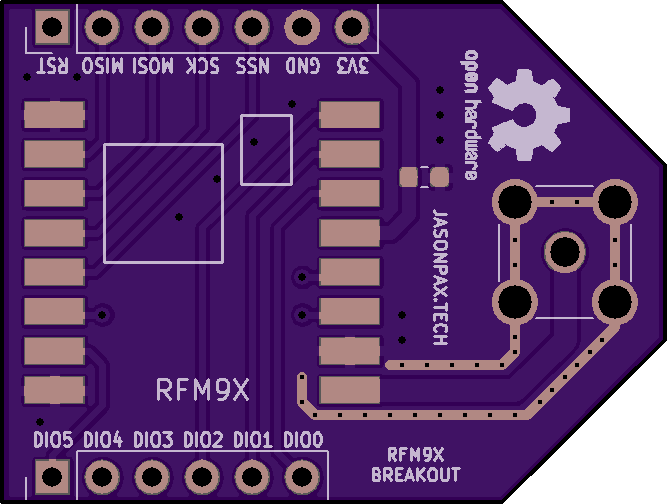
The RFM95 radio module can be obtained from aliexpress or banggood for under five dollars a piece.
- The reset pin on the adafruit breakout board must be held LOW in order for the device to function, contrary to the instructions on the adafruit website.
- The reset pin must be pulled low momentarily in order to reset the device when the mcu reboots. This guarantees registers are reset to the original state. Failing to do this can cause weird behavior.
- In order to clear the IRQ flags register, zeros must be written twice over SPI. This is a hardware bug.
- When putting the SX127x into LoRa mode, it must be put into the SLEEP mode first. Not STANDBY or any other modes.
- The SPI master may not write to the FIFO outside of STANDBY mode
- The FIFO is not always cleared during a mode change. Never assume the FIFO is automatically cleared
- Explicit header mode in SF=6 does not work. The automatic modulation config function in this software will not reject that modulation config.
- This code does not touch the "sync word" byte that lets LoRas reject packets automatically.
- The PC13 LED on the "bluepill" dev board has it's ANODE tied to 3.3 volts and it's CATHODE tied to PC13 (for some reason). This means PC13 must be pulled low to turn on the LED.
- Do not attempt to power the SX127x from the bluepill's 3.3 volt supply. The on-board regulator cannot accomplish the task during RX or TX. Your SX127x will brown out and reset.
- Using an Arduino board with the CH430 USB to UART chip as your USB to UART device,is not a simple task. What is labelled as TX on the PCB (but is actually RX from the Arduino's perspective) can be put into a 5 volt tolerant TX pin of your dev board. Here comes the hard part. What is laballed as RX on the PCB (actually TX from the Arduino's perspective) won't work if you just plug it into the RX pin of your dev board. You need to solder directly to the CH430 chip. Consult the datasheet to find where the CH430's TX pin is. The letter at the end of "CH430" matters a great deal.
