Appendix R Replacing Generac MobileLink with Genmon on a PowerPact 7.5 KW
Generac supplied a MobileLink cellular modem for remote monitoring of many of its generator models. The original MobileLink module was made obsolete by the sunsetting of 2G networks starting in 2022.
As of this writing, Generac has not offered an alternative to MobileLink for the older PowerPact 7.5 KW models (the example generator here is about 7 years old and the Genmon software reports the controller as "Power Pact Evolution, Air Cooled"). The new MobileLink unit apparently only works with newer model controllers. This makes Genmon an attractive alternative for older model PowerPact owners. This wiki entry documents the steps to retrofit the MobileLink with a Genmon setup using the existing cable.
It makes sense to re-use the existing cable because it has shielded signal leads for noise immunity and a separate cable for the battery connections, including an inline fuse for circuit protection.
NOTE: You will be proceeding at your own risk. The authors assume no responsibility for damage or injury if you make a mistake. If you are not sure you want to undertake this project alone, seek professional help, such as a licensed electrician.
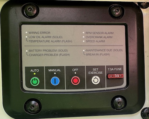
- Verify that the PowerPact has a compatible controller - the panel should resemble this:
- Gain access to the battery compartment inside the generator by removing the two screws holding the metal partition in place.
- Verify that there is an 8-pin Molex Minifit Jr connector on the underside of the controller (referred to as the accessory port) where the cable from the MobileLink plugs in. This will ensure the rest of the procedure has a good chance of success.
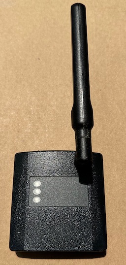
- If you have not already done so, obtain a Raspberry Pi. Recently (mid-2023), availability of Pis has been improving. You can track availability here. You should also obtain a Hat interface module from the PintSize.Me store. Install the Genmon software according to the setup instructions in the wiki and test the setup before connecting to the generator, including the serial loopback test. This example uses a Pi Zero W (built-in Wifi) and the PintSize.Me pHat:
- Press the off button on the control panel, remove the fuse on the controller front panel, turn off the circuit breaker, and disconnect the wires to the positive battery terminal.
- Remove the old MobileLink module and disconnect its 6-pin connector.
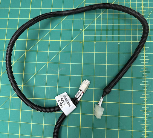
Here is the old cable, showing the 8-pin controller connector (only two pins are used) and the 6-pin MobileLink connector. Note that the old cable has wire labels which are referenced in the diagrams below. Your version may be different. Not shown is the end going to the battery:
- Make sure you understand the existing wiring for the MobileLink before proceeding - you will be reusing the existing cable. If you want to make your own cable from scratch see Making a Cable in the project wiki.
- For reference, here is the pinout for the PintSize.Me Molex connector:

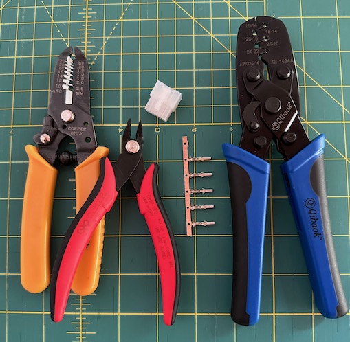
- You are going to be cutting the wires going into the 6-pin Molex connector that was plugged into the MobileLink. You will need several items: wire cutters, wire strippers, a Molex-compatible crimping tool, a set of Molex Minifit Jr female pins (at least 5), and a Molex Minifit Jr male shell. A kit of Molex parts is available here, or you can get them from sources like Mouser or Digikey.
- You will be re-pinning the wires from the old 6-pin connector and inserting them into the new 8-pin connector as follows:

-
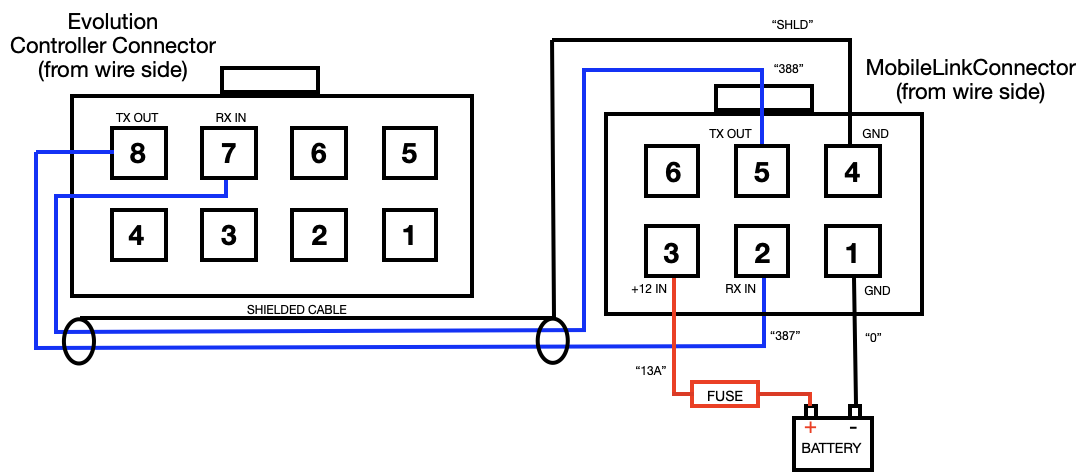
Note that as in other Genmon installations, the TX OUT from the controller goes to the RX IN on the Genmon, and the TX OUT from the Genmon goes to the RX IN on the controller. This is the "null modem" wiring used for RS232 connections.
-
Here is an example of how to crimp on new pins, one at a time, and insert them into the new shell:

- Once the new connector is wired in, verify the connections one more time for correctness. Plug in the Pi/Hat combo, ensuring it does not touch any metal, reconnect the battery + terminal, turn on the circuit breaker, and reinstall the panel fuse. The LED on the Pi should light up and the Pi should boot. Verify that the software is running with a browser. If you have connected the serial signals correctly, you should see data coming from the controller, such as battery voltage and utility voltage. After letting it run for a while, check the monitor tab in the web UI and verify that you are not seeing CRC errors in the Communication Stats section.
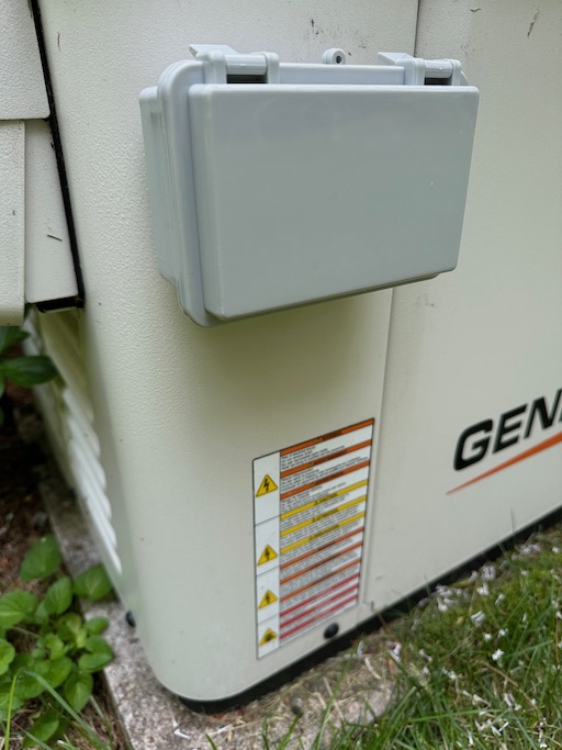
- If you are using a Pi Zero W, it is recommended that it is installed outside of the generator enclosure due to its limited antenna range. Here is an example of a watertight enclosure mounted on the outside using the same mounting hole as the old MobileLink. This uses the old conduit fitting supplied with the MobileLink, along with a 1" nut on the inside of the case, along with rubber washers between the enclosure and the generator. This example case was obtained here.
-
There are several examples of alternative mounting schemes and external antennas (using wifi dongles) on the issues page of the project GitHub.
-
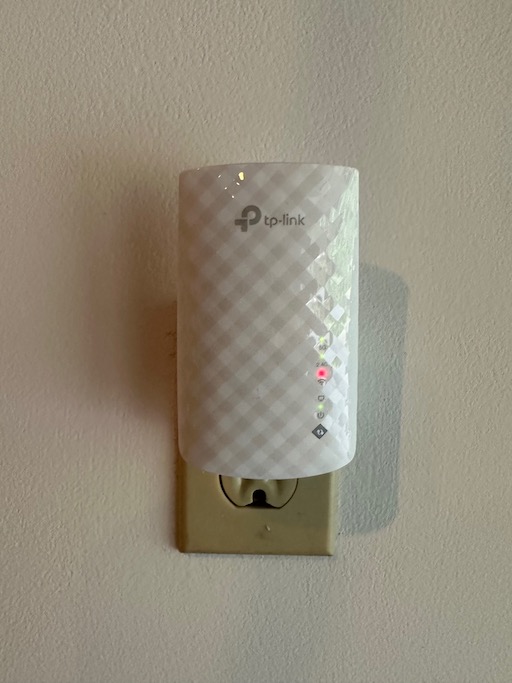
If you need to boost the wifi signal due to the distance to your router, this tp-link repeater is one example that has been used successfully: