This python (python 3.10) application provides a graphical interface to interact (GUI) with a BigFin Dcs5 XT or MICRO measuring board via Bluetooth. The application turns stylus inputs on the measuring board into keyboard entry, essentially turning the dcs5 measuring board into a wireless keyboard. A Marel Marine Scale can also be connected to the application. See the project marel_marine_scale_controller for more information and how to set up the scale.
Downloading the Dcs5 Controller App from the latest release.
- Download
dcs5.zipfrom the last version here. - Unzip
dcs5.zip - Run
dcs5\dcs5.exe
The application will generate a local files upon its initial launch at:
- Windows:
%localappdata%\dcs5\ - Linux:
~/.dcs5/
Where it will also save the different configurations and log files.
The following v2-0-0-iml firmware needs to be installed on the measuring board in order to use this application.
Contact Big Fin Scientific to learn how to update your measuring boards firmware.
- python 3.10
Guide d'utilisation en français pour le modèle XT : user_guide_fr.
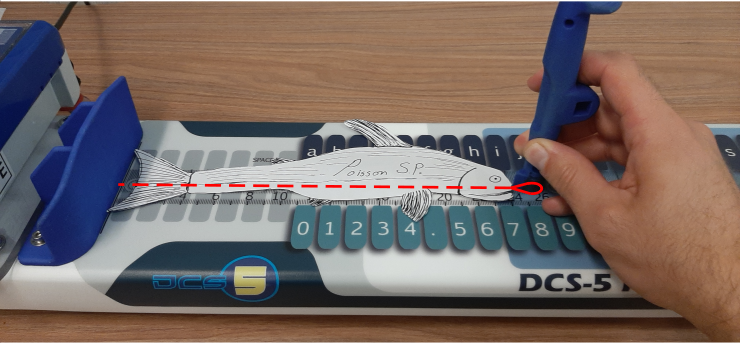
The stylus needs to be placed within the detection zone. The detection delay can be adjusted in the configuration (See section Configuration files). The control box lights will flash when a measurement is made.
Board Detection ZoneThe measurement board has 3 different output modes; length, top and bottom. The top and bottom mode are used to access the top and bottom keys by placing the stylus on the corresponding circle within the detection zone of the board. There are 2 ways to change the output mode: by mapping commands to the control box keys or by defining swiping regions on the board.
Commands can be mapped to change to a specific output mode or to cycle through the output modes.
- See section Configuration files for the output mode commands.
Furthermore, the default LED display of the control box changes depending on the output modes.
- See section LEDs Displays.
Swiping from left to right in a swiping zone will change the output mode.
The swiping regions are defined in the configuration files.
For example, here are the defaults swiping regions for the xt control box.
The corresponding output modes are:
- Left, Right : Length
- Blue : Top
- Green: Bottom
The map definition in the configuration file is:
  {"output_modes": {
      "segments_limits": [0, 230, 430, 630, 800],
      "segments_mode": ["length", "top", "bottom", "length"]
}}- See section Device Specification for information on how to define the swiping region.
Measurements are made by placing the stylus head flat on the board within the detection zone. You can change the measurement/detection settings in the controller_configuration.
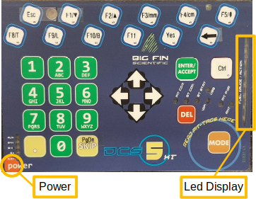
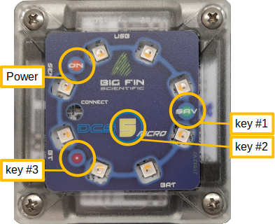
The only difference between the xt and micro control box models are the number of keys and the LED display and flash sequence.
- 32 keys
- 3 keys
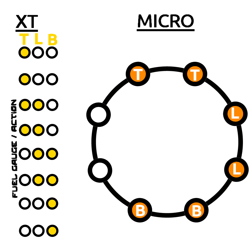
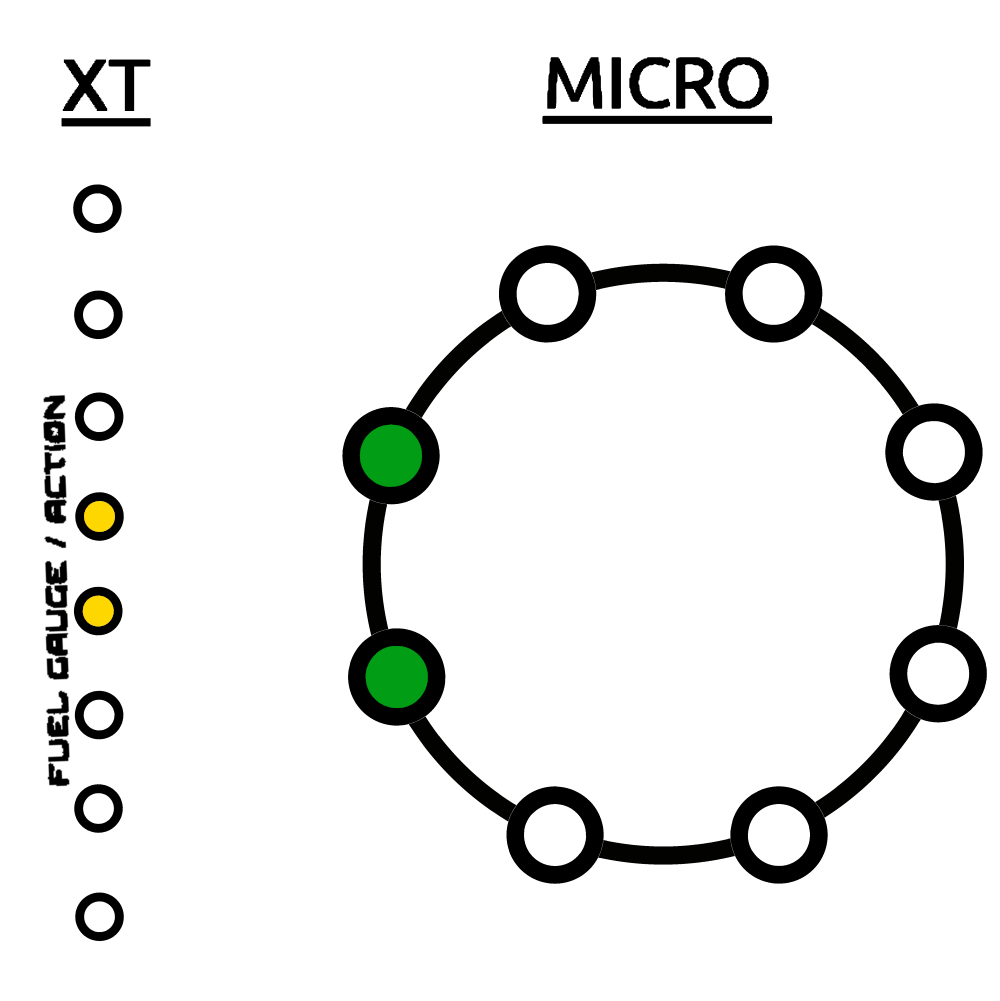
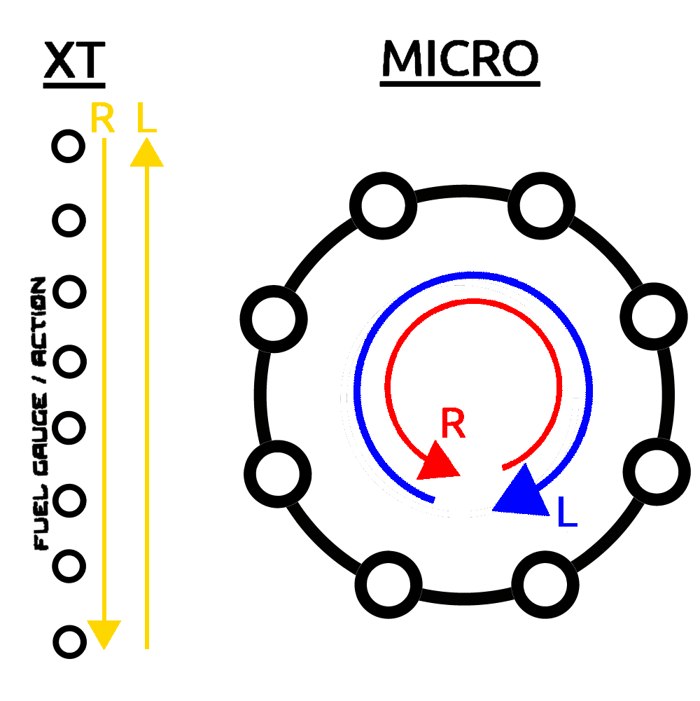
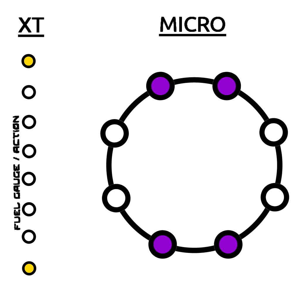
Different LEDs patterns are displayed on the control box to give feedback to the users.
- xt:
FUEL GAUGE / ACTIONLED bar - micro: LED Ring
The default pattern displays the current output mode.
Output Mode LED Display- T: Top
- L: Length
- B: Bottom
The follow led pattern is displayed when the board detects the stylus.
Stylus Detection LED DisplayAll the leds flash rapidly when a measurement is made.
Measurement LED Display Swipe LED Display- L: Right to Left swipe
- R: Left to Right swipe
In calibration mode, the default display changes to
Calibration Mode LED DisplayThen, once the stylus is placed down, the leds will slowly light up in the following sequences. When the point is successfully calibrated is over, all the leds will rapidly flash.
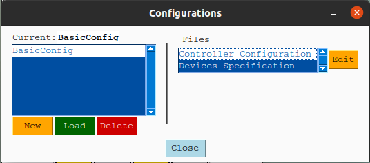
Calibration LED DisplayThe application requires a configuration to work. To load and manage configuration, click on Dcs5 > Configuration in the top bar.
Application Menu WidgetFrom the Configuration window, you can create New, Load, Delete and Edit configurations.
Config WindowDefault configurations are provided for the xt and micro models.
Select the Control Box model (xt or micro) and enter a name for the new configuration.
The bluetooth address of the controller (mac address) will need to be changed once a new configuration is created.
Select the configuration and the Controller Configuration file and press Edit.
In the json file, change the following value:
client -> mac_address
See section Configuration files for more information on the different configuration parameters.
To connect to the Dcs5 measuring board, the Board Mac (bluetooth) address needs to be specified in the Controller Configuration file. You can edit the file via the configuration menu (see sections Configurations and Controller Configuration)
Then connect the board by pressing the Connect button.
Connect WidgetThe red circle next to the Connect button will turn into a yellow triangle while the application is attempting to connect to the board and then into a green when connected. When connecting the board, the application will synchronize with the board control box. (See the section Additional GUI features). The application and the board are synchronized when the application receives confirmations that the board internal parameters (mainly those related to stylus detection) are the same as those specified in the configuration files. If the synchronization failed, indicated by a red circle next to the Synchronize button, you can press the Synchronize button to try again. If it still doesn't work, try to restart the board and the application.
The board needs to be calibrated using two calibration points.
Although the calibration is linear, keep in mind that the stylus has some non-uniform thickness which will offset,
to some extent, the measured values if the stylus's orientation differs when measuring versus when calibrating.
We recommend using the tiniest part of the stylus to make the calibration
and then add offset in the calibration files for each stylus.
- See section Device Specification.
To calibrate the board, click on Set Cal. Pts.
Calibration WidgetIn the calibration points window set the two calibration points in mm.
Calibration Set. Cal. Pts. WindowPress the Calibrate button to enter the calibration mode, from there follow the instruction given by the application. Note that a right to left swipe will exit the calibration mode. For each calibration point, the calibration progress will be shown by the following LEDs display once the stylus is placed down. If the stylus is lifted or moved too much before the calibration is done, the calibration restart.
Application Window Application Marel WidgetConfigurations are created and modified via the application GUI (See section configuration). A configuration is made of two json files that are used to change the controller and measuring board behavior.
Default xt file: xt_controller_configuration.json
Default micro file: micro_controller_configuration.json
Usage:
-
client: (Connection parameters)
{"client": { "device_name": "BigFinDCS5-E5FE", "mac_address": "00:06:66:89:E5:FE", "marel_ip_address": "192.168.0.202" }}- device_name: Name of the device. (Only used to display in the app.)
- mac_address: Bluetooth (mac) address of the measuring board i.e. 00:06:66:89:E5:FE.
- marel_ip_address: Ip address of the Marel Scale (see marel_marine_scale_controller).
-
launch_settings: (Settings used when the app is launched)
{"launch_settings": { "output_mode": "length", "reading_profile": "measure", "dynamic_stylus_mode": true, "backlighting_level": 95, "length_units": "mm", "stylus": "pen", "auto_enter": true }}- output_mode: top, length or bottom.
- reading_profile: Name (key) of the profile. The reading profiles are defined below.
- dynamic_stylus_mode: (true/false) If true, reading profiles will change for each output mode as defined in the next section.
- backlight_level: (0-95) Backlight intensity
- length_units: Units of the measurements values either cm or mm
- stylus: Name of the stylus in use. Must be defined in the devices_specifications configuration file.
- auto_enter: Automatically press the enter key after a length or weight value is printed.
-
reading_profiles:
{"reading_profiles": { "measure": { "settling_delay": 9, "number_of_reading": 50, "max_deviation": 50 }}}- settling_delay: (0-20) Delays after the stylus is first detected. (not seconds)
- number_of_reading: Number of readings needed for a good measurements.
- max_deviation: (1-100) Amount of deviation allowed between each reading. Notes: For more information : Big-Fin-Scientific-Fish-Board-Integration-Guide-V2_0.pdf
-
output_modes:
{"output_modes": { "swipe_threshold": 5, "segments_limits": [0, 230, 430, 630, 800], "segments_mode": ["length", "top", "bottom", "length"], "mode_reading_profiles": { "top": "key", "length": "measure", "bottom": "key" } }}- swipe_threshold: Minimal distance (mm) for a stylus swipe to be valid.
- segments_limits: Define the boundaries (mm) of the different swipe segments.
- segments_mode: The corresponding output_mode for each swipe segment.
- mode_reading_profiles: The corresponding reading_profiles for each output mode.
-
keys_maps (See Key Mapping section):
Fields:
control_box,control_box_mode,board,board_mode- A key can be mapped to commands or keyboard inputs.
- A map can be a list of commands or keyboard inputs which are executed one at a time.
- A key can have two mappings: One default and when the alternative (mode) mapping.
The names of the keys are set in devices_specification configuration file.
Mappable commands :
"BACKLIGHT_UP", "BACKLIGHT_DOWN": Change the control box backlight level."CHANGE_STYLUS": Cycle through the list of stylus defined in the devices_specifications configuration file."UNITS_mm", "UNITS_cm": Change output units."MODE_TOP", "MODE_LENGTH", "MODE_BOTTOM": Change the output mode."CHANGE_OUTPUT_MODE": Cycle through output mode (TOP, LENGTH, BOTTOM)."MODE": Access the alternative (mode) mapping (control_box_mode,board_mode)."WEIGHT": Prints the weight measured by the Marel Scale (if one is connected)."DELETE_LAST: Delete the last printed value."PRINT <string to print>": Prints the<string to print>value. e.g. "PRINT This Will be Printed"
Valid keyboard input (Source: PyAutoGui):
['\t', '\n', '\r', ' ', '!', '"', '#', '$', '%', '&', "'",
'(', ')', '*', '+', ',', '-', '.', '/', '{', '|', '}', '~',
':', ';', '<', '=', '>', '?', '@', '[', '\\', ']', '^', '_', '`',
'0', '1', '2', '3', '4', '5', '6', '7', '8', '9',
'a', 'b', 'c', 'd', 'e', 'f', 'g', 'h', 'i', 'j', 'k', 'l', 'm', 'n', 'o',
'p', 'q', 'r', 's', 't', 'u', 'v', 'w', 'x', 'y', 'z',
'A', 'B', 'C', 'D', 'E', 'F', 'G', 'H', 'I', 'J', 'K', 'L', 'M', 'N', 'O',
'P', 'Q', 'R', 'S', 'T', 'U', 'V', 'W', 'X', 'Y', 'Z'
'accept', 'add', 'alt', 'altleft', 'altright', 'apps', 'backspace',
'browserback', 'browserfavorites', 'browserforward', 'browserhome',
'browserrefresh', 'browsersearch', 'browserstop', 'capslock', 'clear',
'convert', 'ctrl', 'ctrlleft', 'ctrlright', 'decimal', 'del', 'delete',
'divide', 'down', 'end', 'enter', 'esc', 'escape', 'execute', 'f1', 'f10',
'f11', 'f12', 'f13', 'f14', 'f15', 'f16', 'f17', 'f18', 'f19', 'f2', 'f20',
'f21', 'f22', 'f23', 'f24', 'f3', 'f4', 'f5', 'f6', 'f7', 'f8', 'f9',
'final', 'fn', 'hanguel', 'hangul', 'hanja', 'help', 'home', 'insert', 'junja',
'kana', 'kanji', 'launchapp1', 'launchapp2', 'launchmail',
'launchmediaselect', 'left', 'modechange', 'multiply', 'nexttrack',
'nonconvert', 'num0', 'num1', 'num2', 'num3', 'num4', 'num5', 'num6',
'num7', 'num8', 'num9', 'numlock', 'pagedown', 'pageup', 'pause', 'pgdn',
'pgup', 'playpause', 'prevtrack', 'print', 'printscreen', 'prntscrn',
'prtsc', 'prtscr', 'return', 'right', 'scrolllock', 'select', 'separator',
'shift', 'shiftleft', 'shiftright', 'sleep', 'space', 'stop', 'subtract', 'tab',
'up', 'volumedown', 'volumemute', 'volumeup', 'win', 'winleft', 'winright', 'yen',
'command', 'option', 'optionleft', 'optionright']-
Default
xtfile: xt_devices_specification.json -
Default
microfile: micro_devices_specification.json
Usage:
-
board:
{"board": { "number_of_keys": 49, "key_to_mm_ratio": 15.385, "zero": -3.695, "detection_range": 2} }- number_of_keys: The keys correspond to the grey circle on the board.
- key_to_mm_ratio: The distance in mm entre deux cercles (center to center).
- zero: The position (in mm) of the left edge of the key #0 given that the first key on the board is key #1.
- detection_range: Offset to the left in mm for stylus detection.
- keys_layout: Ordered lists for the name of the top keys and the for the bottom keys. These names are used to map command.
- Top:
- Bottom:
Notes: The two lists (top and bottom) should not contain identical names.
-
control_box:
- model: Model of the control box. Either xt or micro.
- keys_layout: Mapping of the controller box key builtin id to meaningful name. These names are used to map command in controller_configuration file.
-
stylus_offset: Offset in mm that is added to the value measured by the board.
- Note: These values will depend on the calibration.


