Making your own printer with an Arduino
There are plenty of ways of putting one together with various different Arduinos, but this guide will use the simplest configuration. If you have more Arduino experience, feel free to adapt this to your own components.
We've prepared a reasonably detailed list of components, but generally here's what you need:
- Printer (including paper and connecting wires) (available from adafruit, sparkfun, proto-pic, cool components...)
- Arduino Uno R3
- Arduino ethernet shield (including MicroSD card slot)
- A small breadboard
- MicroSD card (FAT formatted; any size will do)
- Three LEDS
- Four 560 ohm resistors (green-blue-brown-gold)
- A push-button switch
- A bunch of breadboard and jumper wires -- I've used jumper wires to keep the breadboard tidy, but you can use normal breadboard wires for everything if you like
- One three-pin header, and one two-pin header -- I've used angled ones, but you don't need to, and you can also substitute normal breadboard wires too
- 5V power adaptor (not pictured; also, the more current it can supply the better. I've been using 1.5-2.5amp power supplies)
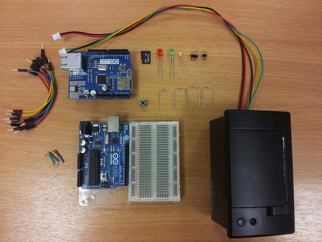
You can probably substitute a bunch of this stuff if you don't have quite the right resistors, LEDs or wires.
First, make sure your MicroSD card is FAT formatted and has at least 150k of spare space on it. I'm showing a 2GB card here but really the best thing would be to find a small capacity one and wipe it clean.
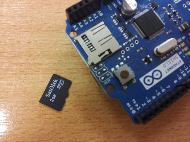
Insert the card into the ethernet shield, until it clicks in.

Then mount the ethernet shield on top of the main Arduino board, making sure that all the pins are nicely seated. I had to slightly coax some of the pins on my shield when I first received it -- as always, be patient and eventually it will happily slot into place.

You'll need to load the printer software (the 'sketch' in Arduino parlance) onto the Arduino.
You can find the sketch here
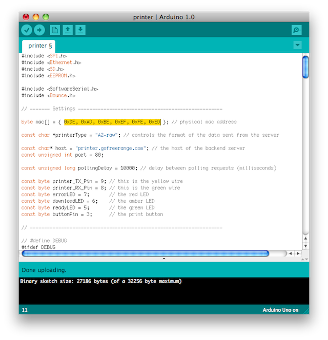
You should change the MAC address near the top of the sketch, but otherwise you shouldn't need to change anything else (although, of course, you can).
You may also need to install the the Bounce arduino library, which makes the button more reliable. This should be placed in your Arduino libraries directory, and you may need to restart the Arduino IDE before it recognises that it is available.
Once you're ready, use the Arduino software to upload the sketch to your Arduino, then disconnect it from the computer.
Next, go to your breadboard. We're going to wire up the button first. This is the button that you'll press when there's some data ready to be printed.
Put it at the end of the breadboard, and make sure it's firmly seated.
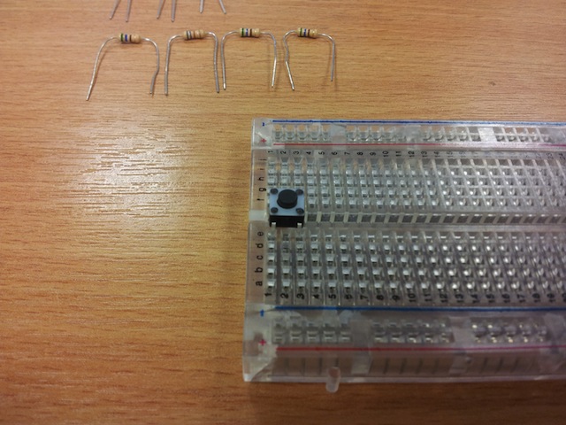
We need to deal with three of the four pins on the button. Firstly, we're going to wire the one nearest us and the edge of the board to the positive voltage rail of the breadboard.

As I mentioned above, I've used a jumper wire to keep this (relatively) neat, but you can make the connection directly with a breadboard wire should you wish.
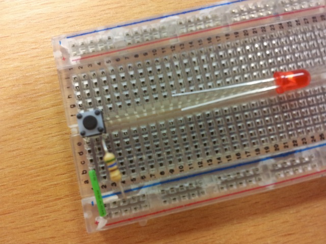
Next, we wire up the other button pin on our side to the ground rail of the breadboard, via one of the 560 ohm resistors.

We'll deal with the third pin of the button when it's time to wire up the board to the Arduino.
Now, lets get the LEDs ready. I've used three LEDs for each of the available signals that the Arduino is going to provide (ready, downloading, and error). You can, of course, use whatever colours you like. Technically you only need the ready LED (green in this guide), so you can tell when a printout is pending.
We're going to connect the LED cathode (-, the shorter leg, and normally the side of the LED with a flattened edge) to the side of the breadboard that's closest to us, so the anode (+, the longer leg) is closer to the voltage and ground rails we'll be using.
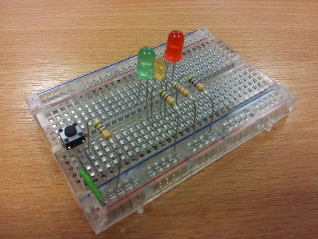
You can connect all three LEDs in this way. I've spaced the LEDs out slightly here.

Next we need to connect each of the LED cathodes to the ground rail via a 560 ohm resistor.
In order to make some of the wiring simpler we're going to use both sets of ground and power rails on the breadboard. Wire them together like so.
/images/11_connect_ground_and_live_rails.JPG
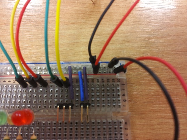
With the button and LED in place, we can move onto the connection for the printer itself. The data cable requires three pins (transmit, receive and ground), while the power cable only requires two.
I've used angled headers, but you can use straight headers, or just use breadboard wires directly if you like.

We need to wire the ground pin from the data header to our ground rail, and the positive and ground pins for the power header to the corresponding rails.

All the major components are in place, and your board should look a bit like this now.

We can now start adding the wires that will connect our circuit to the Arduino. Firstly, the wire for the button should be connected to the pin on the opposite side of the button from the resistor.

Each of the LEDs needs a wire connected to the anode.
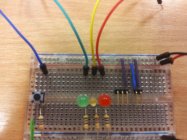
Finally, the printer data connection needs two wires. The printer cable uses green, yellow and black; I've kept those colours consistent, so the green breadboard wire should be leftmost, and the yellow wire in the middle.

Finally we add two wires to the power rail, for bringing power from the Arduino to the breadboard.
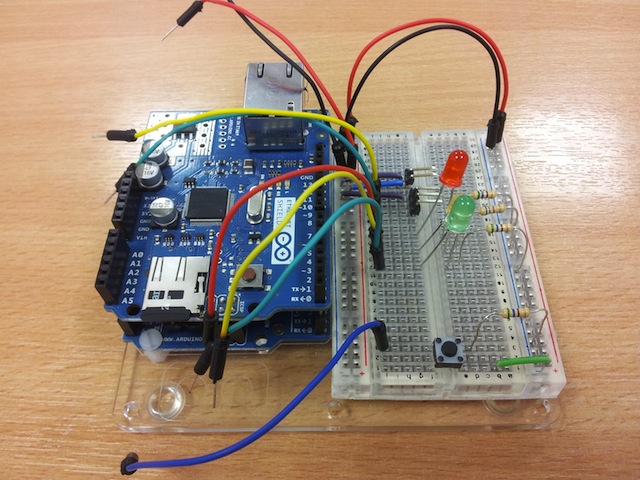
This is what your finished board should look like.


Lets start connecting up to the Arduino.
If you haven't edited the sketch, the button wire should be connected to digital pin 3 of the Arduino.
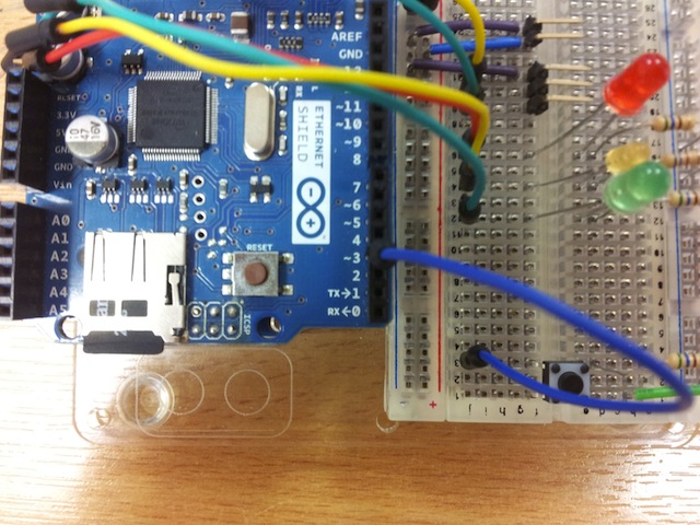
Pin 4 of the ethernet shield is in use by the MicroSD card, so the LED wires should be connected to digital pins 5, 6 and 7.

The printer wires should be connected to digital pins 8 (green) and 9 (yellow).

Last but not least, connect the power wires to the Vin and ground pins on the far side of the Arduino.

Now we're ready to connect the printer to the board. Firstly connect the power and data cables into the back of the printer

And then connect the cables to the headers (or wires) on the board. Make sure to get them the right way round!

Finally, plug in an ethernet cable which is connected to your network, plug in the power, and after a few seconds while everything initialises, you should be ready to go! Make sure you plug in the power supply; your USB connect does not have enough current for the thermal printer component.

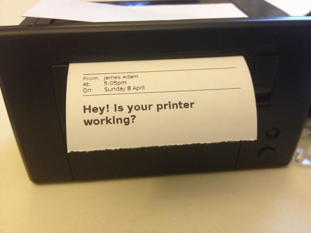
What you should see when it's running is the centre (yellow in this case) LED blinking every 10 seconds. If the printer cannot connect to the server, the red LED will flash five times. When some data is ready to be printed, the yellow LED will light as it is downloading, and then the green LED will stay on until the button is pressed.
Hopefully your printer is now happily connected to the backend server. Let's get printing things!
The first thing to do is determine your printer URL. Visit the backend server at http:https://printer.exciting.io/my-printer and you should see the information about your printer.

We're going to set you up with the "printer mail" demonstration app, and for that we need your print URL. Right click and copy it to your clipboard.
Next, visit the printer mail app at http:https://printer-mail.herokuapp.com.

Register your printer with a nickname, and paste the print URL below it. You can choose any nickname you like, although it's probably best to choose a short word without any phrases or punctuation (it's only a demo app and so it's not hugely robust!).

Once your printer is registered, you (or other people) can send messages to it by visiting the URL like http:https://printer-mail.herokuapp.com/send/exciting.

Fill in whatever text you like; this is just a test after all. Then click send.
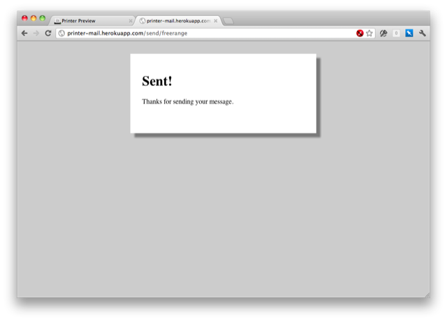
After a few seconds (once the backend has finished processing the message), you should see the printer download the message and the green LED turn on.
(Alas github wikis don't let me embed that video.)