UETRV_Pcore is a RISC-V based application class SoC integrating a 5-stage pipelined processor with memory and peripherals. Currently, the core implements RV32IMACZicsr ISA based on User-level ISA Version 2.0 and Privileged Architecture Version 1.11 supporting M/S/U modes. Following are the key features of the SoC:
- 32-bit RISC-V ISA core that supports base integer (I) and multiplication and division (M), atomic (A), compressed (C) and Zicsr (Z) extensions (RV32IMACZicsr).
- Supports user, supervisor and machine mode privilege levels.
- Support for instruction / data (writeback) caches.
- Sv32 based MMU support and is capable of running Linux.
- 32 KB 4-way set associative instruction cache.
- 32-KB direct mapped write-back data cache.
- Cache size, TLB entries etc., are configurable.
- Intergated PLIC, CLINT, uart, spi peripherals.
- Uses RISOF framework to run architecture compatibility tests.
- Coremark: 2.0 Coremark/MHz with DDR2 based main memory.
- LUTs for core (including MMU) < 4.5k and for the SoC (including cache controllers but excluding DDR controller) < 6k.
The UETRV_Pcore is an applicaion class processor capable of running Linux. A simplified 5-stage pipelined block diagram is shown below. The M-extension is implemented as a coprocessor while memory-management-unit (MMU) module is shared by instruction and data memory (alternatively called load-store-unit (LSU)) interfaces of the pipeline. Specifically, the page-table-walker (PTW) of the MMU is shared and there are separate TLBs (translation look aside buffers) for instruction and data memory interfaces. The A-extension is implemented as part of the LSU module.
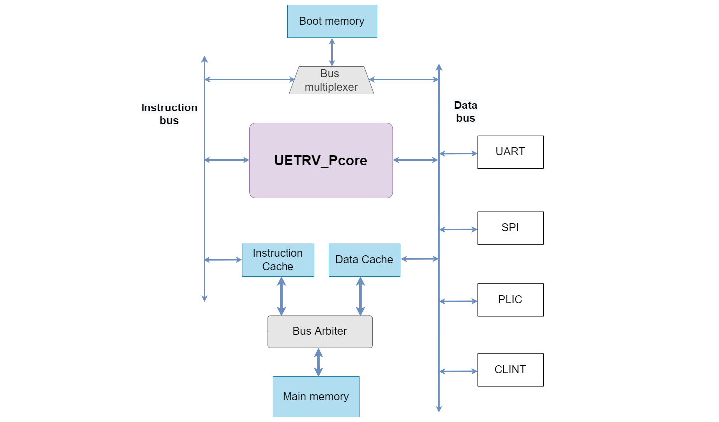
The SoC block diagram shows the connectivity of the core with memory sub-system as well as different peripherals using data bus. The boot memory is connected to both instruction and data buses of the core using a bus multiplexer. The instruction and data caches share the main memory using a bus arbiter. Different necessary peripherals are connected using the data bus. Further details related to the SoC design are available at https://uetrv-pcore-doc.readthedocs.io/en/main/.
The memory map for the SOC is provided in the following table.
| Base Address | Description | Attributes |
|---|---|---|
| 0x8000_0000 | Memory | R-X-W |
| 0x9000_0000 | UART | R-W |
| 0x9400_0000 | PLIC | R-W |
| 0x9C00_0000 | SPI | R-W |
| 0x0200_0000 | CLINT | R-W |
| 0x0000_1000 | Boot Memory | R-X |
R: Read accessW: Write accessX: Execute access
Install RISC-V toolchain and verilator. These tools can be built by following the instructions in the corresponding links, or can be installed directly by running the following command
sudo apt-get install -y gcc-riscv64-unknown-elf verilator gtkwave
Check that these tools are installed correctly, by running verilator --version and riscv64-unknown-elf-gcc -v.
Verilator model of Pcore can be built using Makefile:
make verilate
The verilator model is build under ver_work/Vpcore_sim. The executeable can accept the following three parameters:
imem: This paramerter accepts the file that contain the hexadecimal instructions of compiled program.max_cycles: This parameter cotrols the maxiumum number of cycles for simulation. Simulation terminates after executing these many cycles.vcd: This parameters accepts a boolean value. If it is 0, the waveform filetrace.vcdwill not be dumped and vice versa.
An example program to print HELLO on terminal via UART is compiled and its hex instructions are availabe in here. Run the following command to simulate the example program
make sim-verilate-uart
This will simulate hello.hex and dump UART logs in uart_logdata.log file. If vcd=1 is added to the above command, trace.vcd will be created that can be viewed by running
gtkwave trace.vcd
The imem and max_cycles may be overwritten in Makefile using.
make sim-verilate-uart imem=</path/to/hex/file> max_cycles=<No. of cycles>
UETRV_Pcore uses RISOF framework to run Architecture Compatibility Tests (ACTs). Instructions to run these tests can be followed in verif directory.
Using the same procedure as outlined above, we can simulate the Linux bootup using a prebuilt image (imem.zip) available in ./sdk/example-linux/ folder. The pre-built Linux image is prepared using initramfs based root file system (rootfs) and is directly linked into the kernel. Furthermore, the Linux/kernel image is linked as a payload to the OpenSBI that acts as a first-level bootloader. The imem.zip image contains:
- Root file system (
rootfs.cpio) based oninitramfsusing Busybox 1.33 - The Linux (version 6.1.0) with rootfs.cpio linked into the kernel
- OpenSBI (ver. 0.9) based first order bootloader with Linux kernel as payload
During booting process, the processor starts executing zero-level bootloader from bmem and then jumps to first-level bootloader (OpenSBI), which after necessary initializations, hands the control over to the kernel.
For Verilator based simulation one configurtion is required. Open the file rtl/defines/pcore_config_defs.svh and uncomment the line ` define RTL_SIMULATION 1. Now run the following command to extract the imem.txt to ./sdk/example-linux/ and simulate the Linux booting process using this pre-built image.
make sim-verilate-linux
The output is logged to the uart_logdata.log file (a copy of this log is available in ./sdk/).
The processor is tested using Nexys-A7 (100T) FPGA board and Vivado 2019. Type in the following command to open the project in Vivado 2019
vivado PCore_FPGA/PCore_FPGA.xpr
Make sure that ` define RTL_SIMULATION 1 is commented out, while ` define DRAM 1 is uncommented in the file rtl/defines/pcore_config_defs.svh. The instruction and data cache sizes can also be configured here.
New bitstream can be generated with the exisitng project or you may use the prebuilt bitstream available in the folder FPGA_Target/Bit_stream
- Load the bitstream on the FPGA, your serial monitor will show message
Load File - Type in the following commands to load the prebuilt Linux image
cd sdk/load_image python3 serial_sendfile.py <baud_rate in MHz> <path/to/image/file> - Baud rate of existing bitstream is
4000000. Sample Linux image is saved insdk/load_imagefolder. - If using default baud rate and default bitstream, the following command can be run
python3 serial_sendfile.py 4 imem.bin
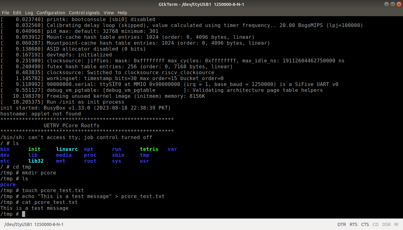
After successful downloading of the image the booting process starts. A snapshot of the boot log is shown below.


