This is a photoacoustic NDIR CO2 sensor node, utilizing energy harvesting from PV cells to allow for batteryless operation.1
The sensor communicates with the backend/database through 6LoWPAN on a Thread network.
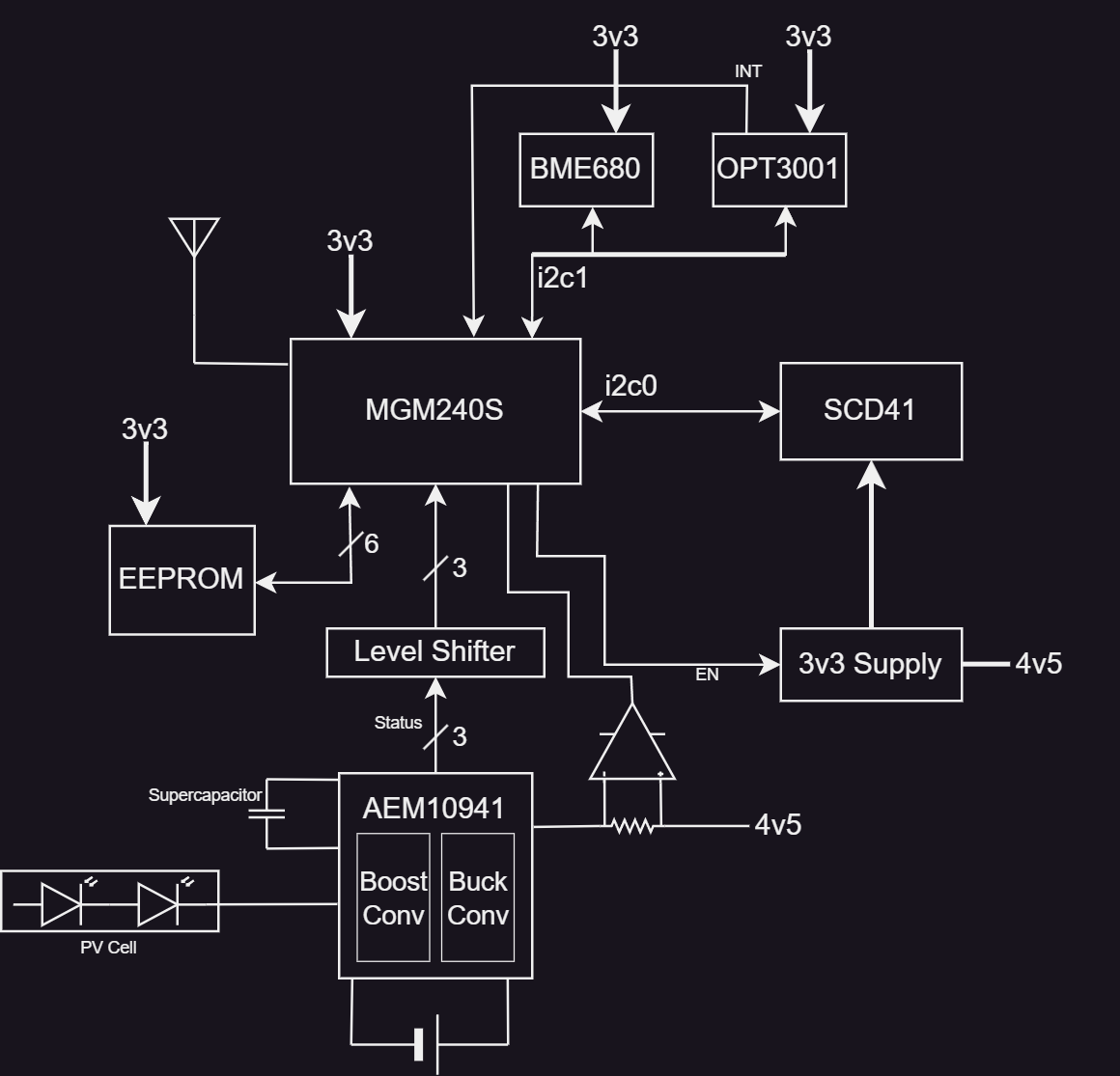
Refer to the functional block diagram below for an overview of the circuit design.

Figure 1: CO2SN Functional Block Diagram
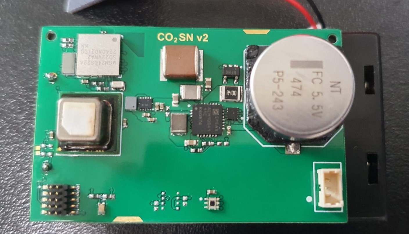
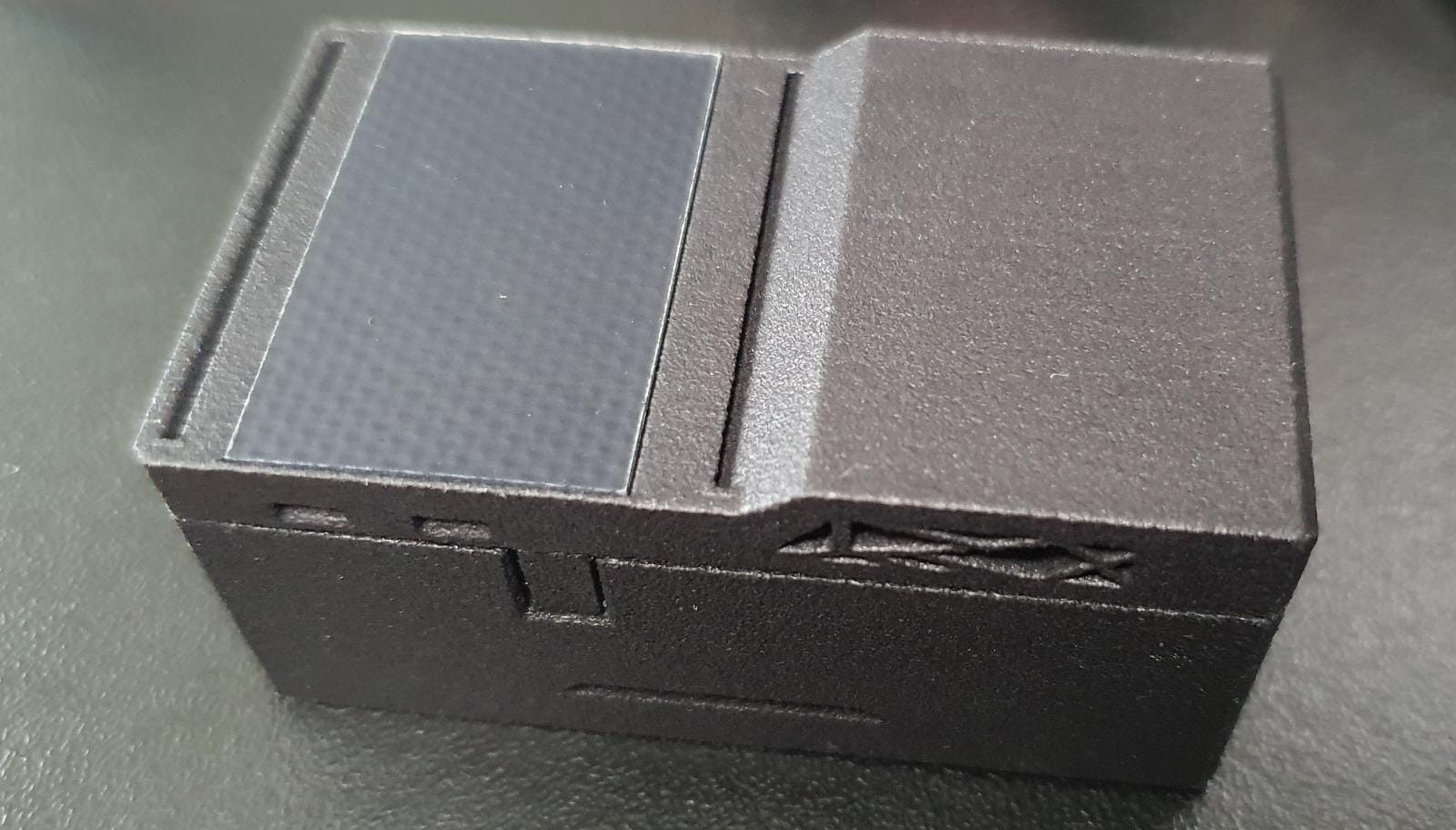
The figures below depict the custom PCB and enclosure.
Figure 2a: CO2SN PCB(left), Figure 2b: CO2SN Enclosure (right)
In general, there are 3 power sources used: the PV cell array (SM141K05TF), supercapacitor (FC0H474ZF), and 2xAA (optional) backup.
The primary assumption is that this sensor will receive only indirect sunlight and/or artificial lighting, hence a larger capacity from other storage technologies such as LIC/Li-ion may not be preferable if the capacity cannot be properly utilized, hence the use of a supercapacitor for the expected multiple discharges (including partial ones) per day. Furthermore, exposure to direct sunlight will introduce a non-trivial heating effect on the sensor elements; it is not known how the sensor readings would be affected.
In the daytime, indoor lighting (approx. 350lux) is largely sufficient to indefinitely sustain a 1.5h sampling rate.
For completely non-battery backed operation, assuming a fully-charged supercapacitor with
The sensor can also be configured to run completely off batteries.
The quiescent power consumption (IQ) breakdown by design for all non-trivial loads at TA=25 degC are as follows:
| Device | Current Consumption (Typ) | Conditions |
|---|---|---|
| ST1PS03 | 500nA | |
| MGM240S | 2.9µA | 256kB RAM on, LFXO |
| AEM10941 | 0.5µA | LDO off |
| OPT3001 | 0.4µA | FS Lux |
| SCD41 | 0.5µA | PD |
| MAX9634 | 1.1µA |
Initial designs where the sensors were segmented into seperate power domains and power gated did not yield good results, in some cases even increasing the total power due to cold start-up sequences.
The supercapacitor (FC0H474ZF) maintains a charge current of <2µA after the initial absorption current. This will be assumed to be the leakage current ILEAK for all Vcap > Vhold. The self-discharge characteristic is given by an exponential, then a linear decay [2].
Based on empirical data (measured at the VBACK node, the average current of the system can be estimated (with the use of the algorithm):
For a typical application, such as in a home, CO2 rates change logarithmically [1] provided some ventilation. Hence, sample rate could be adjusted based on the previous measurements' rate of change.
However, in most cases, a sample rate of 30mins-1h (<115µA) is sufficient to detect dangerous changes in indoor CO2 concentrations. With approx. 350 lux from an indoor LED source in the range 400-1000nm (where the QE exceeds 80%), batteryless operation is achievable.
This project utilizes a custom algorithm designed for ultra-low power applications such as this one, where the manufacturer supplied algorithm is unworkable.
The algorithm is designed to closely mirror the built-in algorithm.

Figure 3: Current profile (SCD41 measuring)
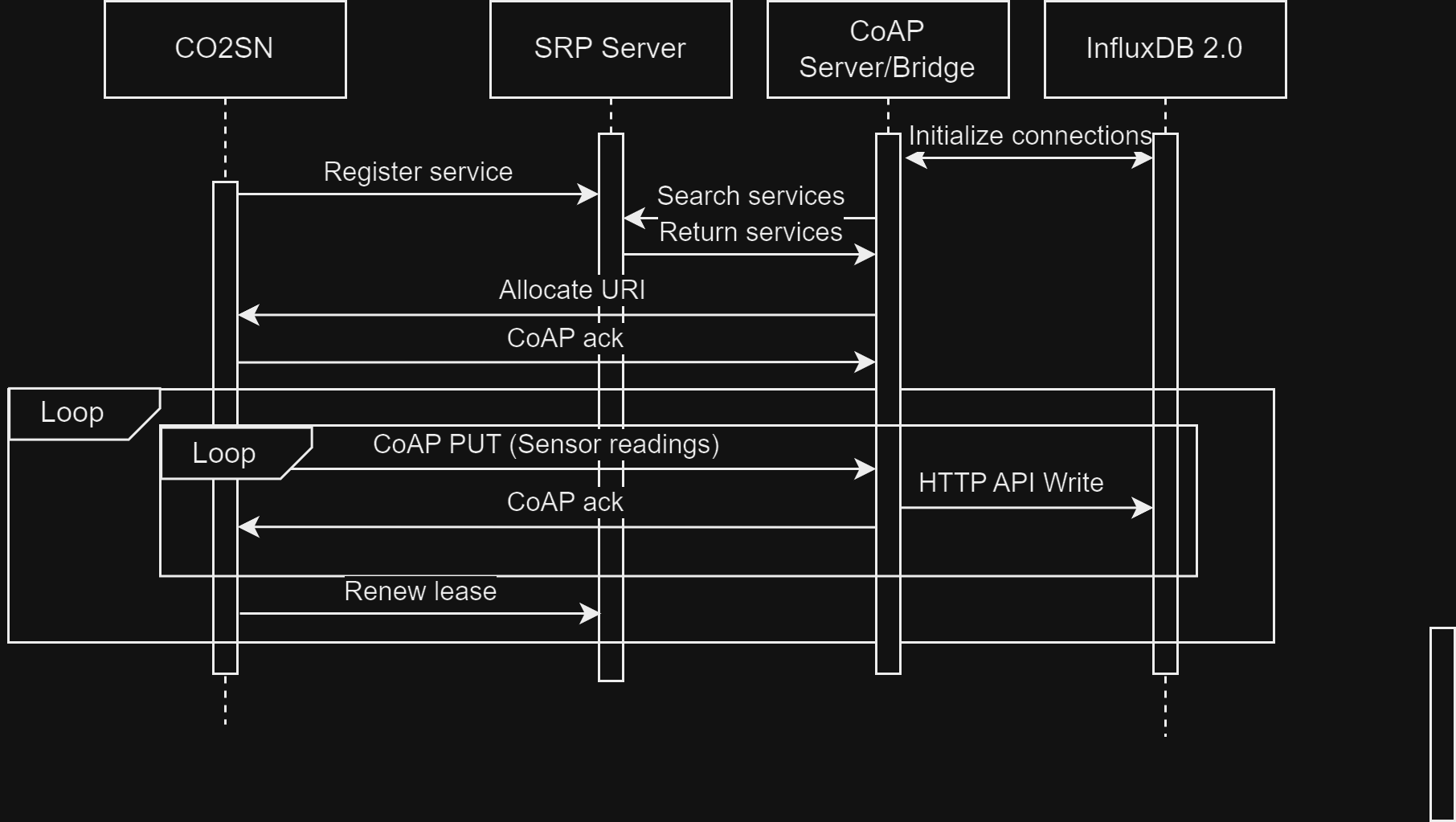
Figure 4 denotes the typical communication sequence that the device performs to send measurements to the InfluxDB database.

Figure 4: Communication Sequence Diagram
CoAP packets containing measurement data are sent aggressively (i.e. require ACK and repeated until received), while ordinary status or informational packets are fire-and-forget, in order not to waste a measurement.
[1]
Batog, P., & Badura, M. (2013). Dynamic of Changes in Carbon Dioxide Concentration in Bedrooms. Procedia Engineering, 57, 175–182. https://doi.org/10.1016/j.proeng.2013.04.025
[2]
Kowal, J., Avaroglu, E., Chamekh, F., Šenfelds, A., Thien, T., Wijaya, D., & Sauer, D. U. (2011). Detailed analysis of the self-discharge of supercapacitors. Journal of Power Sources, 196(1), 573-579.
Footnotes
-
This sensor is optionally battery backed by 2xAA cells, to allow for higher sampling frequencies and redundancy. ↩

